

Page 1
Owner’s Guide for
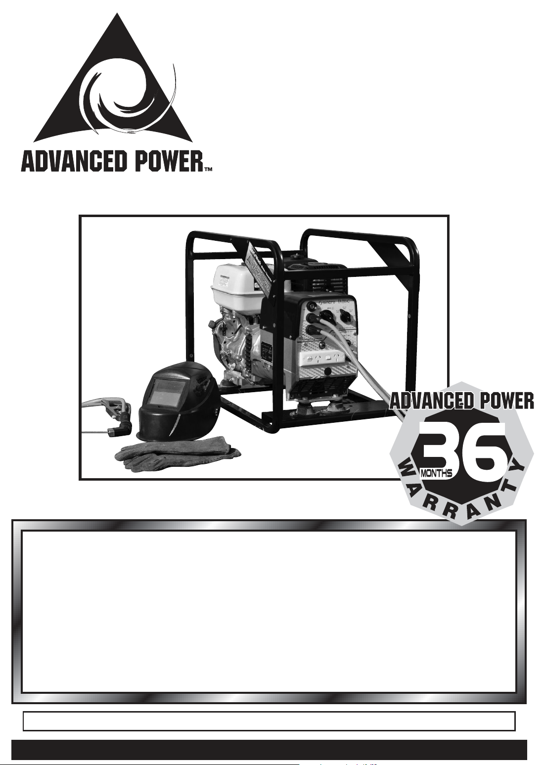
WELD ‘n’ WORK
Engine Driven
Welder Generators
*24 Months engine warranty on Vanguard powered sets
We are pleased to advise that your ADVANCED POWER Welding Set is covered by warranty for a
period of 36 months* from the date of its original purchase. Refer to the engine operation manual for
additional engine warranty details.
This warranty is subject to the terms and conditions of the respective manufacturers and covers
defects occurring under normal operating conditions caused by faulty materials or workmanship.
Excluded from this warranty are normal maintenance items, consumable parts and equipment
subjected to misuse, abuse, lack of maintenance or damage due to unauthorised servicing.
For warranty service, the equipment must be returned, freight pre-paid to an authorised
Advanced Power service agent.
Should you require warranty service or maintenance, please contact MPower on 1300 733 004
AWARD WINNERS FOR EXCELLENCE IN DESIGN OF GENERATORS
Page 2

Important Information
for all owners of
ADVANCED POWER
Engine Driven
Welding Sets
Thank you for purchasing an ADVANCED
POWER Welder Generator. We have
prepared this handbook to make it
easier and safer for you to use and care
for your Welder Generator. Please read
this handbook carefully as it contains
important information which may prevent
serious personal injury or equipment
damage.
Please read this leaet in conjunction
with the additional engine maintenance
information which can be found in the
accompanying engine owners manual.
Your ADVANCED POWER Welder
Generator has been run, tested and
tuned for optimum performance at the
factory prior to despatch. All petrol and
oil has been drained for safe transport
purposes.
DO NOT START YOUR WELDER-
GENERATOR until you correctly FILL
ENGINE CRANKCASE WITH OIL.
DO NOT ADJUST THE ENGINE SPEED.
HINTS FOR SAFE
OPERATION
AND BEST
PERFORMANCE
n FILL CRANKCASE WITH OIL
as recommended in the engine owner’s
manual. Check oil level daily.
DO NOT USE FRICTION MODIFIED OILS.
n USE ONLY FRESH QUALITY FUEL
in your Advanced Power Welder Generator.
DO NOT use fuel that has been stored for
several weeks.
n DO NOT ADJUST OPERATING SPEED.
This has been factory set. Alteration will vary
the output voltage and frequency, which will
cause damage to your appliances and/or
generator and void your warranty.
n ONLY ONE SECTION OF THE SET CAN
BE OPERATED AT ANY ONE TIME.
i.e. Welder or Alternator.
n DO NOT DISCONNECT THE LOW OIL
SENDER LEAD/WIRE. THIS WILL CAUSE
DAMAGE TO YOUR GENERATOR
WELDER AND VOID THE UNITS
WARRANTY
n DO NOT OPERATE YOUR PETROL/
DIESEL DRIVEN WELDER-GENERATOR
AT LESS THAN 1/3 FULL LOAD for long
periods. Light loading can cause glazing
of the cylinder bore , and cause increased
carbon build up in combustion chambers.
After long periods of operation at light
loads, the generator should be operated for
5 minutes at 75% load or more of its rated
capacity to disperse carbon build-up in the
combustion chamber.
ADVANCED POWER GENERATING SETS OWNER’S GUIDE2
Page 3

n When STARTING and STOPPING your
Welder Generator, TURN OFF ALL
CONNECTED APPLIANCES - ESPECIALLY
INDUCTION MOTOR DRIVEN APPLIANCES
such as refrigerators, water pumps, air
conditioners, workshop machinery and
electronic appliances such as TV sets.
Damage may occur to these appliances due to
the high/low voltage output from the generator
under starting and stopping situations.
n STOP ENGINE AND ALLOW TO COOL
BEFORE FILLING WITH PETROL OR
DIESEL. You may be seriously injured by re
or explosion if fuel is spilt and ignites.
n ALLOW ALL SPILT PETROL TO
EVAPORATE BEFORE STARTING OR
RE-STARTING THE SET.
n DO NOT SMOKE NEAR PETROL.
n DO NOT OPERATE YOUR WELDER
GENERATOR WITHOUT SUFFICIENT
VENTILATION.
Poisonous carbon monoxide gases colourless and odourless - are contained in
exhaust gases.
n NEVER CONNECT YOUR WELDER
GENERATOR TO ANY WALL MOUNTED
POWER OUTLET BY MEANS OF A CORD
OR PLUG. This will create a POTENTIALLY
FATAL SITUATION. ALL WIRING WORK
associated with the connection of the
generator to an existing ELECTRICAL
INSTALLATION MUST BE CARRIED OUT BY
A LICENSED ELECTRICAL CONTRACTOR
AND MUST BE IN ACCORDANCE WITh
INDIVIDUAL STATE REgULATIONS.
n Where appliances are to be directly plugged
into the generator’s 240 volt A.C. power outlet
it is recommended that OVER-CURRENT
PROTECTIVE DEVICES BE INSTALLED in
the active lead.
n DO NOT EARTH WELDER - GENERATOR
FRAME via an earth stake or other means.
Refer to individual site, work place or state
regulations for welder generator EARTH
STAKE requirements.
n DAILY AIR CLEANER SERVICING IS
RECOMMENDED in dusty conditions.
Do not neglect oil changes and engine
servicing requirementsrefer to page 6.
n DO NOT OPERATE YOUR WELDER
GENERATOR IN AN ENCLOSED AREA.
Your Welder requires ample circulation of
cooling air.
n PROTECT YOUR WELDER GENERATOR
FROM WATER AND RAIN. Water ingress will
damage components and cause corrosion,
voiding your Advanced Power warranty.
n When using your Welder Generator to
provide power for 240Volt AC appliances
USE CORRECT SIZED FLEXIBLE POWER
CABLES. Do not use light domestic extension
leads for high power loadings or over long
distances. Damage to your appliances and/
or welder generator may result from excessive
voltage drop in the cable.
WELDER GENERATOR STORAGE
When your Welder Generator is to be stored for
several weeks without use
n Drain the carburettor by running the engine
with the FUEL VALVE OFF until it stops.
Ensure no appliance is connected to the
Welder Generator during this operation.
n Pull start rope gently till slight resistance is felt
to ensure the engine valves are closed.
n Store in a DRY and CLEAN location. For
longer storage procedures, see the engine
owners manual.
n When transporting the Welder Generator
always TURN OFF THE FUEL VALVE, if tted.
ADVANCED POWER GENERATING SETS OWNER’S GUIDE3
Page 4
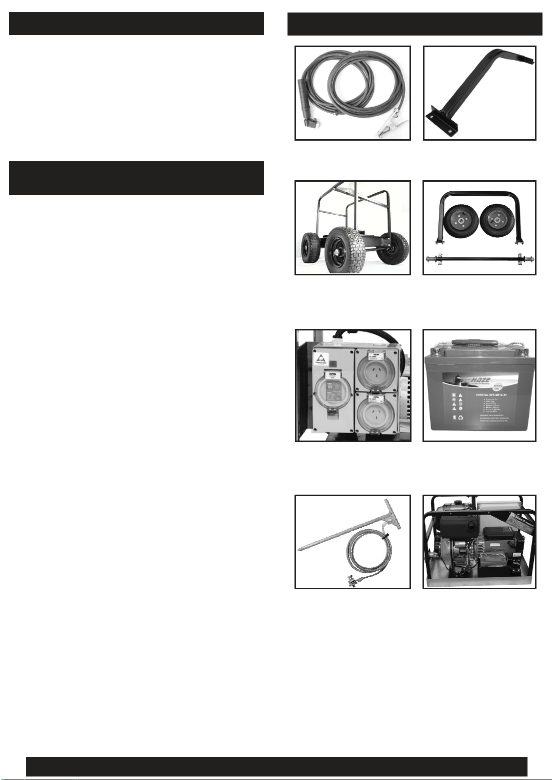
OPTIONAL BATTERY
All electric start sets are tted with a battery
mounting bracket and two leads.
The optional battery is a heavy duty pre-charged
12 VDC maintenance free, sealed gel, deep cycle
battery.
OPTIONS AND ACCESSORIES
ELECTRIC START MODELS
BATTERY INSTALLATION
n Mount the battery into the provided battery
holder. Secure in place by applying a gentle
pressure with the battery holder clamp nuts.
n Making sure the start key is in the off position,
attach the red battery cable to the positive (+)
terminal of the battery. Then attach the black
cable to the negative (-) terminal of the battery.
n The engine will recharge your battery during
normal operating periods. Should your battery
need additional recharging due to lack of use,
a regulated battery charger may be used.
If this is necessary, disconnect the battery
cables before connecting the charger. Ensure
you connect the positive and negative leads
to the corresponding terminals at all times.
Reversal of leads may cause damage to your
equipment.
Welding Leads
(250amp)
Heavy Duty 4 Wheel
Trolley Kit
Earth Leakage &
Weather Proof Outlets
Lifting Eye
2 Wheel Trolley Kit
(4 Wheel Kit Available)
Battery For Electric
Start Models
ADVANCED POWER GENERATING SETS OWNER’S GUIDE4
Earth Stake Containment Tray
Page 5

PETROL ENGINE STARTING
OPERATION
1 Fill crankcase with oil as nominated in
engine manual.
- Place your generator on level ground.
- Remove plug or dipstick
- Fill crankcase slowly to the point of
overowing or correct level on dipstick.
Replace plug or dipstick securely.
2 Pull engine over several times to ensure there
has been no damage during transit.
3 Switch off electrical power outlets.
TO STOP ENGINE
- Move start/stop switch or key to off position
DIESEL ENGINE
STARTING OPERATION
1 Fill crankcase with oil as nominated in
engine manual.
- Place your generator on level ground.
- Remove plug or dipstick
- Fill crankcase slowly to the point of
overowing or correct level on dipstick.
Replace plug or dipstick securely.
4 Turn fuel valve ON.
5 Close choke - push lever in direction of
arrow. It is normal to use the choke when
starting the generator from cold.
6 DO NOT ADJUST THROTTLE SETTING.
It has been factory set and locked at the
correct speed.
7 Set the ON/OFF switch to the ON position.
8 RECOIL/ROPE START - Pull the starter
handle until slight resistance is felt, then pull
briskly. Allow rope to recoil slowly.
ELECTRIC START - Press start button or turn
key to start. Do not operate starter for more
than about 10 seconds at a time.
Allow 60 seconds rest after 2 starting
attempts.
2 Pull engine over several times to ensure there
has been no damage during transit.
3 Set decompression lever if tted
4 Turn fuel valve ON.
5 Set speed control to start setting, 50%
(refer engine owner’s manual)
6 Set the ON/OFF switch to the ON position.
7 RECOIL/ROPE START - Pull the starter
handle until slight resistance is felt, then pull
briskly. Allow rope to recoil slowly.
ELECTRIC START - Press start button or turn
key to start. Do not operate starter for more
than about 10 seconds at a time.
Allow 60 seconds rest after 2 starting
attempts
9 When engine starts, progressively OPEN THE
CHOKE until engine runs smoothly.
10 Allow engine to warm up for about 3 minutes
before applying high loadings to your welder.
11 If engine fails to start after several attempts,
fuel ooding may have occurred. Open the
choke, try starting engine several times, then
repeat starting procedure.
ADVANCED POWER GENERATING SETS OWNER’S GUIDE5
8 Run engine at idle speed for 3 minutes to
allow it to warm up.
9 Set speed control to run position (Max)
before applying load.
(refer engine owner’s manual)
TO STOP ENGINE
- Turn fuel valve to off position, then turn
ignition key to off position.
Page 6
ENGINE & ALTERNATOR SERVICE
IF ENGINE SERVICE OR REPAIR IS NEEDED, CONTACT AN AUTHORISED ENGINE SERVICE
CENTRE. TO SERVE YOU PROMPTLY AND EFFICIENTLY, THE SERVICE CENTRE WILL NEED
THE MODEL, TYPE AND ESPECIALLY THE SERIAL NUMBER OF YOUR ENGINE.
n Each Authorised Service Centre is equipped
with special service tools and trained
mechanics to ensure expert service or repair
on all engines
COMPLY WITH ENGINE OWNERS MANUAL
WHERE IT SPECIFIES MORE FREQUENT SERVICING
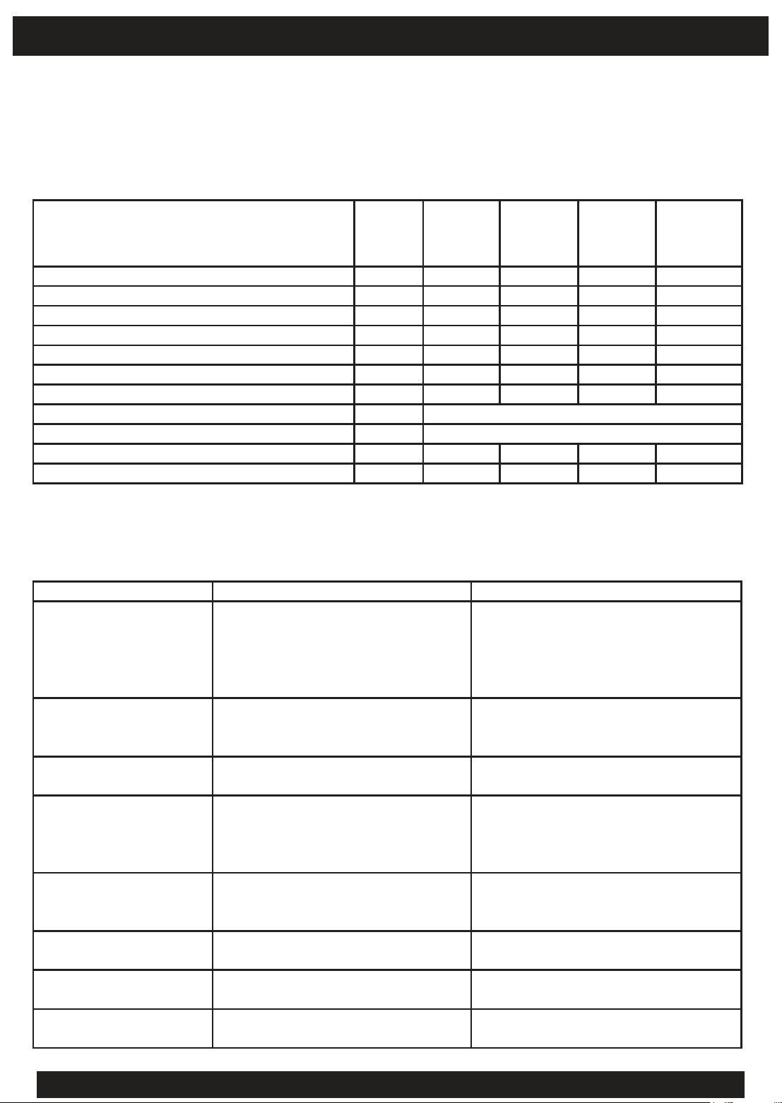
Carry out servicing at indicated month or
operating hours, whichever occurs rst.
Engine oil Inspect Change Change
Air cleaner element Inspect Clean (1)
Fuel lter cleaning Clean
Spark plug maintenance (petrol engines) YES
Tappet clearance adjustment (if applicable) YES
Combustion chamber cleaning YES
Fuel tank cleaning YES
Spark arrester (if applicable) Clean every 100 operating hours.
Fuel line Replace every 3 years.
Alternator exciter brushes (if applicable) Inspect
Battery uid - Electric start (if applicable) Inspect
NOTE: (1) Service more frequently when used in dusty areas.
(2) Daily checks to be performed by the operator, all periodic servicing to be carried out by
an authorised service agent.
n Major engine repairs should not be attempted
without the proper tools and a thorough
knowledge of engine repair procedures.
Daily
First
month or
rst 20
hours
Every
3 months
or 40 hrs
Every
6 months
or 100 hrs
or 300 hrs
Every
year
Welder Alternator Trouble Shooting Guide
Problems Causes Remedies
Engine will not start 1) no/low fuel
2) fuel valve is closed
3) Start/stop switch is on start position
4) Insufcient oil level
5) Faulty low oil sender
Generator excitation failure. 1) Low speed.
2) Faulty condenser.
3) Faulty windings.
High no-load voltage. 1) Speed too high.
2) Condenser with high capacity.
Low no-load voltage. 1) Speed too low.
2) Faulty rotary diodes.
3) Breakdown in windings.
4) Condenser with low capacity.
Correct no-load, but
low loaded voltage.
Correct no-load, but
high loaded voltage.
Unstable voltage. 1) Loose contacts.
Noisy Generator. 1) Damaged bearings.
1) Low loaded speed.
2) Load too large.
3) Condenser with low capacity.
1) High loaded speed. Check and adjust RPM.
2) Uneven rotation.
2) Poor engine-alternator coupling.
Fill fuel tank
Open fuel valve
Set to start position
Add oil to the correct level
See authorised repair agent
Check and adjust to factory
Check and replace.
Check windings resistance.
Check and adjust RPM.
Check and replace.
Check and adjust RPM.
Check and replace.
Check windings resistance.
Check and replace.
Check and adjust RPM.
Check and change.
Check and replace.
Check connections.
Check for uniform RPM.
Replace.
Check and adjust.
ADVANCED POWER GENERATING SETS OWNER’S GUIDE6
Page 7

WELDER SERVICE
Your Advanced Power welder is designed to provide many years of trouble free operation. All servicing of
the welder must be carried out by an Authorised Service Centre.
WELDING
ENSURE ALL A.C. AUXILIARY AND BATTERY CHARGING CABLES ARE DISCONNECTED COMPLETELY
FROM THE TERMINALS ON THE WELDER-GENERATOR BEFORE WELDING.
The Selector Knob on the Control Panel allows adjustment of welder amperage to provide optimum current
for each size electrode and type of job. If the job requires less amps for satisfactory welding, connect
the cable to the low terminal and then adjust the Selector Knob to provide the correct current. If the job
requires more amps, connect the cable to the high terminal and then adjust the Selector Knob to obtain the
current required.
A thermal overload protection device is tted which intervenes in case of overload by cutting off welder
output. After approximately 1 minute, normal operation will be automatically restored.
Allow your generator/welder to warm up (approx 3 minutes) before you start welding and after any welding
allow your generator welder to run (approximately 1 minute) to cool down before turning it off.
WELDING TERMINALS
The female terminals on the welder accept the loose supplied male terminals which should be tted to the
ends of the welder cables.
The primary welding cable (connected to the rod holder) must be plugged into one of the welding outlets
as marked. These relate to the maximum welding current available from that particular outlet and are
designed to correspond with the control setting ranges on the Control Panel.
For welding, the “EARTH” terminal must be connected to the earth cable which at all times must be
clamped to the material been welded.
DO NOT ATTEMPT TO WELD CONTINUOUSLY. THE THERMAL OVERLOAD PROTECTION DEVICE WILL
INTERVENE. IF THIS OCCURS REGULARLY IT MAY CAUSE DAMAGE TO THE UNIT.
1 PHASE A.C. GENERATOR POWER
ENSURE THE WELDING CABLES ARE DISCONNECTED COMPLETELY FROM THE TERMINALS ON THE
WELDER/GENERATOR BEFORE USING A.C. POWER.
Set the Selector Knob to the “GEN” or (Generator) position and then plug the appliance cable into the
normal A.C. socket provided.
Refer to the settings shown on the Control Panel.
DO NOT OPERATE 2 OPTIONS AT ONE TIME.
DO NOT REMOVE ANY BATTERY CONNECTIONS WHILE ENGINE IS RUNNING.
BATTERY CHARGING (If Fitted)
Your welder generator is tted with a 12 VDC trickle charger. To charge your battery, ensure your welder
generator is turned off and connect the battery using appropriate battery leads. Make sure the red lead
connects to the positive (+) terminal of the battery and black to the negative (-). Start your welder generator
and your battery is now been charged. Not suitable for batteries above 100 amp hour. NOTE, output is not
regulated and connection of small batteries for long periods of time may cause damage to the battery.
ADVANCED POWER GENERATING SETS OWNER’S GUIDE7
Page 8
OPERATOR SAFETY
WELD ‘n’ WORK
A welder generator set
must not be transported
with any fuel in the fuel
tank or carburetor in
any vehicle. Fumes are a
health hazard and there is
always the danger of re.
NOTE: ALL NUTS AND BOLTS
SHOULD BE CHECKED
FOR TIGHTNESS ON A
REGULAR BASIS.
WELDER GENERATOR
FINAL QUALITY INSPECTION
MODEL ............................ ALT ..................
SERIAL No ........................ DATE ..............
Engine p
Alternator / Welder p
Standard/Weather-proof Outlets p
Mounting Frame p
A/V Mounts p
Nameplate Stamped & Fitted p
Engine to Alternator Assembly p
Engine/Alternator to Frame Assembly p
Paint Finish p
Test Procedure p
Fuel & Oil Drained p
Labels Correct & Secure p
All Bolts Tensioned p
Nyloc Nuts Correctly Fitted p
All Documents Included
Electrical Connections p
Battery Charge & Fuse Protection p
p
Signed: ..............................................................
This certicate to be completed and signed by the person
responsible for the nal test and inspection procedure and
packed with the completed generator set.
M+H Power Systems Pty Ltd
10 Williamson Road, Ingleburn, NSW 2565
T: 1300 733 004
F: 1300 733 005
E: [email protected]
ABN 96 051 792 833
www.mpower.com.au
APOGwnw-500E 9-11
 Loading...