

Advanced Network Devices IPSWD-FM-RWB Installation Guide
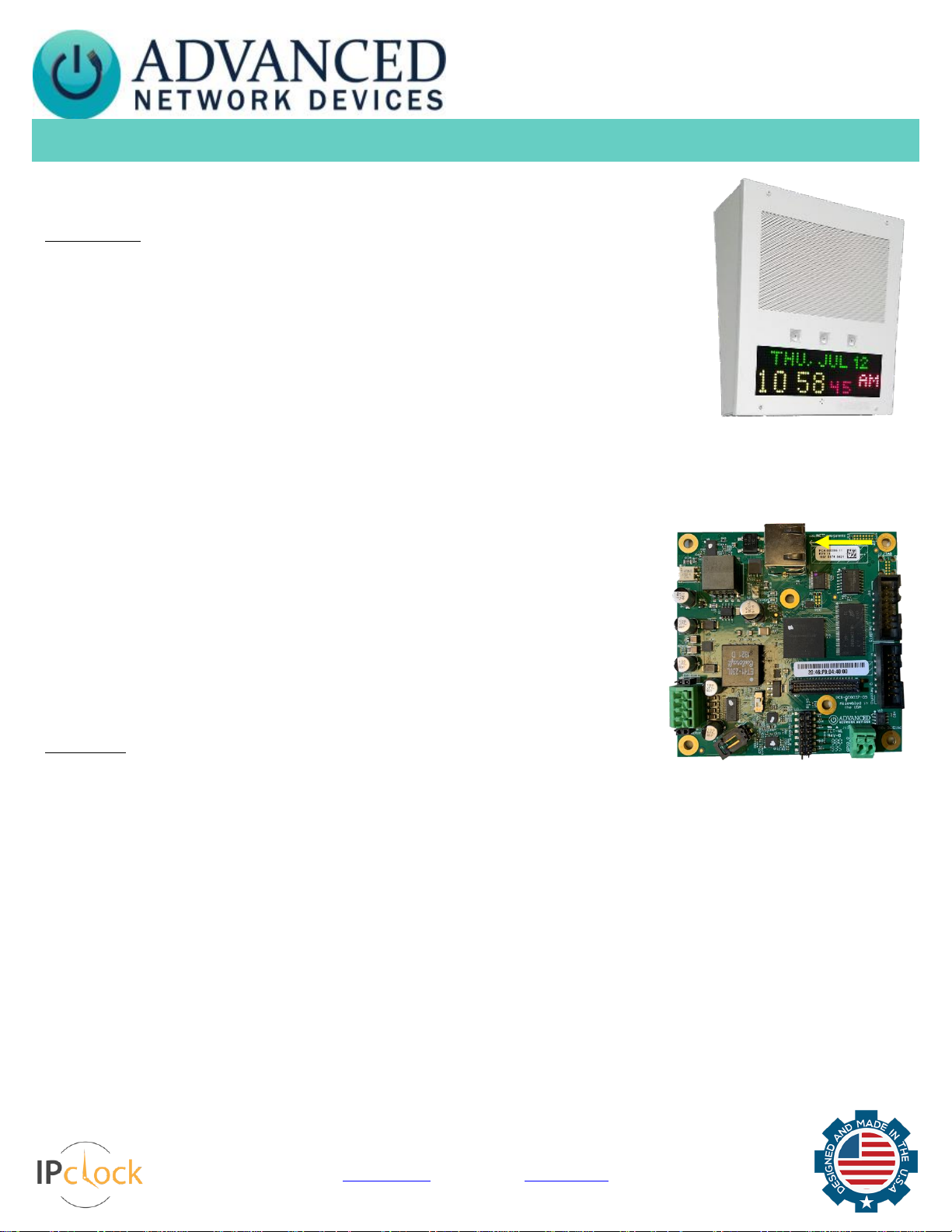
IP Speaker with Display
(IPSWD-RWB/IPSWD) Installation
Advanced Network Devices • 3820 Ventura Dr. Arlington Hts. IL 60004
tech@anetd.com • 847-463-2237 • www.anetd.com
Version 1.5 • 4/18/19
INSTALLATION INSTRUCTIONS
The IP Speaker with Display ships with a ferrite. If concerned with line performance, wrap the CAT5 or
CAT6 Ethernet cable around ferrite once and clamp shut.
Surface Mount
For surface mount installation, use IPS-SM1 surface mount rear enclosure as follows:
1. Remove rear enclosure (IPS-SM1) from packaging.
2. If running conduit or wiremold to the enclosure, break open the top or bottom wiremold
knockout.
3. Place enclosure or mounting template on wall surface, over the access port for the Ethernet cable
(CAT5 or CAT6) if not running cable along the exterior wall, and mark the desired hole pattern to
be drilled using the holes provided in the enclosure surface back.
4. Set enclosure aside and drill pilot holes for anchors or screws to be used on mounting surface.
5. Install anchors (not provided) if used.
6. Feed Ethernet cable through access port in the enclosure and then fasten the enclosure to the wall surface at the prepared
locations using screws (not provided). Tighten securely.
7. If using wiremold, complete the Ethernet cable run to the enclosure.
8. Remove front baffle assembly, the IPSWD or IPSWD-RWB, from packaging.
9. Remove bag of screws from rear speaker magnet.
10. Complete any additional wiring for accessories, then connect the Ethernet cable to
Ethernet jack J3 on the circuit board.
11. Place front baffle assembly over the enclosure taking care not to let the bottom of the
circuit board strike the bottom lip of the enclosure. Thread the four provided screws
through the baffle and into the enclosure at the four corners of the baffle. Tighten securely.
Flush Mount
For flush mount installation, use IPS-FM1 flush mount rear enclosure as follows:
1. Remove rear enclosure (IPS-FM1) from packaging.
2. If wall surfaces are already installed, place enclosure on wall surface adjacent to a stud, and trace the perimeter of the enclosure.
Cut a hole in the wall along the traced perimeter.
3. Break open the appropriate knockout for the conduit or cable run.
4. Place one side of enclosure on a stud and mark desired pilot holes within the 3 slots provided.
5. Set enclosure aside and drill pilot holes for the screws to be used on the mounting surface.
6. Place enclosure on the stud over the pilot holes and thread screws (not provided) into the stud. Tighten securely.
7. Complete the Ethernet cable run into the enclosure.
8. Remove front baffle assembly, IPSWD or IPSWD-RWB, as well as the bag of screws from the rear speaker magnet.
9. Complete any additional wiring for accessories, then connect the Ethernet cable to Ethernet jack J3 on the circuit board.
10. Place front baffle assembly over the enclosure taking care not to let the bottom of the circuit board strike the bottom lip of the
enclosure. Thread the four provided screws through the baffle and into the enclosure at the four corners of the baffle. Tighten
securely.
J3
IP Speaker with Display
(IPSWD-RWB/IPSWD) Installation
Advanced Network Devices • 3820 Ventura Dr. Arlington Hts. IL 60004
tech@anetd.com • 847-463-2237 • www.anetd.com
Version 1.5 • 4/18/19
DEVICE OPERATION
1. Connect the other end of the network cable to a PoE (Power over Ethernet) network switch, or a PoE injector, on a network with a
DHCP server. Find some supported equipment options listed at https://www.anetd.com/project-resources/prepare-for-installation/
2. If properly installed, the unit should boot and show the time within 30 seconds. See boot process below.
3. Consult the IPClockWise User Manual (see https://www.anetd.com/portal/ ) or third-party software guide for further instructions
on sending audio and text to the device.
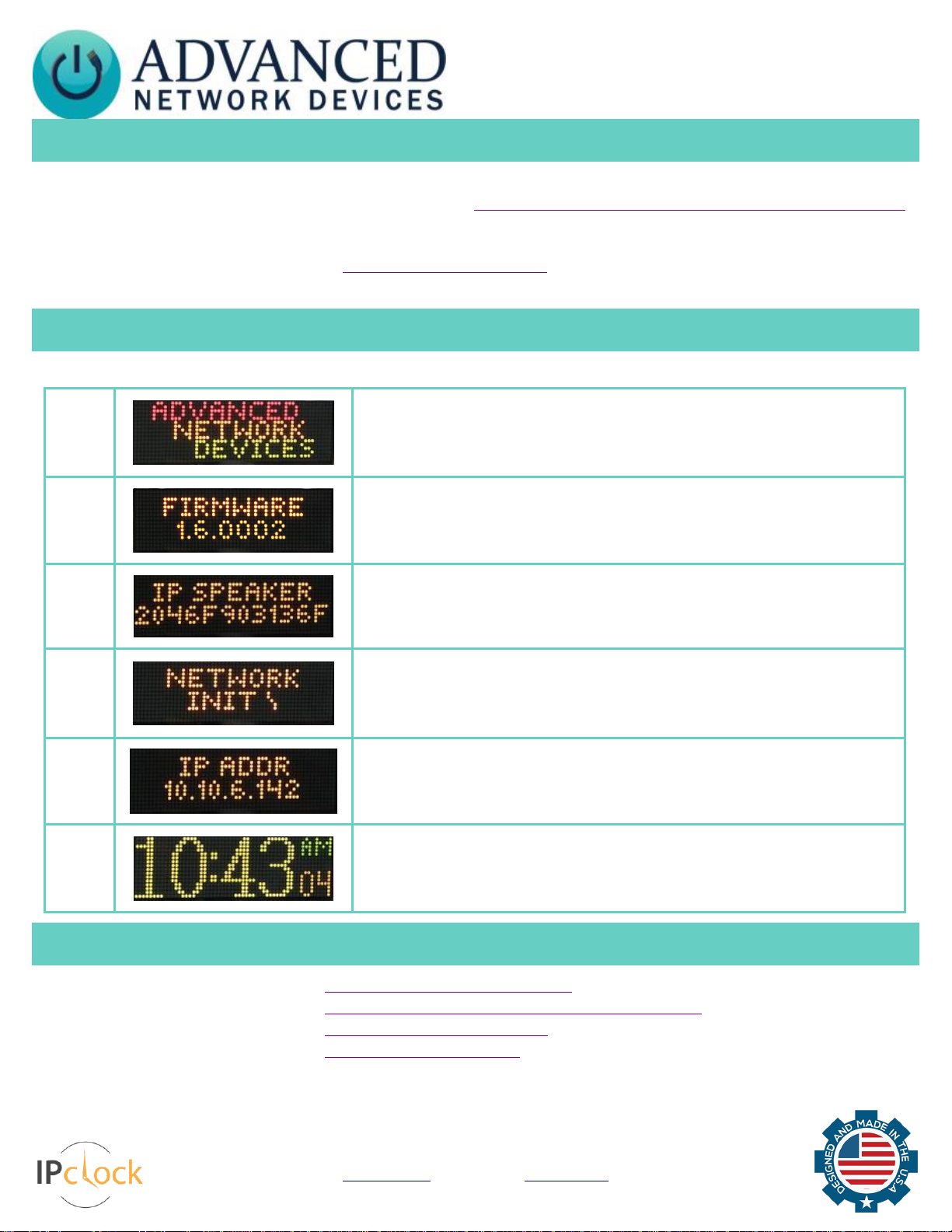
BOOT SEQUENCE
When first powered, if properly installed, the device should boot, and then display the time as follows:
1
The first screen you will see. This screen should appear within 1-2 seconds of
powering on the device. The AND jingle should playback over the speakers.
2
Indicates the current firmware equipped with the device.
3
Indicates the network MAC address of the device (configured at the factory).
4
Indicates that the device is looking for a DHCP server, among other things. If the boot
process hangs in this state, check for a possible network problem (cable, switch, ISP,
DHCP, etc.)
5
Indicates the IP address of the device. DHCP assigns this network-specific address.
Otherwise, the static address will appear if configured as such. An audio beep should
playback over the speakers during this stage.
6
Once all initialization completes, the time will display. If just a colon displays, it
cannot find the time. Check the NTP server settings, and check that the internet
connection is working.
ADDITIONAL RESOURCES
User Support: https://www.anetd.com/user-support/
Technical Resources: https://www.anetd.com/user-support/technical-resources/
AND Limited Warranty: https://www.anetd.com/warranty/
AND Legal Disclaimer: https://www.anetd.com/legal/
 Loading...