

http://www.BDTIC.com/AMS
Advanced AMS236/AMS336
Monolithic VOLTAGE REFERENCE DIODE
Systems
RoHS compliant
FEATURES APPLICATIONS
• Low Temperature Coefficient • Power Supplies
• Wide Operating Current Range • Instrumentation
• Guaranteed Temperature Stability • 8 Bit A/D, D/A Reference
• Max. 0.6Ω Dynamic Impedance (A grade) • Current Loop Measurement and Control Systems
• ±1% Initial Tolerance Available • Reference for 5V Systems
GENERAL DESCRIPTION
The AMS236/AMS336 are precision band-gap voltage reference diodes. These voltage reference features a very low dynamic
impedance and good temperature coefficient, operating over a wide current range of 400µA to 10mA. On-chip trimming is
used to provide tight tolerance and minimize temperature drift. A third terminal allows the reference vo ltage to be trimmed
±5%.
The AMS236/AMS336 are used as a precision 2.5V low voltage reference for digital voltmeters, power supplies or op amp
circuitry, and the 2.5V make it easy to obtain a stable reference from 5V logic supplies.
The AMS236 is rated for operation over -25°C to +85°C while the AMS336 is rated over a 0°C to 70°C temperature range.
The AMS236/AMS336 are available in TO-92 and SO-8 packages.
ORDERING INFORMATION:
TOL. PACKAGE TYPE OPERATING
TO-92 8 LEAD SOIC
±25mV AMS236AN AMS236AS
±50mV AMS236BN AMS236BS
±50mV AMS336AN AMS336AS
±100mV AMS336BN AMS336BS
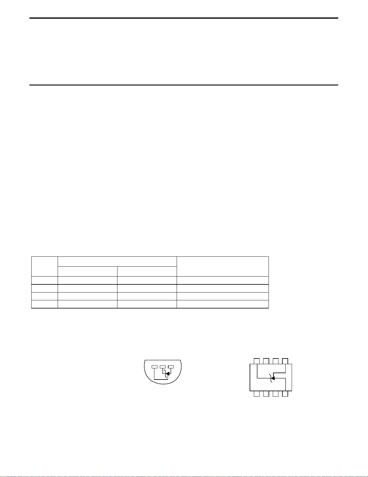
PIN CONNECTIONS
TO-92 8L SOIC
Plastic Package (N) SO Package (S)
TEMPERATURE RANGE
-25°C to +85°C
-25°C to +85°C
0°C to 70°C
0°C to 70°C
123
N/C ADJN/C
+
756
Bottom View
12843
N/C N/C N/C
Top View
-

http://www.BDTIC.com/AMS
AMS236/AMS336
ABSOLUTE MAXIMUM RATINGS (Note 1)
Reverse Current 15mA Storage temperature
Forward Current 10mA Soldering information (25 sec)
Operating Temperature Range
AMS236
AMS336
-25°C to
0°C to
+85°C
+70°C
-55°C to +150°C
°C
265
ELECTRICAL CHARACTERISTICS
Electrical Characteristics at IR = 1 mA, and TA = +25°C unless otherwise specified.
Parameter
Reverse Breakdown Voltage
Reverse Dynamic Impedance f = 100Hz 0.2
Reverse Breakdown Voltage
Change with current
Temperature Stability
Long Term Stability (Note 4)
Conditions
400µA ≤I
-25°C ≤ T
T
A
T = 1000 Hr
≤10mA
R
≤ +85°C
A
=25°C±0.1°C
AMS236A
Min Typ Max
2.475 2.500 2.525 2.450 2.500 2.550 V
0.6
0.4
2.6 3 6
3.5 9 3.5 9 mV
20 20 ppm
1
10
AMS236B
Min Typ Max
0.2
0.4
2.6 3 6
0.6
10
Units
Ω
1
mV
ELECTRICAL CHARACTERISTICS
Electrical Characteristics at IR = 1 mA, and TA = +25°C unless otherwise specified.
Parameter
Reverse Breakdown Voltage
Conditions
AMS336A
Min Typ Max
2.450 2.500 2.550 2.400 2.500 2.600 V
AMS336B
Min Typ Max
Units
Reverse Dynamic Impedance f = 100Hz 0.2
0.4
Reverse Breakdown Voltage
Change with current
Temperature Stability
Long Term Stability (Note 4)
400µA ≤I
0°C ≤ T
T
T = 1000 Hr
R
≤ 70°C
A
=25°C±0.1°C
A
≤10mA
2.6 3 10
1.8 6 1.8 6 mV
20 20 ppm
1.0
1.4
12
0.2
0.4
2.6 3 10
1.0
1.4
12
Ω
mV
Note 1: Absolute Maximum Ratings indicate limits beyond which damage to the device may occur. Operating Ratings indicate conditions for which the
device is intended to be functional, but do not guarantee specific performance limits. For guaranteed specifications and test conditions, see the Electrical
Characteristics
Note 2: For elevated temperature operation, T
. The guaranteed specifications apply only for the test conditions listed.
max is:
j
AMS236 +125°C
AMS336 +100°C
Thermal Resistance TO-92 SO-8
ϕ
(junction to ambient)
JA
Note 3: Parameters identified with boldface type apply at temperature extremes. All other numbers apply at T
170°C/W (0.125” leads) 165°C/W
= TJ = 25°C.
A
Note 4: Temperature stability for the AMS236/336 family is guaranteed by design. Design limits are guaranteed (but not 100% production tested) over the
specified temperature and supply voltage ranges. These limits are not used to calculate outgoing quality levels. The average temperature coefficient is defined
as the maximum deviation of reference voltage at all measured temperatures between the operating T
MAX and TMIN
, divided by T
MAX
- T
MIN
.

http://www.BDTIC.com/AMS
AMS236/AMS336
TYPICAL PERFORMANCE CHARACTERISTICS
Reverse Characteristics
-1
10
A)
µ
-2
10
-3
10
TJ = +85° C
-4
10
REVERSE CURRENT (
-5
10
0.5
1.0 1.4
REVERSE VOLTAGE (V)
TJ = +25° C
TJ = -25° C
1.8 2.2
2.6
Reverse Voltage Change
3.5
3.0
2.5
2.0
1.5
1.0
0.5
0
REVERSE VOLTAGE CHANGE (mV)
0
2
68
4
REVERSE CURRENT (mA)
Response Time
2.5
OUTPUT
2.0
1.0
0
6
VOLTAGE SWING (V)
~
~
2.5k
INPUT
OUTPUT
INPUT
0
10
02 6
48
TIME (
µ
s)
TYPICAL APPLICATIONS
2.5V Reference Wide Input Range Reference 2.5V Reference with Minimum Temperature Coefficient
~
~
10V
2.5k
2.5V
AMS336
Precision Power Regulator with Low Temperature Coefficient
AMS1085
IN
V
IN
OUT
ADJ
AMS336
1.2k
1N457
10k*
1N457
V
R1
375
R2
2k
OUTPUT
ADJUST
OUT
V
3.5 TO 40V
IN
5V
2.5k
68
AMS336
V
= 2.5V
OUT
AMS336
1N914*
10k†
1N914*
† Adjust to 2.50V
* Any silicon signal diode
Trimmed 2.5V Reference with Temperature Coefficient
Independent of Breakdown Voltage
10V
5k
10k*
AMS336
*Does not affect Temperature Coefficient
TRIM

http://www.BDTIC.com/AMS
PACKAGE DIMENSIONS inches (millimeters) unless otherwise noted.
3 LEAD TO-92 PLASTIC PACKAGE (N)
0.060±0.005
(1.524±0.127)
DIA
0.180±0.005
(4.572±0.127)
0.180±0.005
(4.572±0.127)
0.90
(2.286)
NOM
0.060±0.010
(1.524±0.254)
AMS336
0.140±0.010
(3.556±0.127)
10°
NOM
N (TO-92 ) AMS DRW# 042391
0.500
(12.70)
MIN
0.050±0.005
(1.270±0.127)
0.050
(1.270)
MAX
0.016±0.003
(0.406±0.076)
UNCONTROLLED
LEAD DIMENSIONS
5° NOM
0.015±0.002
(0.381±0.051)
8 LEAD SOIC PLASTIC PACKAGE (S)
0.189-0.197*
(4.801-5.004)
87 65
0.228-0.244
(5.791-6.197)
0.150-0.157**
(3.810-3.988)
12 34
0.053-0.069
(1.346-1.752)
0.014-0.019
(0.355-0.483)
*DIMENSION DOES NOT INCLUDE MOLD FLASH. MOLD FLASH
SHALL NOT EXCEED 0.006" (0.152mm) PER SIDE
**DIMENSION DOES NOT INCLUDE INTERLEAD FLASH. INTERLEAD
FLASH SHALL NOT EXCEED 0.010" (0.254mm) PER SIDE
0.050
(1.270)
TYP
0.004-0.010
(0.101-0.254)
0.008-0.010
(0.203-0.254)
0.010-0.020
(0.254-0.508)
0.016-0.050
(0.406-1.270)
x 45°
0°-8° TYP
S (SO-8 ) AMS DRW# 042293
 Loading...