

Page 1
pro
EGOpro
Safety Move
Safety aid
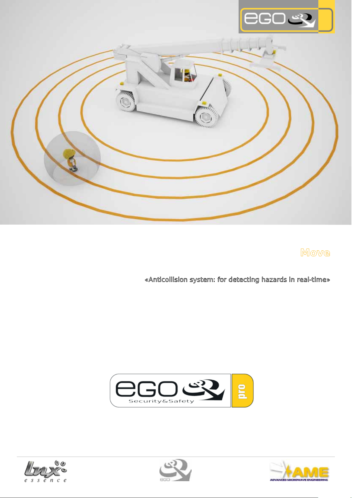
«Anticollision system: for detecting hazards in real-time»
INSTALLATION AND OPERATING MANUAL
Manuale EGOpro Safety Move HW EN V02_16
Page 2

Index
2
1. Introduction.............................................................................................................................................................3
2. Operating the system..............................................................................................................................................4
3. Parts of the system..................................................................................................................................................5
4.System conguration................................................................................................................................................6
4.1 Sensors for vehicle type
5. Fitting and Positioning.............................................................................................................................................10
5.1 Sensor
5.1.2 Mechanical sensor tting
5.1.3 Positioning the sensors
5.1.4 Sensor direction
5.2 CPU
5.2.1 Mechanical CPU tting
5.2.2 CPU Positioning
5.3 Splitter
5.3.1 Splitter Positioning
6. Electrical connections............................................................................................................................................14
6.1 Power supply
6.2 Data Bus
6.2.1 RJ45 Terminations
6.3 Relay Output
6.3.1 Relay
6.3.4 Relay operating mode
7. Sensor ID allocation................................................................................................................................................17
8. Optional EGOpro Safety MOVE................................................................................................................................18
8.1 GPS
8.2 Wi- Transfer
pro
8.3 Vehicle/Vehicle Anticollision
8.3.1 Reector power supply
8.3.2 Positioning and installation of the Reectors
9. Speed measurement module ................................................................................................................................22
10. Active PPE provision.............................................................................................................................................23
10.1 Active harness
10.2 Active helmet
11. Statements...........................................................................................................................................................24
12. Data sheet............................................................................................................................................................24
Page 3
3
1. Introduction
EGOpro Safety Move is a safety aid system that, due to the sensors placed on the vehicle and the innovative active
PPE worn by the worker, enables drivers of moving vehicles such as forklifts, excavators etc....to detect via a display
inside the cabin, the presence and position of a worker (or of other vehicles) that, are located in actual hazardous
conditions at ground level.
The features that set EGOpro Safety Move apart from competitor systems are:
-Long-range: the system is capable of managing a very wide detection range (beyond 30m) to detect and indicate the hazard at an appropriate distance at all times with respect to the braking distance required to prevent the
collision of the vehicle at any speed.
- Selectivity: the system is capable of warning the operator of the presence of employees tted with an LNX
tag, therefore avoiding false alarms due to other stationary obstructions.
sence
-Flexibility: the system creates an ideal environment for any application type due to the means of adjusting the
transmitted power and therefore the size of the control area (safety bubble) at a radius of 360° around the vehicle,
thus resolving blind spot issues and also intervening automatically in the event of distractions and driver fatigue.
-Data logging: an intelligent unit that constantly collects and analyses data recorded for the purpose of building
an actual map of the critical zones of the working area, advising corporate security ocers of the precautions and
that it is advantageous to adopt in order to restrict hazardous zones.
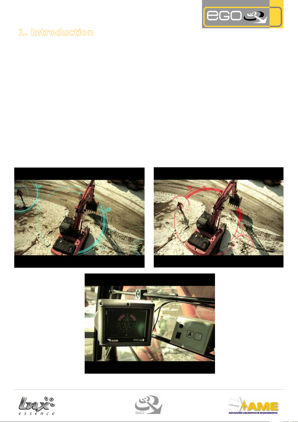
Example of operation
pro
es-
Vehicle in use with operators at ground level
Hazard and position warning in the driver's cab
Operators in the hazardous zone surrounding the vehicle
Page 4
4
2. Operating the system
pro
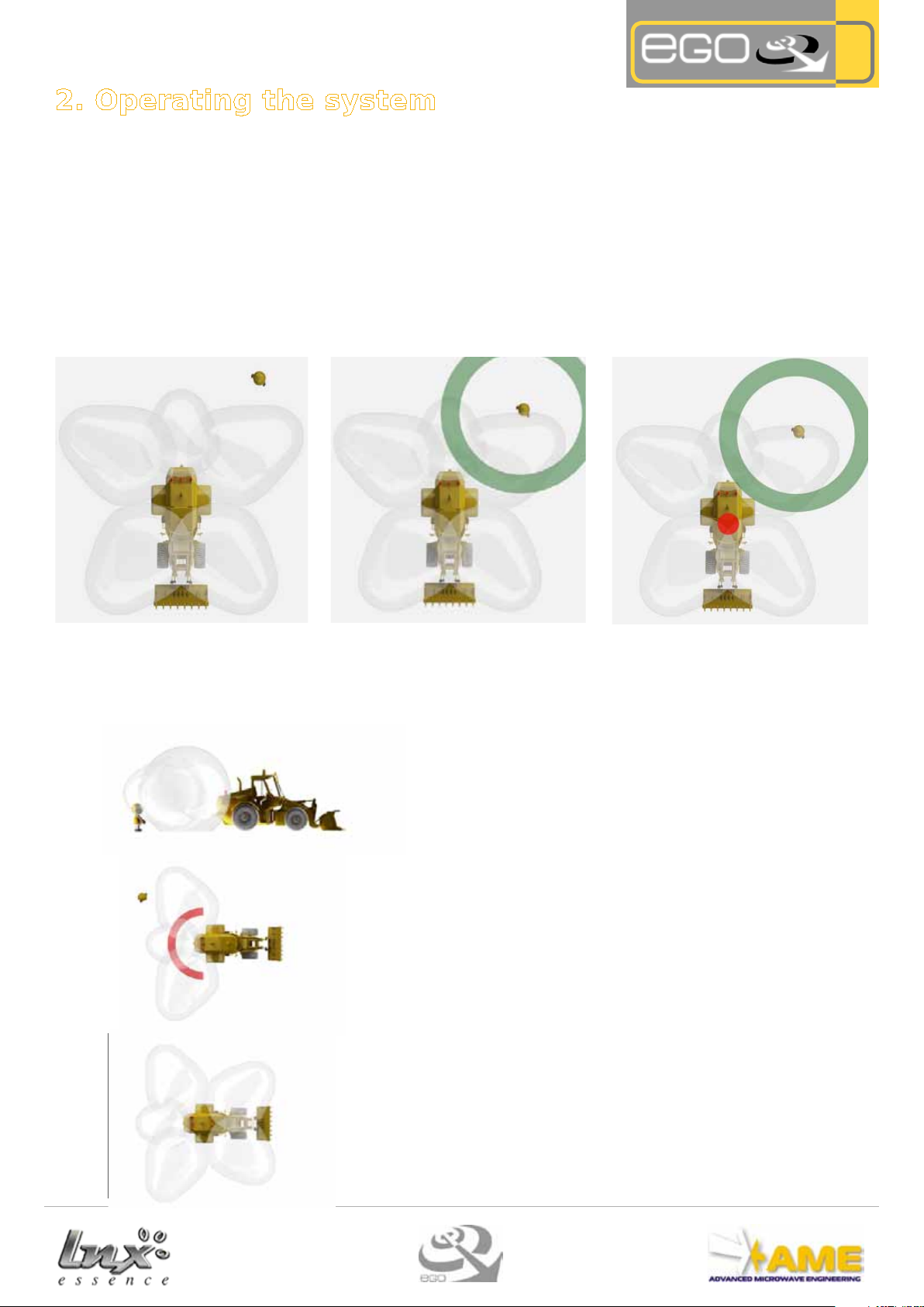
> ACTIVATION AREA
The system is congured depending on
the client's needs, by placing satellite antennas in order to cover the area that we
wish to monitor.
In the 5 antenna conguration shown in
diagram (Fig. 1) the system manages to
obtain a 360° radius coverage around
the vehicle.
>
TAG ACTIVATION.
When the employee, tted with Tag,
comes into contact with the active protection "SAFETY BUBBLE" (activation zone gener-
ated by the satellite antenna) , the Tag awakens
and transmits a signal to the satellite antenna which has detected it. (Fig. 2)
This warns of the worker's presence
around the moving vehicle and especially his position relative to the vehicle.
> ALARM ACTIVATION
The driver will therefore be alerted not
only to the presence of the employee
around the vehicle, but also of his position via the "synoptic set". (Fig. 3)
Fig. 1
Fig. 2
Fig. 3
2.1 Activation areas
The system is exible and modular and it allows only a possibly hazardous area to be monitored in accordance with operating
needs. The choice of the number of satellite antennas depends on the coverage required. The maximum number of satellite an-
tennas that can be installed on the vehicle is eight. We can see the three "conguration types" below that we have identied as
Rear control area
In this case coverage is obtained only at the rear part of the vehicle by
installing a single satellite antenna at the back. (Fig. 9)
Fig. 9
180° Radius control area
A 180° radius coverage is carried out with the installation of three antennas. (Fig.10)
Fig. 10
360° Radius total control area
Five antennas are installed, in this case to acquire a complete coverage
of 360°. (Fig.11)
Fig. 11
Page 5
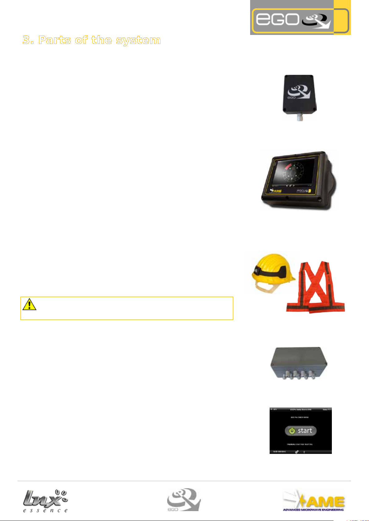
Fig. 6
5
3. Parts of the system
> SENSOR
P LX SATMOVETOUCH
The satellite antenna (Fig. 4) has the task to activate the Tags near the vehicle and
detect their presence, transmitting the information to the on-board display.
Each vehicle can be equipped with a maximum of 8 displays, mounted outside the
vehicle, which generate the activation area for the Tags. This area is completely
controllable: both in terms of positioning the displays and adjusting the transmitted
power.
> CENTRAL UNIT (CPU)
P LX SIN MOVE
The synoptic set (Fig. 5), to be mounted in the cabin, will have all the eects of a PC
touch screen that will allow the driver and authorised employees to have the following information:
The events to be memorised/monitored are summarised as:
• System conguration access
• System clock modication
• Satellite parameters modication (Power, Vehicle ID, etc.)
• (Person) Tag detection
• Tag Code
• Tag Detection Time
• Log (events time) that can be DOWNLOADED
pro
Fig. 4
Fig. 5
> TAG
P LX TAG MOVE
Every worker who is in the working area of moving vehicles, should be tted with two
Tags, there are two possible congurations:
1) Helmet with integrated Tags.
2) High visibility harnesses in the rear part and one in the front part positioned in the
appropriate pockets.
NOTE: the performances of the integrated version on the helmet, due to harmonising electromagnetic
behaviour, are better than those obtained by the integrated version on the high visibility harnesses.
A.M.E. always advises to use the integrated version on the helmet where possible. Furthermore, the two
versions perform dierently: the coexistence of both versions on the same operating site will entail different performances of the EGOpro Safety MOVE system.
> SPLITTER
The Splitter (Fig.7) connects the data bus between the CPU and the satellite antennas
and it can connect up to 8 satellite antennas.
> CHECKPOINT
P LX CHECKMOVE 02
The checkpoint veries the Tags work properly and consequently the active PPE (for
e.g. it conducts a daily check on the charge of batteries) supplied to the workers.
It is usually installed in allocated areas and the dressing room or in access areas to
the construction site or business so as to conduct the check before starting the working day.
The device stores and historically views data regarding tests on devices provided and
it can be connected to a ow control system like a turnstile, for example.
Fig. 7
Fig. 8
Page 6
6
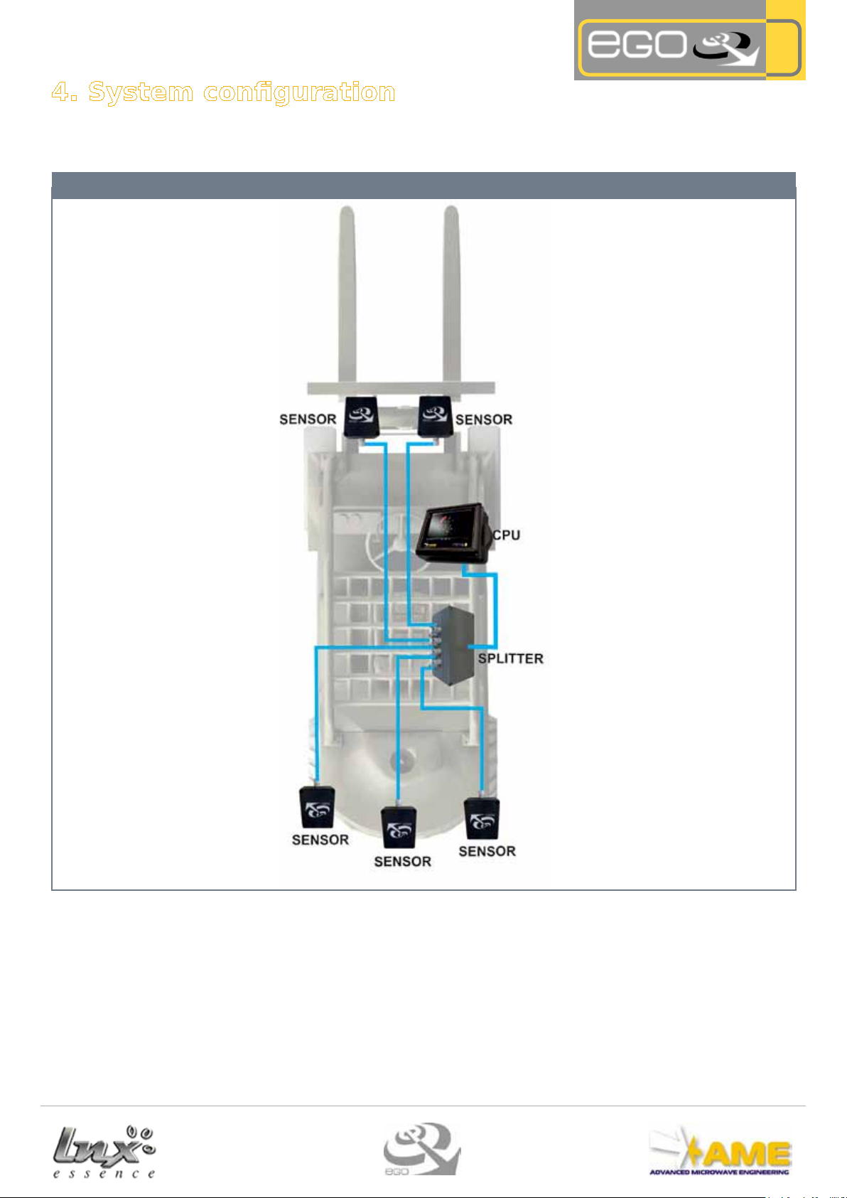
4. System conguration
Congurations: Depending on the vehicle type, its dimensions and level of coverage required (90°,180°,360°, etc.) it is possible to
use up to 8 sensors on the vehicle.
5 SENSORS conguration
pro
Fig. 16 - Conguration -
The sensors and the CPU should be connected to the splitter via a Data Bus.
SENSOR: the sensors are placed outside the driver's cab on the vehicle facing the operator at ground level.
CPU: is installed inside the cab in a position that can be seen by the driver and at the same time it does not restrict his view
SPLITTER: the splitter is positioned in the driver's cab, but it does not matter whether it is seen as it is used to connect the
sensors to the controller.
Page 7
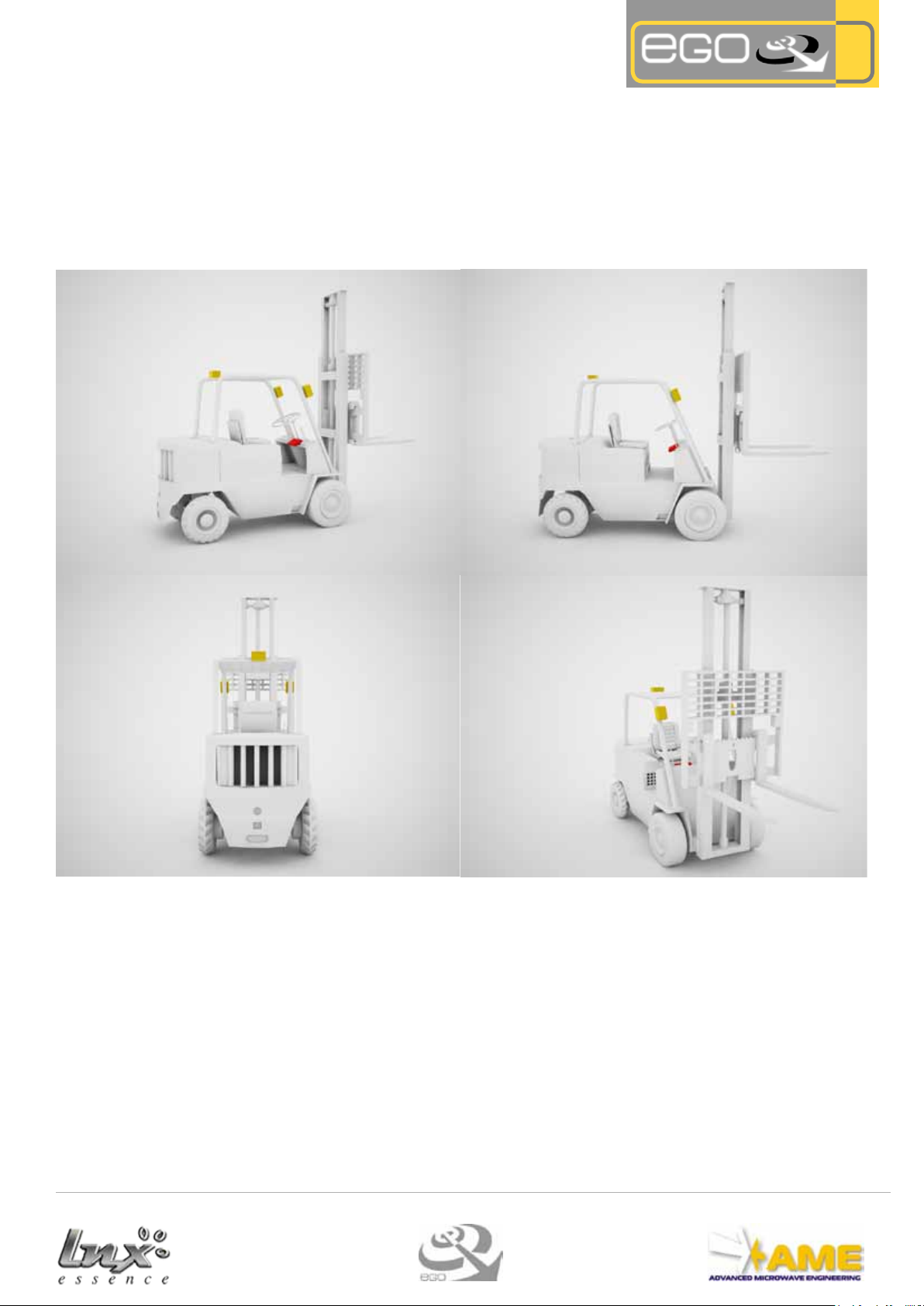
4.1 Sensors for vehicle type
Please bear in mind that the pictures that we going to show are merely approximate, we can identify the possible congurations of
the EGOpro Safety MOVE system that acquire complete coverage (for four vehicle types).
Each conguration can be optimised depending on applicable requirements and therefore the actual hazardous areas to be covered.
The maximum number of sensors per conguration is 8 .
Forklift
pro
2 front sensors
1 rear sensor
7
Page 8
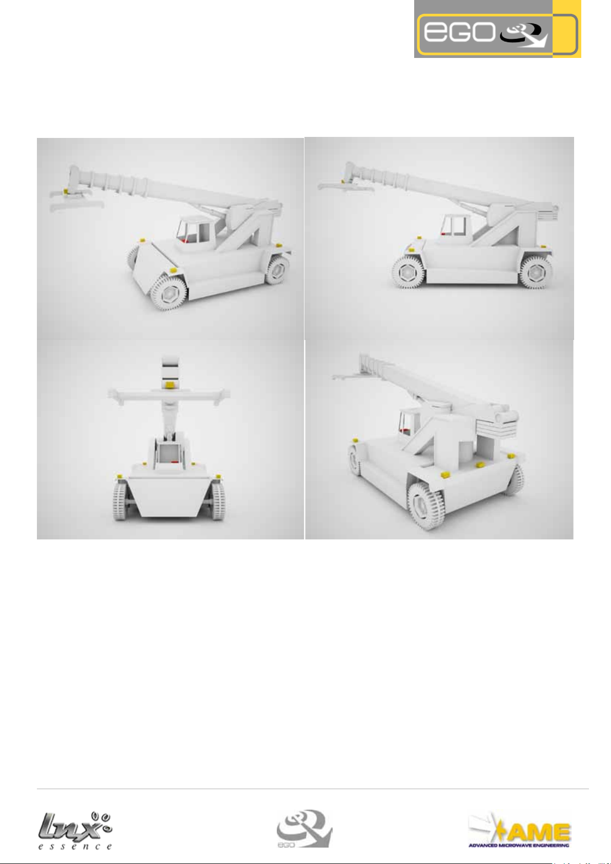
Reach stacker
pro
3 front sensors
3 rear sensors
8
Page 9

straddle carrier
pro
4 right side sensors
4 left side sensors
9
Page 10

5. Fitting and positioning
10
5.1 Sensor
The number and position of the sensors to be installed depends on the coverage area
and vehicle type.
pro
All the sensors are tted with a mechanical plate and joint to facilitate installation.
Fig. 17 - Plate -
Fig. 17 - Sensor -
In hostile working conditions, such as salty areas
(ports), it is advisable to
use Souriau type connec-
tions.
It is necessary
the positioning procedures
in the appendix.
to follow
Fig. 17 - Joint -
5.1.2 Mechanical sensor tting
Once the sensors location has been decided (following the instructions on page 5-6) it will be necessary to carry out a mechanical
fitting of the vehicle, in order to install the sensors. The mounting plate on each sensor and the mechanical joints provided with the
system facilitate mounting onto the vehicle.
To attach the sensor to the vehicle, a clamp (not supplied) should be fitted with 3 holes (Ø4mm) 4mm in diameter,
17.5mm apart. The clamp should be attached to the vehicle so that the sensor creates an angle of about 20° relative to the
axis (turned slightly outwards).
There are mainly two installation stages of the sensor and they must be carried out in this order:
1_ MECHANICAL FITTING: Create an anchoring clamp (not supplied) on the vehicle where the joint can be attached (3 holes (Ø4mm)
4mm in diameter, 17.5mm apart).
2_ ATTACHMENT: Attach the sensor already fitted with the plate to the joint that has already been anchored to the vehicle.
Page 11
11
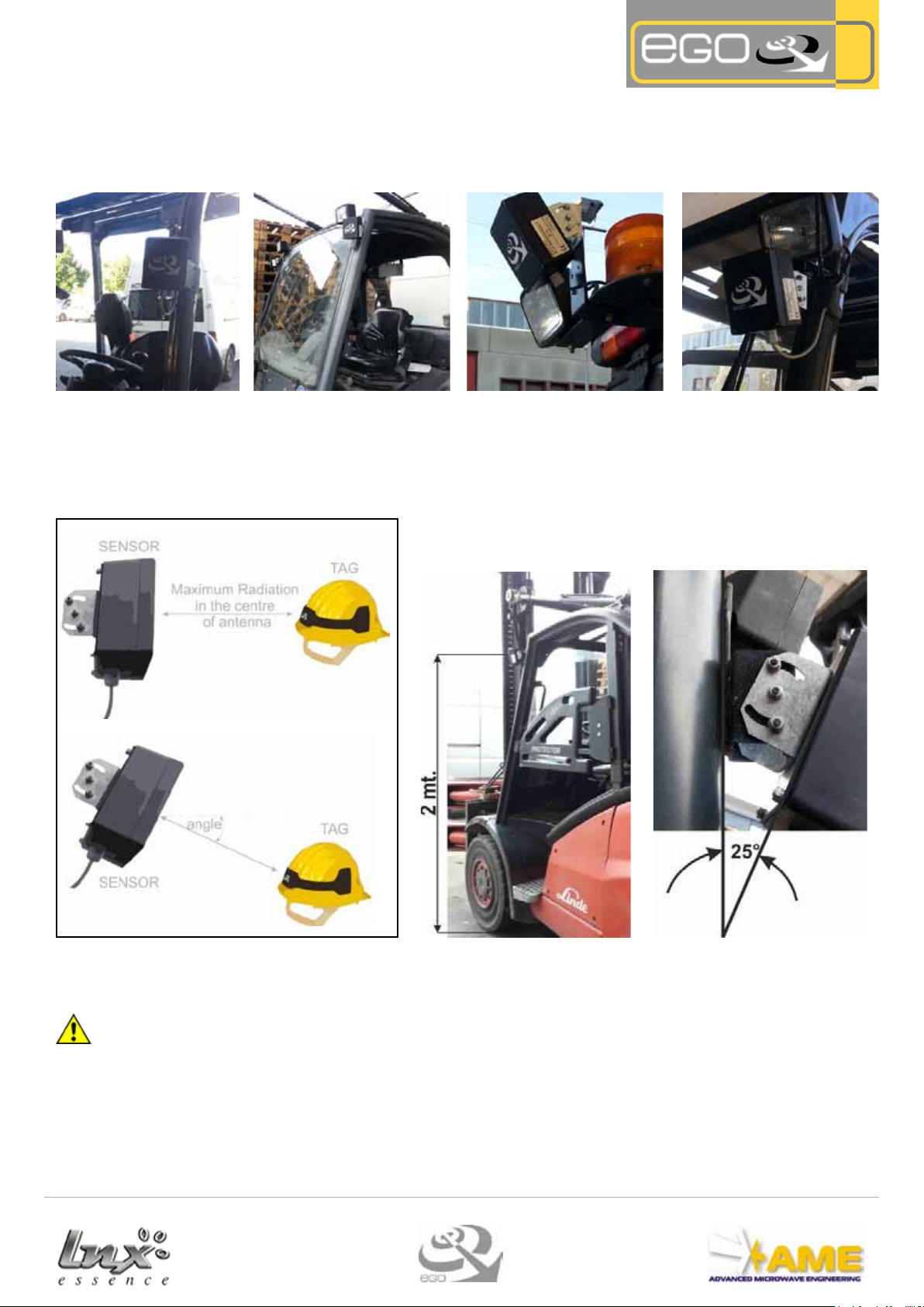
5.1.3 Positioning the sensors
When positioning the sensor, it is essential that there aren't any obstructions between the sensor and the operator who is tted
with active PPE (with TAG), that may invalidate the performances.
Illustrative examples:
Fig. 18 - Illustrative examples -
5.1.4 Sensor Direction
The satellite antenna is positioned vertically, with the cable gland outlet facing downwards and inclined towards the required coverage area.
The standard installation of the EGOpro Safety MOVE system requires
positioning the Sensors 2m high with a downward gradient of about 25°.
pro
Fig. 19 - Sensor direction -
To comply with FCC RF exposure requirements a separation distance of at least 20 cm must be maintained between the
antenna of this device and all nearby persons. This device must not be co-located or operating in conjunction with any
other antenna or transmitter except as described in this user manual.
Fig. 20 - Standard position -
Page 12

12
5.2 CPU
The CPU is the core of the system and is positioned inside the driver's cab
depending on the driver's visibility requirements.
The driver should be able to carry out all routine functions without aecting operability.
Fig. 21 - CPU -
5.2.1 CPU tting
The CPU is equipped with a clamp set up to be connected, as per the Sensors, to the supplied mechanical joint.
pro
There are mainly two installation stages of the CPU and they must be carried out in this order:
1_ MECHANICAL FITTING: Create an anchoring clamp inside the driver's
cab where the joint can be attached
17.5mm apart).
2_ ATTACHMENT: Attach the CPU already fitted with the plate to the joint
anchored on the clamp in the driver's cab.
Fig. 23 - Installation examples -
(3 holes (Ø4mm) 4mm in diameter,
5.2.2 CPU Positioning
The CPU should be placed inside the driver's cab in a position which is visible to the driver, but does not hinder operativity.
Fig. 23 - Installation examples -
Page 13

13
5.3 Splitter
Fig. 24 - Splitter -
5.3.1 Splitter Positioning
The splitter can be placed anywhere inside or outside the driver's cab even in a concealed area. The splitter's position is not important, it is essential that it doesn't obstruct the driver's and the vehicle's operability and that it works to connect the sensors and
the CPU.
pro
Fig. 25 - Installation examples -
Page 14

6. Electrical connections
There are two types of connections required, power supply and data bus, according to the diagram shown below:
Electrical connections
pro
Fig. 30 - Electrical connections -
6.1 Power supply
The entire system is powered by the CPU. A direct current (DC) power supply is required for the EGOpro Safety Move system and a
power range between 12 and 24V is required. The expected absorption is about 20W per CPU and 6W per each Sensor. The system
shall be supplied by a source with limited power
Fig. 31 - CPU Board -
LEGEND VALUE DESCRIPTION
V+ +VDC Continuos (12/24VDC) Continuos Power Supply
V- GND Ground
V_Q +VDC Switched (12/24VDC) Switched Power Supply
C1 +VDC Switched (12/24VDC) Switched Power Supply
14
Page 15
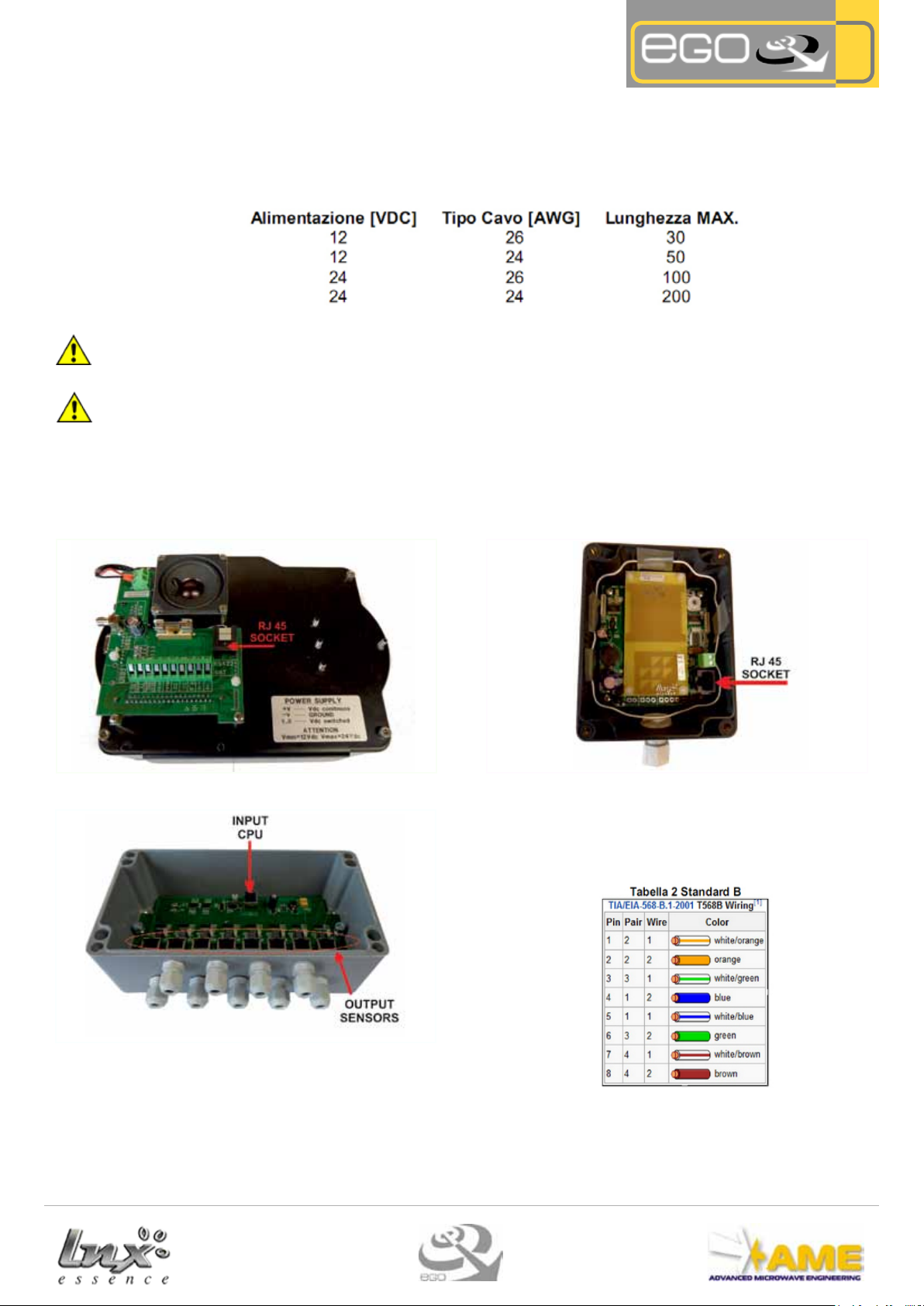
6.2 Data Bus
The connection between the Central Unit (CPU) and all other devices (Splitters and Sensors) occurs via a single dened "Data Bus"
cable. The Data Bus is conducted via a Cat.5E or above UTP type cable. The maximum connection length between Sensors, Splitters and CPUs depends on the type of cable used and type of power available, 12 or 24 VDC.
The following table advises on maximum connection lengths:
Note: the maximum connection length is understood to be between device and device (point-to-point) and not the overall length.
A Wurth Elektronik 74271132S ferrite or equivalent, must be placed on each section of the UTP cable.
Furthermore, when used under FCC regulation, a Fair Rite 0431164181 or Wurth Elektronik 74271222 or equivalent ferrite, with two cable turns, must be placed on both cables connected to the CPU, close to the CPU
We recommend to keep electrically isolated the CPU metal rear panel.
6.2.1 RJ45 Terminations
The standard version requires that the Data Bus terminations are of the type RJ45. CPUs, Sensors and Splitters have the RJ45 connector to connect to the data bus.
pro
Fig. 32 - RJ45 connection on the CPU
Fig. 34 - Connections on the Splitter -
Fig. 33 - RJ45 connection on the Sensor-
Crimp the UTP cable adhering to the same colour sequence on
each cable termination. It is advisable to crimp the cable ac-
cording to a known standard (for e.g. LAN-B) in order to avoid
making mistakes.
15
Page 16

6.3 Relay
The relay located at the back of the board, isn't externally visible, and
the connections are shown on the main connector.
Fig. 34 - Connections on the Splitter -
Fig. 34 - Connections on the Splitter -
6.3.4 Relay operating mode
There are 4 relay operating modes associated to the events detected by the CPU:
1. Deactivated relay. The relay status is not associated to any event detected by the CPU (relay is always deactivated)
2. Sound activation for the presence of Tags. The relay is activated each time the CPU loudspeaker emits a signal associated to the
presence of a new TAG on the system.
pro
Note: this mode is usually used to remotely control a loudspeaker outside the vehicle.
Note: the duration (sec) of the relay contact in this mode is 1 sec for every associated event.
3. Tag Activation + Sensor Error.The relay as well as being activated due to the presence of a new Tag will activate every time
a malfunction of an installed sensor is veried.
Note: the duration (sec) of the relay contact in this mode is 1 sec for every associated event.
4. Presence of Tag Video Alarm. The relay remains active as long as the system detects one or more transponders.
Note: The required default operational mode is the number 4
16
Page 17
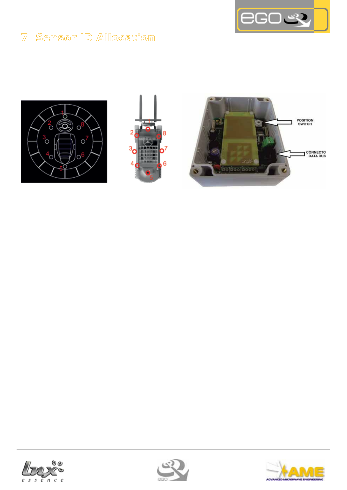
7. Sensor ID Allocation
Once the mechanical and electrical installation stage is completed, the allocation of identication to each sensor tted on the vehicle is required.
The EGOproSafety MOVE system agreement requires that the sensor position on the vehicle corresponds to a number identication,
a number between 1 and 8 according to the following diagram:
pro
Fig. 42 - Sensor ID -
To allocate an ID to the sensor, in terms of recognising the sensor on the system, the rotary-code (Position Switch), which is located
at the top right, is required to be placed on the desired number.
Note: the sensor memorises its own ID when switched on.
The tests and system validation should be conducted in open-space.
This means that obstructions should not be present in a range of at least 50m around the vehicle.
Performances may vary based on vehicle type and therefore on potential practical installation solutions
Follow the software manual instructions for conguration, testing and calibration.
17
Page 18
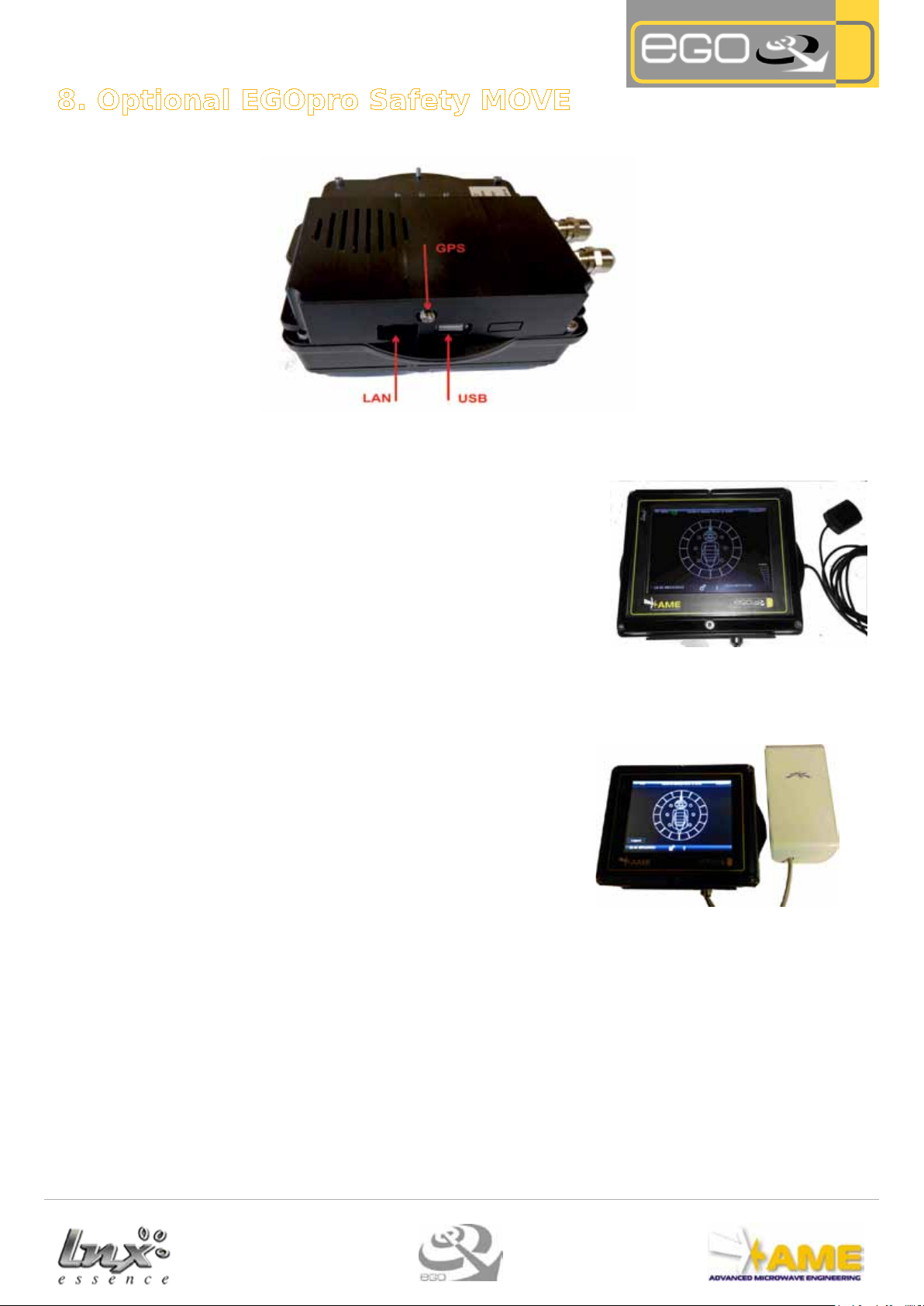
8. Optional EGOpro Safety MOVE
8.1 GPS
The PLUS version of the EGOpro Safety Move system incorporates a GPS device on-board. GPS is used in the Tracking Adaptive Range functions (tracking vehicle movements and adjusting the activation range in relation to the
vehicle's speed).
pro
Connecting the external antenna to the CPU via the connector on the right
side is required in order to receive the GPS signal. The external antenna
has a cable that is approximately 3m in length. Once connected to the CPU
place the antenna, with its magnetic stand, in an area which will enable
satellite reception.
8.2 Wi-Fi Transfer
Setting a Wi-Fi interface on the Move system is required. Wi-Fi connectivity enables the transfer of data stored on-board from the CPU onto the FTP
server.
Note: Power to the antenna occurs via POE (Power over Ethernet) directly
from the CPU. Power specication for the Wi-Fi antenna is not required.
(Supplied)
It is necessary to congure the FTP server parameters to enable data
transfer to ground level.
FTP Conguration example
[ftp]
enable = 1
ftp = www.ameol.it
username = testame
password = testame2013
Fig. 43 - GPS -
Fig. 44 - wi- -
18
Page 19

8.3 Vehicle/vehicle Anticollision
Devices called (Vehicle-Vehicle P LX 2700RIF) Reectors are required to be installed on the
vehicle in order to implement anticollision functions between vehicles.
Note: this device is integrated on the EGOpro Safety MOVE system: a Man-Vehicle anticolli-
sion system. The number of reectors that should be installed is the same as the (P LX SAT
MOVETOUCH) Sensors that are on the vehicle and used to detect employees at ground level.
The Reectors only need power and data transfer to the central unit (CPU) occurs via a wireless connection between Reectors and Sensors.
pro
8.3.1 Reector power supply
Power the device via the appropriate J4 screw connector; it is possible to supply power using both DC and AC with a 12/24V voltage value.
The device is required to be connected to a sub-distribution panel supply.
NOTE: It is not important to abide by the polarity on the terminals.
Vehicle-Vehicle 2700RIF Electrical connections
NOTE: the Vehicle-Vehicle P LX 2700RIF version does not require the use of these two outlets.
8.3.2 Positioning and installation of the Reectors
The Reectors have the same dimensions as the Sensors.
The positioning of the reectors follows the sensors diagram to which they are
associated (front, rear or lateral).
Reectors and Sensors should be positioned at dierent heights in order to
minimise the "electromagnetic visibility" between the two devices.
Usually the reectors are positioned on the roof of the vehicle whereas the
sensors are placed lower down.
The reectors should be positioned so that they are facing outwards in the
direction of the detection required. The joints supplied to facilitate this type of
installation can be used.
Fig. 44 - Reector -
Fig. 46 - Reector Positioning Examples -
19
Fig. 45 - Reector Positioning -
Page 20

8.4 Hangar Mode
The Hangar mode enables the power level of the sensors to be dynamically
modied, for Vehicle-Vehicle detection and when the vehicle is not in conditions of direct visibility (No Open Space), in order to compensate the electromagnetic attenuation due to the presence of obstructions.
The system is capable of "understanding" when the vehicle is not in conditions of visibility due to the use of two proximity sensors placed on the sides
of the vehicle.
The proximity sensors detect the presence of an obstruction at about 80cm
and the status information "Vehicle not in condition of visibility" is transmitted to the CPU via wireless interface.
Fig. 47 - Hangar -
8.4.1 Fitting the proximity Sensors
The proximity sensors should be tted on the sides of the vehicle in a location guarded from any bumps as such to allow obstructions to be detected.
pro
Fig. 48 - Examples of proximity sensors -
The wireless interface sends the "obstructions present" status to the Move system's Sensors that are on the vehicle.
Fig. 49 - Obstruction present -
20
Page 21

The wireless interface is housed in a box of 115x90x55 (mm) dimensions. It can be placed inside the vehicle in an unscreened area.
The two proximity sensors are supplied with a 10m stub cable (SAC-5P-10,0-PUR/M12FS) in order to connect to the wireless interface.
Follow the legend on the wireless interface container and use the diagram shown below for the connection between the proximity
sensors and wireless interface.
Note: the standard power supply required for this device is 12 VDC. A 24 VDC power supply can be applied.
Interface to sensors connection
pro
Fig. 50 - Interface to sensors connection
9. Speed measurement module
The speed measurement radar module, allows to detect the speed even in the absence of the GPS signal . The module must be
installed at an angle 45 degrees from the ground to a height of between 30 and 50 cm from the ground . The direction of the assembly is in reference to the fairlead position , as shown in the drawing.
The speed sensor is supplied with 5m UTP cable and must be connected in a manner similar to the sensors, via an RJ45 connector,
to be crimped to the cable end, which must be connected to the splitter for EGOproSafety MOVE or CPU for EGOproSafety MOVE
MINI. The wiring diagram must follow the standard TIA / EIA-568-B as shown in the following table.
21
Page 22

10. Active PPE provision
Every operator who works in areas where there are moving vehicles installed with the safety aid EGOpro Safety Move system, must
wear the active PPE in order to be detected by the system.
10.1 Active harness
The harnesses need to be set up by inserting the provided TAGs in the appropriate pockets.
1 Tag in the rear pocket and 1 Tag in the front pocket.
pro
10.2 Active helmet
The adhesive protection needs to be removed and secure the Tag as shown in the diagram in order to set up the active helmet.
Before securing the Tag to the helmet it is NECESSARY to clean the helmet with the appropriate cloth provided with
the Tag
23
Page 23

11. Statements
The EGOPro Safety MOVE system (the Product) constitutes a safety aid instrument to prevent man-vehicle and vehicle-vehicle collisions in working areas. It does not constitute a personal safety system as it does not interact in any way with the machines on
which it is installed (for example, applying the brakes etc.)
Inherently, the EGOPro Safety MOVE system's eectiveness is subordinate to the operator's action whenever and wherever, and in
any case it does not exonerate the Buyer and the operator from adopting routine safety procedures required for any specic oper-
ating situation (organising the construction site, training operators on safety, designing signs, necessary cautions etc.) and from
observing due diligence regulations.
Furthermore the Safety Move system, cannot guarantee the connection to radio frequency and therefore detection taking place in
any case, given that this connection cannot occur properly because of electromagnetic interferences or due to other causes such
as the lack of power of one or more devices, for example.
A.M.E. will not be held liable in any way for any direct or indirect damages, of any kind (including personal injury or property damage) subject to any matter whatsoever experienced by the Buyer or third parties as a result of using the Product.
EGOpro Safety Move Mini is a Radio frequency system for detection of people and things in particular areas and is in conformity with
the essential requirements and other relevant requirements of the following directives:
• R&TTE DIRECTIVE (1999/5/EC)
• EMC directive (2014/30/CE)
R&TTE: Health and Safety (Art. 3(1)(a)): EN 60950-1:2006 + A1:2010 + A11:2009 + A12:2011; EN62311:2008
R&TTE: EMC (Art. 3(1)(b)) EN 301 489-1 v1.9.2, EN 301 489-3 V1.6.1
R&TTE : SPECTRUM (Art. 3(2)): EN 300 220-2 V2.4.1, EN300 440-2 V1.4.1
EMC: Industrial Trucks: EN12895 (2000)
pro
Warning: This device complies with part 15 of the FCC Rules. Operation is subject to the following two conditions: (1) This device
may not cause harmful interference, and (2) this device must accept any interference received, including interference that may
cause undesired operation.
Changes or modications not expressly approved by the party responsible for compliance could void the user’s authority to operate
the equipment.
12. DATA SHEET
CAUTION. Risck of explosion if battery is replaced by
an incorrect type. Dispose of used batteries according
INFORMATION FOR USERS
If at any time in the future you should need to disponse of this product (equipment and batteries), please note that
waste electrical products should not be sisposed with household waste. Please recycle where facilities exist.
24
Page 24

Advanced Microwave Engineering
Via Lucca 50-54 - Firenze
info@ameol.it
www.ameol.it
Tel. +39 055 73921
Fax +39 055 7392141
Manuale EGOpro Safety Move HW EN v03_16
www.ameol.it
 Loading...