

Page 1

For review by:
Issue No. Date
Description of Revision Rev. Date Prepared: A. Piccioli
1.3 12/04/07
5 2706/07
Approved:
User Manual Updated as of
27 giu. 07 – Rel.1.3.5 Page 1 of 70
Page 2

NOTES:
This apparatus and its documentation must be thoroughly reviewed, to
become familiar with safety instructions before starting operating
procedures.
To assure a correct and safe utilisation, the user of this apparatus shall
observe all information and warnings contained herein.
The Apparatus must be connected to an electrical system that complies
with current national standards.
The information contained herein is subjected to change without
advance notice.
This device complies with Part 15 of the FCC Rules. Operation is
subject to the following two conditions:
(1) this device may not cause harmful interference, and
(2) this device must accept any interference received, including
interference that may cause undesired operation.
Changes or modifications not expressly approved by the party
responsible for compliance could void the user's authority to operate the
equipment.
User Manual Updated as of
27 giu. 07 – Rel.1.3.5 Page 2 of 70
Page 3

TABLE OF WRITTEN CONTENTS
1. SECURITY INSTRUCTIONS AND CONSIDERATIONS.............................. 1-5
2. ABBREVIATIONS ................................................................................... 2-5
3. GENERAL INFORMATION ...................................................................... 3-6
3.1. OPERATING PRINCIPLE OF THE LNX SYSTEM 3-6
STANDARD, FAST and APB Mode .......................................................................... 3-7
TRACK Mode ........................................................................................................... 3-8
ECM Mode ............................................................................................................... 3-9
BEEPER FAST Mode ............................................................................................. 3-10
3.2. E
4. TECHNICAL DESCRIPTION OF THE DEVICES..................................... 4-13
XAMPLES OF APPLICATIONS OF THE LNX SYSTEM 3-11
4.1. I
LLUMINATOR UKOPLX2101FHU 4-13
Mechanical Characteristics ................................................................................... 4-13
Mechanical Characteristics ................................................................................... 4-14
Wiring for UKOPLX2101FHU ................................................................................ 4-14
POSITION OF LABEL................................................................................................... 4-14
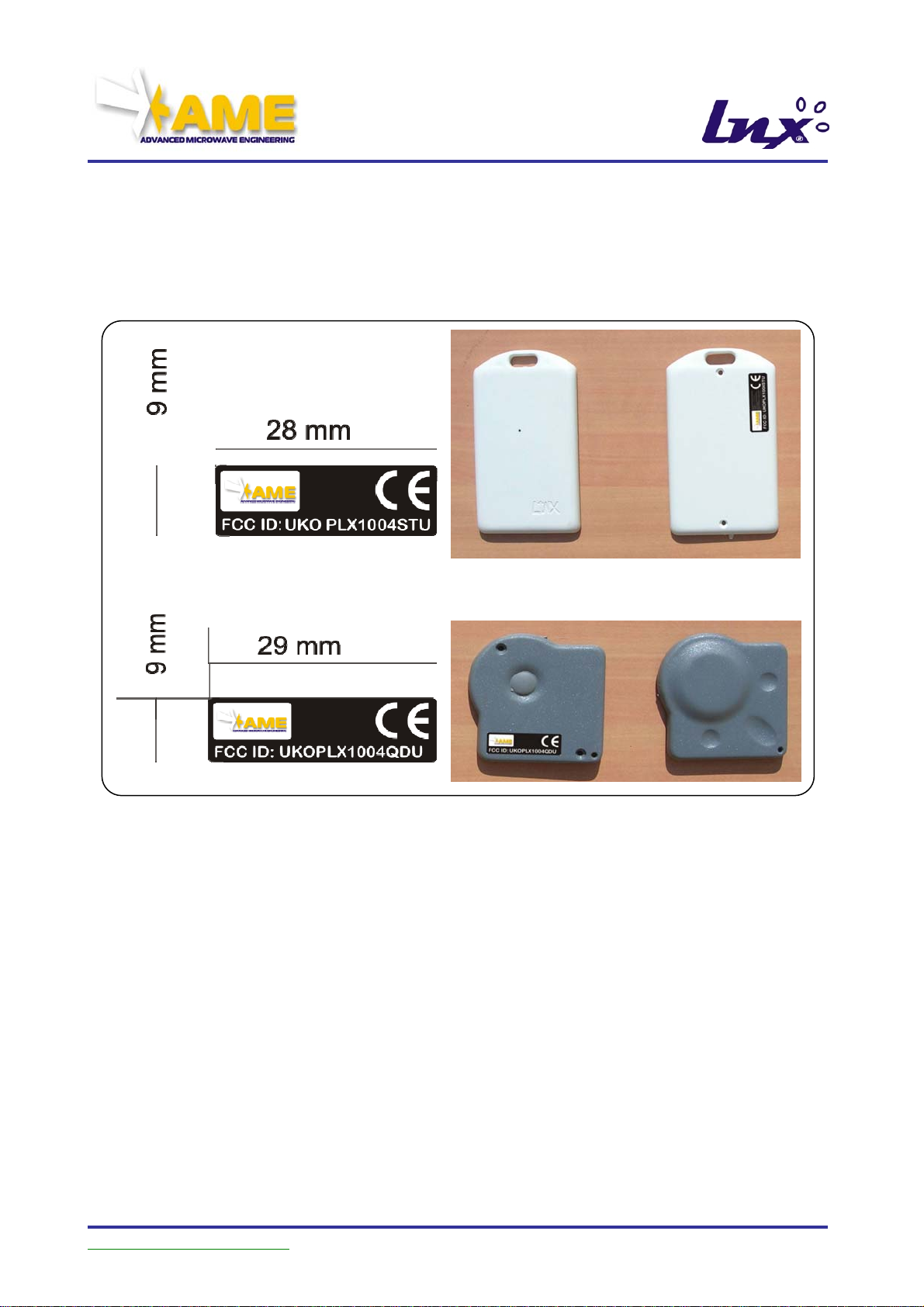
4.2. TAG DUALFREQUENCY UKOPLX1004STU & UKOPLX1004QDU 4-15
Mechanical Characteristics ................................................................................... 4-15
Wiring for UKOPLX1004STU or UKOPLX1004QDU............................................... 4-16
POSITION OF LABEL................................................................................................... 4-16
4.3. UKOPLX2002 RADIO RECEIVER 4-17
Mechanical Characteristics ................................................................................... 4-17
Wiring for UKOPLX2002........................................................................................ 4-17
POSITION OF LABEL................................................................................................... 4-18
5. INSTALLATION .................................................................................... 5-19
5.1. I
5.2. P
NTRODUCTION 5-19
Illuminator UKOPLX2101FHU............................................................................... 5-19
Receiver UKOPLX2002.......................................................................................... 5-19
Transponder UKOPLX1004STU or UKOPLX1004QDU.......................................... 5-19
RECAUTIONS 5-20
Initial Inspection.................................................................................................... 5-20
Packing and Unpacking ........................................................................................ 5-20
Preparation for Use ............................................................................................... 5-20
Caution.................................................................................................................. 5-20
Connection to Power Supply Mains....................................................................... 5-21
5.3. TECHNICAL CHARACTERISTICS OF THE MATERIALS EMPLOYED 5-21
Power supply cord................................................................................................. 5-21
Data cables ........................................................................................................... 5-21
Auxiliary cables .................................................................................................... 5-22
Environmental conditions...................................................................................... 5-22
Cleaning the instrument........................................................................................ 5-22
Caution.................................................................................................................. 5-22
5.4. N
Installation ............................................................................................................ 5-22
Equipment required for installation....................................................................... 5-22
Notes on installation ............................................................................................. 5-23
OTES ON INSTALLATION 5-22
User Manual Updated as of
27 giu. 07 – Rel.1.3.5 Page 3 of 70
Page 4

Caution.................................................................................................................. 5-23
5.5. INSTALLATION OF THE APPARATUS 5-24
5.6. STARTING THE APPARATUSES 5-27
5.7. CONFIGURATION OF ILLUMINATOR UKOPLX2101FHU 5-28
5.8. CONFIGURATION OF TRASPONDER UKOPLX1004STU / UKOPLX1004QDU 540
5.9. CONFIGURATION OF RECEIVER UKOPLX2002 5-44
Supplementary power supply ............................................................................... 5-44
External interface.................................................................................................. 5-45
Operating mode..................................................................................................... 5-48
Startup .................................................................................................................. 5-48
LEDs...................................................................................................................... 5-48
Button functions .................................................................................................... 5-48
STAND ALONE MODE ........................................................................................... 5-49
ASCII Stand Alone data format............................................................................. 5-49
Programming ......................................................................................................... 5-51
NETWORKING ....................................................................................................... 5-54
Binary communication protocol ............................................................................. 5-54
6. ELECTRICAL AND MECHANICAL SPECIFICATIONS............................. 6-64
6.1. ACTIVATOR UKOPLX2101FHU 6-64
Mechanical characteristics.................................................................................... 6-64
External interface.................................................................................................. 6-64
Electrical characteristics ....................................................................................... 6-64
Environmental specifications ................................................................................ 6-64
Radio unit specifications ....................................................................................... 6-64
Antenna specifications: AME ANT 2.44................................................................. 6-65
6.2. TRASPONDER UKOPLX1004STU & UKOPLX1004QDU 6-66
Mechanical characteristics.................................................................................... 6-66
UKOPLX1004STU.................................................................................................. 6-66
UKOPLX1004QDU................................................................................................. 6-66
Electrical characteristics ....................................................................................... 6-66
Environmental specifications ................................................................................ 6-66
Radio Frequency Specifications ............................................................................ 6-67
433 MHz. transmitter............................................................................................ 6-67
2.45 GHz receiver.................................................................................................. 6-67
6.3. R
Mechanical characteristics.................................................................................... 6-68
Electrical characteristics ....................................................................................... 6-68
Specific external interfaces ................................................................................... 6-68
Radio Frequency Specifications ............................................................................ 6-68
Environmental specifications ................................................................................ 6-68
ECEIVER UKOPLX2002 6-68
7. LAN PLX2002 CONFIGURATION (OPTIONAL FUNCTION) ..................... 7-69
8. STARTING THE APPARATUS................................................................ 8-69
9. TEST ................................................................................................... 9-69
10. PRECAUTIONS .................................................................................. 10-69
11. MAINTENANCE.................................................................................. 11-70
User Manual Updated as of
27 giu. 07 – Rel.1.3.5 Page 4 of 70
Page 5

1. SECURITY INSTRUCTIONS AND CONSIDERATIONS
This apparatus complies with the safety requirements set out by current standards. To
assure a proper and safe use of this apparatus, it is necessary thoroughly to understand
and carefully to observe the following instructions, before starting operating procedures.
If the unit is to be connected to other apparatuses or accessories, before
powering each unit ensure that there is continuity in the ground connection
between them.
For units connected permanently without protection fuses, automatic breaking
circuits or similar solutions, mains voltage must be supplied through fuses or
protections connected to the units themselves.
Every interruption or loosening of the protective conductor, inside or outside the
unit or in a connection to other units, will cause a potential electric shock hazard
which could result in personal injuries.
The protective conductor must not be interrupted intentionally.
To prevent electric shocks, do not remove protections or lids from the unit; to
service the apparatus, contact a qualified service centre.
To assure continuous protection against the risk of fire, replace the fuses on the
power supply mains only with fuses of the same type and size.
Comply with safety standards and rules, and also with the additional accident
prevention instructions specified herein.
2. ABBREVIATIONS
RFID Radio Frequency Identification
PLX1004STU Similar to UKOPLX1004STU, Identifying code for the rectangular TAG
PLX1004QDU Similar to UKOPLX1004QDU, Identifying code for the square TAG
PLX2002
PLX2101FHU Similar to UKOPLX2101FHU, Identifying code for the ILLUMINATOR
IT System IT apparatus dedicated to managing the data acquired by the system
Activtor Similar to UKOPLX2101FHU
Illuminator Similar to UKOPLX2101FHU
Receiver Similar to UKOPLX2002
ILL Similar to UKOPLX2101FHU
RIC Similar to UKOPLX2002
TAG Similar to UKOPLX1004STU or UKOPLX1004QDU
User Manual Updated as of
Similar to UKOPLX2002, Identifying code for the RECEIVER
27 giu. 07 – Rel.1.3.5 Page 5 of 70
Page 6
3. GENERAL INFORMATION
3.1. Operating Principle of the LNX System
The system proposed herein is based on the extensive use of LNX technology
apparatuses. Therefore, it is essential to provide a short note describing the specific
characteristics and potential of this technology.
The LNX system is based on the operating principle of
Radio Frequency Identification (RFID) systems with
ACTIVE transponder.
An active transponder is a self-powered electronic
device with the ability to receive data through a
transmission at 2.45GHz, process them, and make the
results available through a transmission at 433MHz.
The system as a whole is thus formed by three
elements:
• The ILLUMINATOR, tasked with generating the transmission at 2.45GHz and
produce a coverage area.
• The ACTIVE TRANSPONDER, which will be designated with the acronym TAG
(whose operation we have already described)
• The RECEIVER, tasked with receiving the data transmitted by the TAG and
transferring them in turn to the IT system above it.
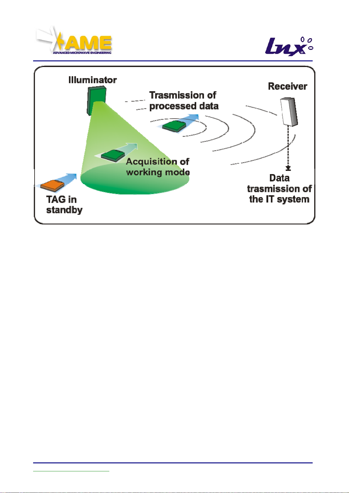
The operating principle is extremely simple: the transponder lies in a stand-by state until it
is “illuminated” by the microwave source which “awakens” it.
Only then does it “activate”, interpret the signal transmitted by the illuminator, perform the
necessary operations and transmit its code and the results obtained on the RF channel to
the receiver located within the coverage range.
User Manual Updated as of
27 giu. 07 – Rel.1.3.5 Page 6 of 70
Page 7
Moreover, since the active transponder of the LNX system is an apparatus with on-board
frequency generation and it is provided with battery as well as a chip and a transmitter, the
TAG can become a transmission device irrespective of whether it is located in the
activation area.
This allows the firmware loaded in the TAG’s memory to perform numerous processes and
to transmit the result at any time and for an infinite number of times.
This intrinsic characteristic of the LNX system enables to use the same products (receiver,
illuminator, TAG) in various applications, even very different ones.
The following is the description of the work modes currently implemented on the LNX
system.
STANDARD, FAST and APB Mode
In this mode, the TAG activates its transmission when it is illuminated by an illuminator.
A similar operation to standard mode also occurs with the FAST and APB modes
(described below); for now, suffice it to know that they are differentiated by the
transmission and waiting times.
User Manual Updated as of
27 giu. 07 – Rel.1.3.5 Page 7 of 70
Page 8
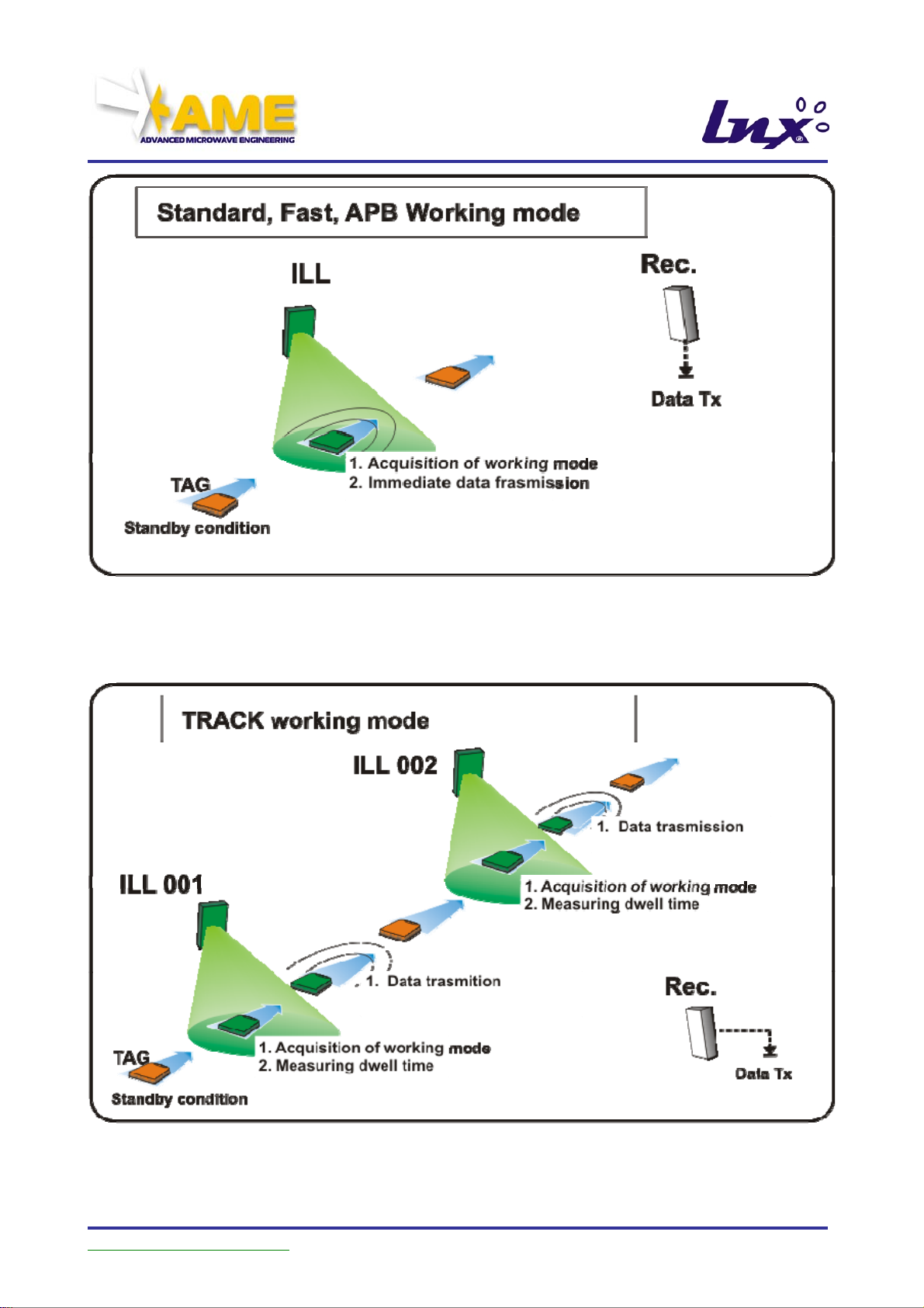
TRACK Mode
Operating mode that enables to track a TAG’s path through an area where multiple
illuminators are positioned.
From the data transmitted by the TAG it is possible to know by which illuminators the TAG
was successively illuminated and how long it remained within their operating range.
User Manual Updated as of
27 giu. 07 – Rel.1.3.5 Page 8 of 70
Page 9
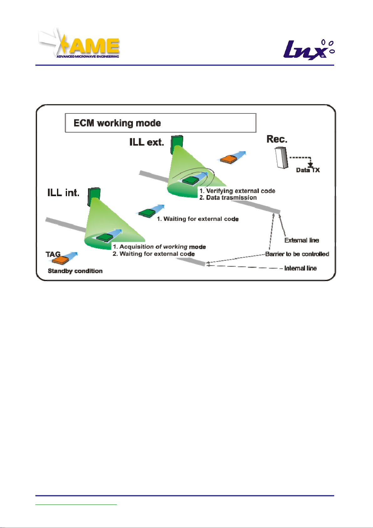
ECM Mode
Operating mode that enables to a TAG’s passage through a barrier, while also keeping
track of the direction of travel.
If the barrier is wide, the system provides for the illuminators to be so configured as to
enable the creation of barriers of up to 15m, with performance optimisation.
User Manual Updated as of
27 giu. 07 – Rel.1.3.5 Page 9 of 70
Page 10
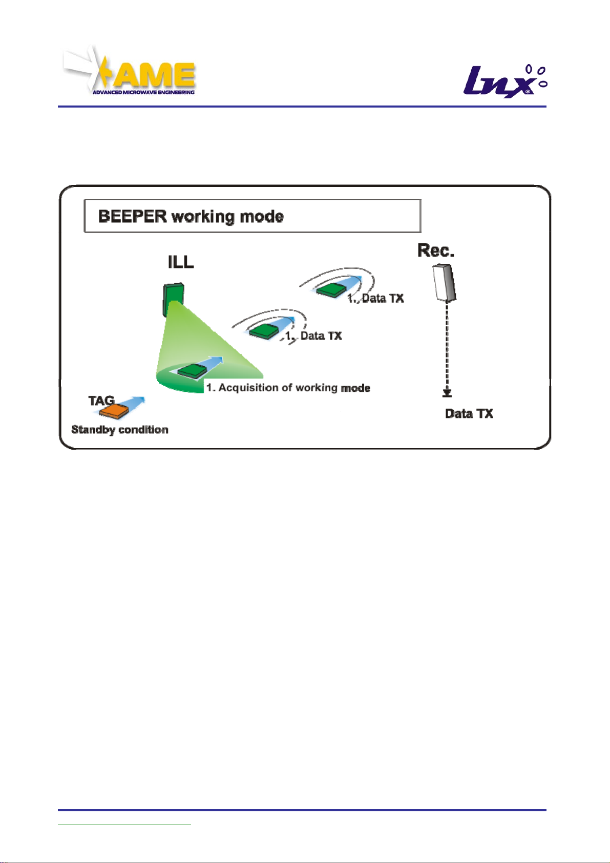
BEEPER FAST Mode
This mode enables to excite the TAG and to set it to a condition of repetitive transmission
of the same message for a defined time, even after it leaves the activation area.
Observing the configuration tables provided in the remainder of this manual, it will be
readily apparent that for this particular configuration, 32 versions are available, plus 22 of
the BEEPER FAST mode.
The difference between the BEEPER FAST mode is that with the former the TAG changes
working mode only at the end of its transmission cycle, or upon receiving the code 999I or
999E code by an illuminator. With the BEEPER FAST mode, instead, the TAG changes its
operating mode every time it is activated by an illuminator with different work settings.
User Manual Updated as of
27 giu. 07 – Rel.1.3.5 Page 10 of 70
Page 11

3.2. Examples of Applications of the LNX System
There are many applications of the LNX system in the various work modes described
above.
STANDARD Mode: example of
application for the management of
vehicle accesses.
The TAG is positioned on the vehicle,
the illuminator and the receiver are
positioned near the motorised barrier.
When the illuminator activates the
TAG, the latter transmits its code to
the receiver. The receiver processes
the data, verifies the TAG’s
authorizations and proceeds to open
the barrier.
FAST Mode: allows to use the system
described above to monitor travel times
between an illuminator and the next
one. In this mode, therefore, the system
functions as a time-measuring system.
TRACK Mode: enables to monitor the
movements of “labeled” objects or to
verify at any time their stage of
production.
User Manual Updated as of
27 giu. 07 – Rel.1.3.5 Page 11 of 70
Page 12

LNX is able to cover any activation radius of the transponder, up to about 12 meters; in
turn, the transponder is able to communicate efficiently up to about 60 meters in a free
area.
The LNX technology allows to produce even highly complex systems at low costs, allowing
to automate both industrial and private facilities.
Today, the LNX system is the most modern, effective and economical solution of handsfree short-range automatic identification and data exchange indoors and outdoors (Italian
patent FI2000A000221 of November 6, 2000, and European Patent (pending) no.
EP1209615)
• ability to modulate activation ranges (up to 12 m)
• large code communication coverage areas (up to 60 m)
• multi-receiver operation
• very low consumption for long transponder operating times
• precise spatial definition of the activation area
User Manual Updated as of
27 giu. 07 – Rel.1.3.5 Page 12 of 70
Page 13
A
A
A
4. TECHNICAL DESCRIPTION OF THE DEVICES
The following is the description of the components of the LNX system:
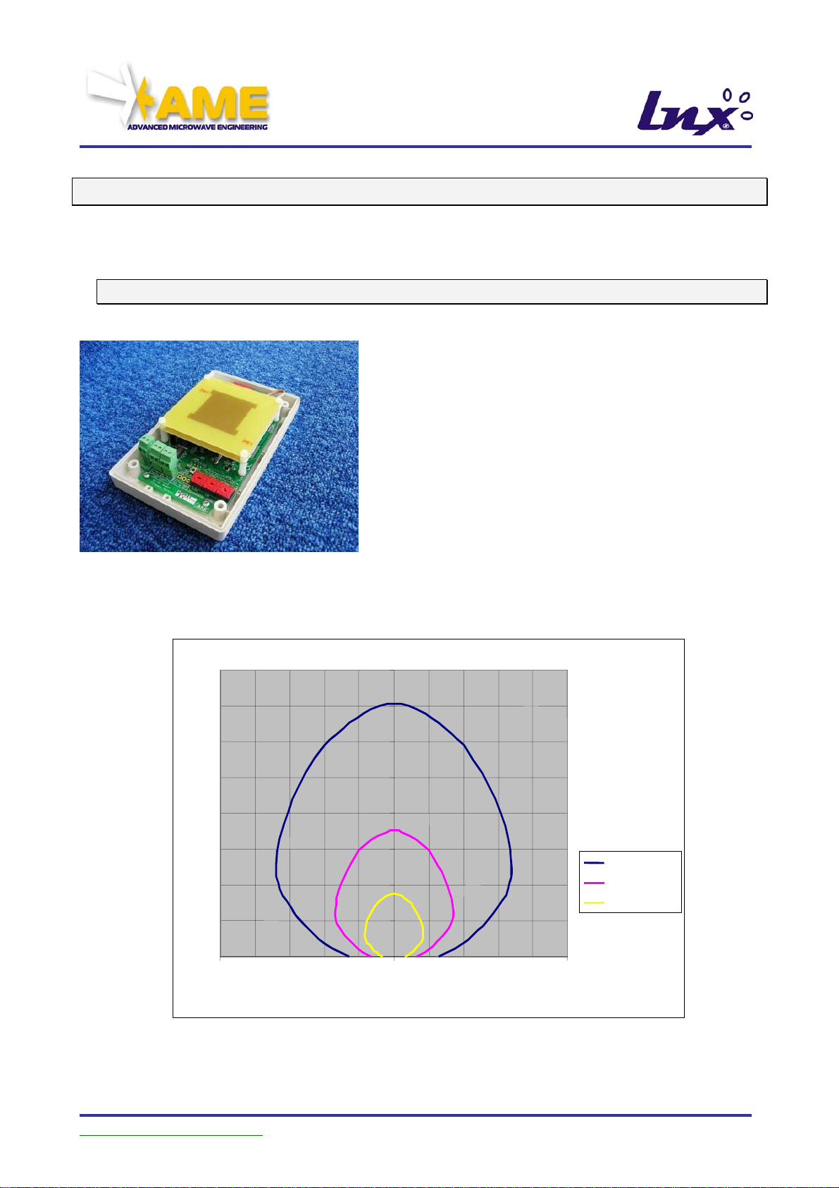
4.1. Illuminator UKOPLX2101FHU
CODED ILLUMINATOR LX2101 generates an
encoded signal at 2.45GHz to activate the LX1004
Dual Frequency Tag.
The device needs only the 12/24V direct (Vdc) or
alternating (Vac) power supply; once it is powered, it
will start continuously transmitting its own code.
In compliance with the ETSI EN 300-440 standard,
it transmits with power levels below +20 dBm (100
mW), which cannot be incremented.
The influence lobe with circular conical shape
which emits microwaves has an overall opening of
about 90° - 100°, within which are activate the
LX1004 transponders.
A representation of the antenna radiation lobe at 2.45GHz is provided below
16
14
12
10
m
8
6
4
2
0
-10 0 10
m
Linx
Illuminator
Coverage
AME ANT 2. 4 4
tt (dB)= 0
tt (dB)= 6
tt (dB)= 12
User Manual Updated as of
27 giu. 07 – Rel.1.3.5 Page 13 of 70
Page 14
[1]
pply
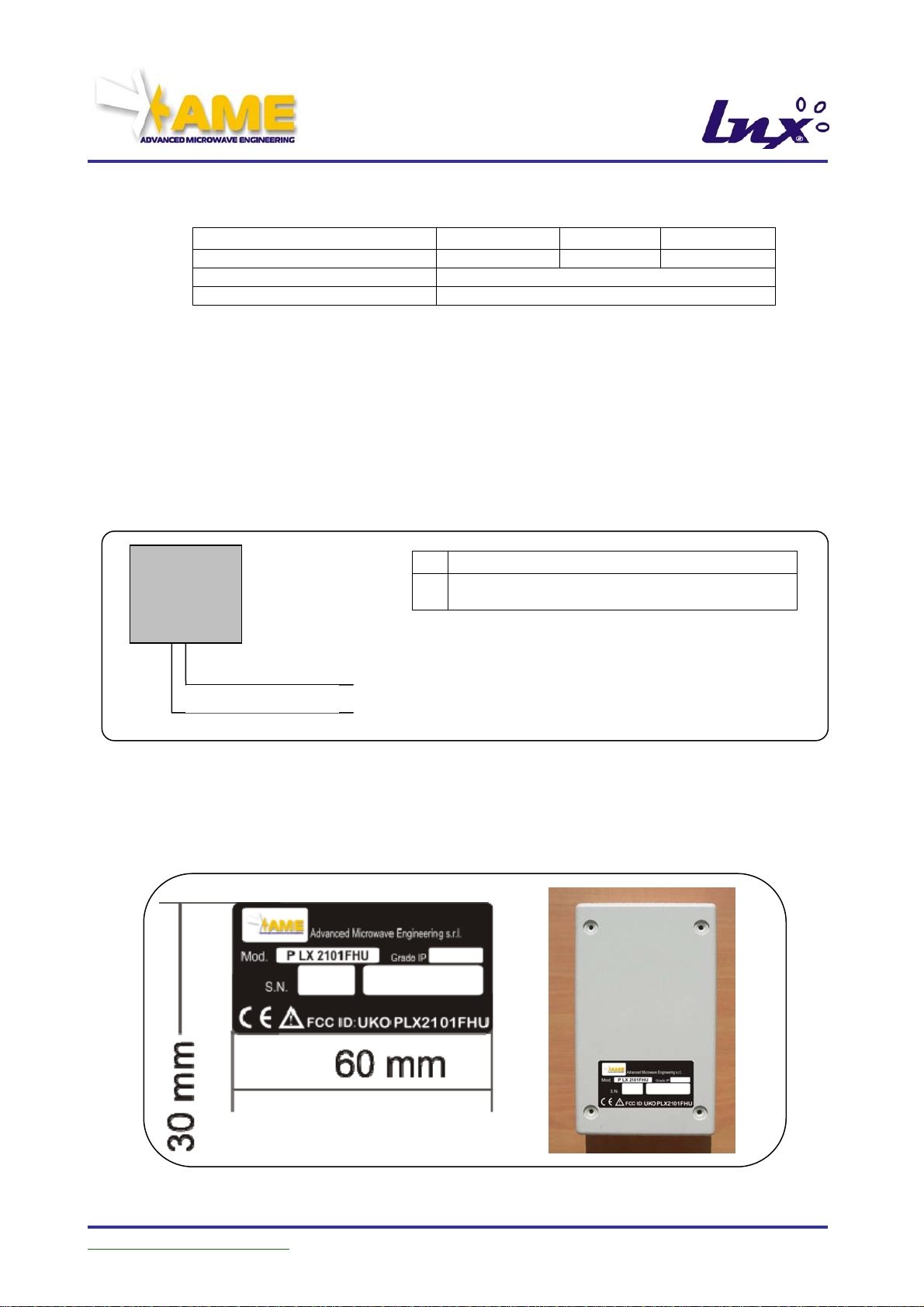
Mechanical Characteristics
Parameter
External dimensions (L x H x P)
Colour
Degree of protection
158 mm 95 mm 45 mm
Ivory RAL 9002
IP56
Wiring for UKOPLX2101FHU
The wiring provides the following connections:
• Power Supply [1]: (12/24V ac, dc) with maximum utilisation power 20W
• RS422 [2]: connection on serial line RS422, to be activated to
communicate with other illuminators installed and generate a
synchronism in the transmission.
Illuminator
LX 2101
Power su
[2] Line RS422
Figure 1: LNX Illuminator Wiring
OSITION OF LABEL
P
Power supply PCV, 2 wires x 0.75mm
1
Line RS422 suitable cable for
2
RS422 line
User Manual Updated as of
27 giu. 07 – Rel.1.3.5 Page 14 of 70
Page 15
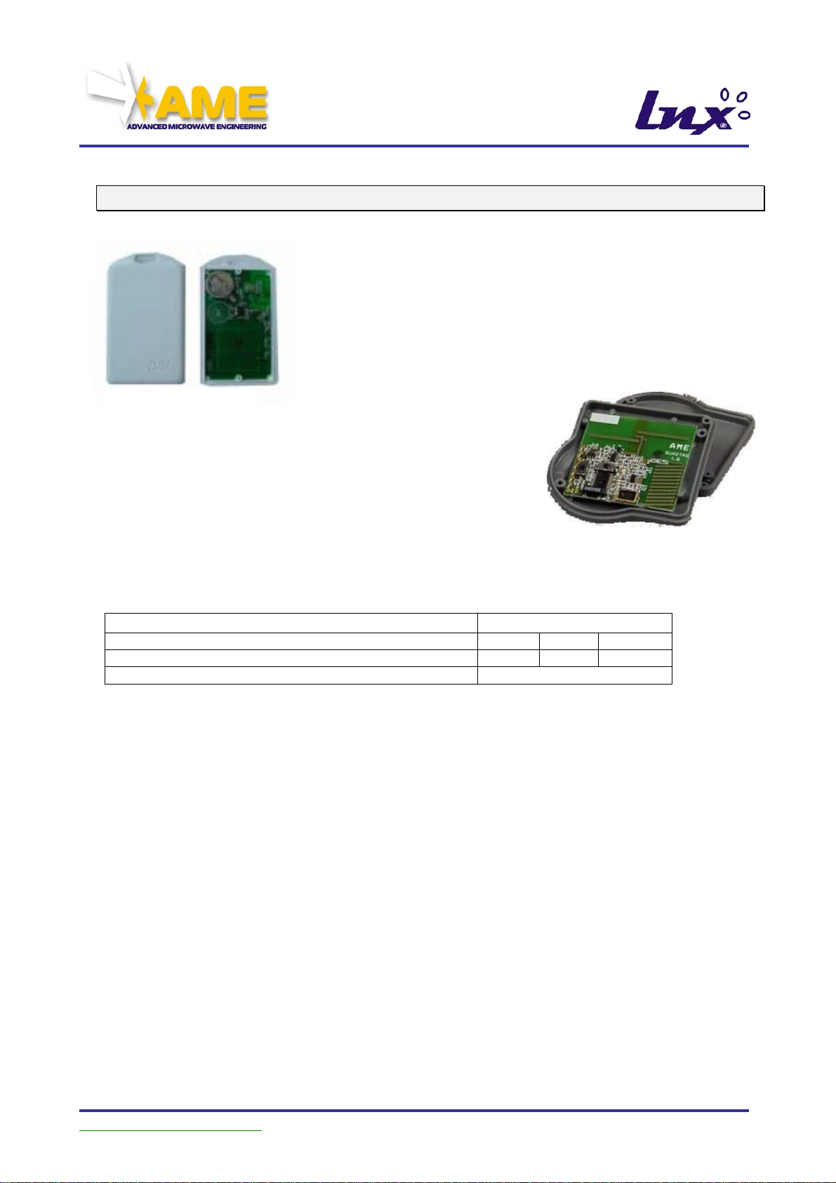
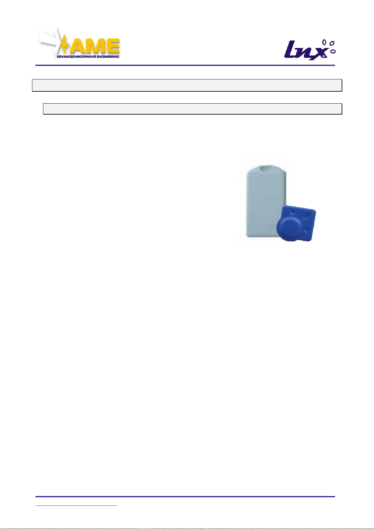
4.2. TAG DualFrequency UKOPLX1004STU & UKOPLX1004QDU
Normally off, it activates in the area of influence of the
PLX2101FHU illuminator. In reply, it transmits its own code
preceded by the code of the illuminator in whose area the
TAG was activated, at a reply frequency of 433MHz.
Equipped with replaceable lithium battery, it has an
endurance of over 100,000 transmissions.
The activation range at 2.45 GHz under the PLX2101FHU
illuminator is about 12 meters in free area; the transmission
at 433 MHz to the receiver PLX2002, compliant with ETSI
EN 300-220, can vary between 40 meters and 60 meters in
free area.
Mechanical Characteristics
Parameter
External dimensions UKOPLX1004STU (L x H x P)
External dimensions UKOPLX1004QDU (L x H x P)
Colour
95 mm 56 mm 9 mm
52 mm 52 mm 9 mm
White
User Manual Updated as of
27 giu. 07 – Rel.1.3.5 Page 15 of 70
Page 16
Wiring for UKOPLX1004STU or UKOPLX1004QDU
The system is self-powered and requires no wiring.
POSITION OF LABEL
User Manual Updated as of
27 giu. 07 – Rel.1.3.5 Page 16 of 70
Page 17
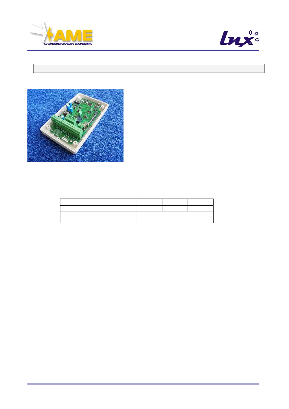
4.3. UKOPLX2002 Radio Receiver
Radio Receiver (433 MHz) for Dual Frequency TAG
The device, powered with direct (Vdc) or alternating
(Vac) 12/24 V voltage, interfaces to the external
devices through its communications interfaces,
which are a relay and the standard serial
communication channels (RS232, RS422 ethernet,
wiegand, magstripe). In compliance with ETSI EN
300-220, in this configuration the reception range of
the PLX1004STU or PLX1004QDU TAGs can vary
between 40 and 60 meters in free area.
The receiver provides for filtering the data receive
according to the code of the PLX2101FHU illuminator that activated the transponder.
Mechanical Characteristics
Parameter
External dimensions (L x H x P)
Colour
Degree of protection
158 mm 95 mm 45 mm
Ivory RAL 9002
IP56
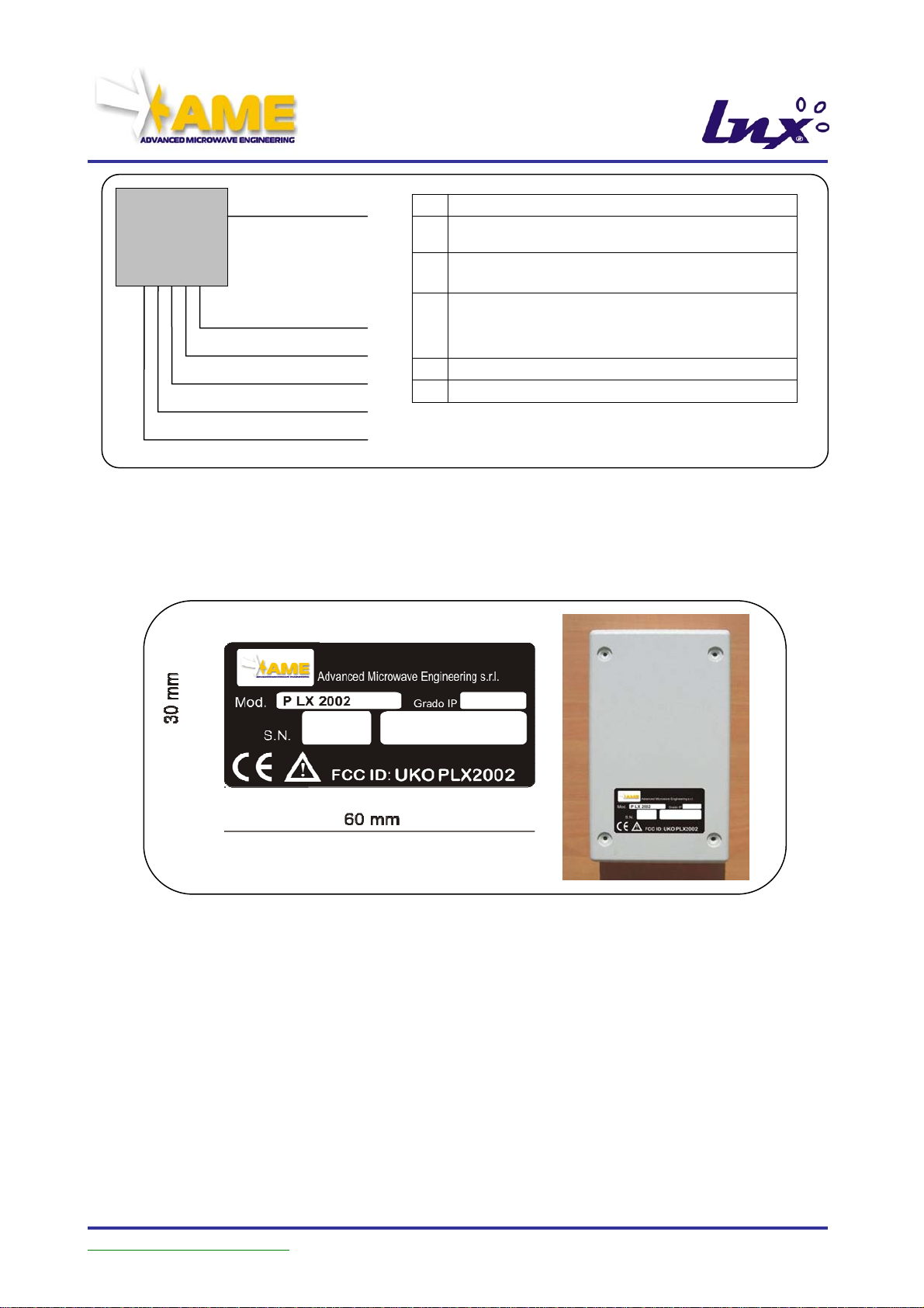
Wiring for UKOPLX2002
The wiring provides the following connections:
• Power Supply [1]: (12/24V ac, dc) with maximum utilisation power 20W
• RS232 [2]: connection on serial line RS232, always active
• RS422 [3]: connection on serial line RS422, to be activated
• Magstripe [4]: Magstripe ISO 7811 TRACK 2 connection (standard used by
access control peripherals), to be activated
• Wiegand [5]: Wiegand connection, 37BIT protocol (standard used by access
control peripherals), to be activated
• TCP/IP [6]: connection to the LAN (NEEDS ADDITIONAL ELECTRONICS;
the relevant documentation is not included in the present
manual), to be activated
• Service [7]: Relay output, to be activated.
• Tag Present [8]: signals the reception of data from a TAG
• Aux Pwr Sup [9]: (5V dc stabilised) auxiliary power supply line
User Manual Updated as of
27 giu. 07 – Rel.1.3.5 Page 17 of 70
Page 18
PLX2002
Receiver
[3] or [4] or [5] or [6] Data Line
[8] Tag present Line
[9] AUX Pwr Supply
Figure 2: LNX Receiver Wiring
[7] Serv.
[1] Pwr Sup.
[2] RS232 Line
POSITION OF LABEL
Power supply PCV, 2 wires x 0.75mm
1
Auxiliary power supply
9
PCV, 2 wires x 0.75mm
RS232 Line suitable cable for
2
RS232 line
3
Data Cat. 5 UTP 8 wires
..
6
Tag present Line PCV, 2 wires x 0.50mm
7
Relay Line PCV, 2 wires x 0.50mm
5
User Manual Updated as of
27 giu. 07 – Rel.1.3.5 Page 18 of 70
Page 19

5. INSTALLATION
5.1. Introduction
Certain specific functional characteristics are required for the identification system:
Illuminator UKOPLX2101FHU
9 It should be installed according to the following procedures:
o position it above the centre of the lane to be illuminated, not exceeding 4
metres; otherwise, it may be positioned laterally as shown in the following
figure. In this second case, it should be positioned at a height of 2.20
metres to 3.00 metres, orienting it towards the area to be covered by the
activation lobe; for the installation, the dedicated bracket can be purchased
and used.
o it must be positioned in such a way that there are no obstacles of any kind
between the device and the area to be covered by the activation lobe.
o the devices that will be used will transmit their identifying code which will be
received by the transponder; the code will be set during the installation
phase using the selectors present on the device.
Note any body (in particular, metal surfaces such as walls, nets, etc.) which
comes into the area of influence of the device can interact with the
electromagnetic fields produced by the illuminator, generating reflection and
attenuation phenomena that can alter the radiation lobe even to a considerable
extent.
Receiver UKOPLX2002
9 It should be installed near the barrier. The recommendations to observe are:
o The device (or alternatively the external antenna) must be positioned in an
open environment, in the absence of metal surfaces or reinforced concrete
structures, to facilitate the reception of the data sent by the transponders;
o no transmitter devices with the same working frequencies as the LNX
system may be present in the vicinity of the receiving antenna.
o As an alternative to the antenna integrated internally to the device, an
external antenna, not supplied, at 433 MHz – 50 provided with 50
coaxial cable, maximum length 8 metres can be used.
Transponder UKOPLX1004STU or UKOPLX1004QDU
9 it can be installed inside transportation means, or worn by people. Inside
transportation means, to obtain the best performance, we recommend to:
o position the TAG at the centre of the windshield using the adhesive Velcro,
in such a way as to make it removable;
User Manual Updated as of
27 giu. 07 – Rel.1.3.5 Page 19 of 70
Page 20
o position it on the upper part of the windshield in automobiles and in the
lower part of the windshield for lorries;
o not position it behind shield glasses; if the vehicle is fitted with them, the
TAG shall be positioned in the areas of the glass not provided with
shielding.
Note: the activation range at 2.45 GHz under the Illuminator is about 12
meters in free area; positioning the transponder behind the glass of the
vehicle, this range is reduced differently according to the type of glass.
When instead it is worn by people, the following measures shall be observed:
o it has to be “worn” in plain view, preferably with a string around the neck or
with a badge holder band secured to the clothes;
o IT MUST NOT be carried in suitcases, bags, clothes pockets;
o IT MUST NOT be placed in contact with other bodies, metallic or
otherwise (coins, cell phones, object cases, glass cases, etc…)
5.2. Precautions
Initial Inspection
Packing and
Unpacking
Preparation for Use
To avoid electric shock hazards, do not turn the instrument on
if it shows signs of damage in any of its parts.
Check the instruments’ shipping package for damages. If it is
damaged, retain it until the condition of each individual
accessory has been thoroughly checked and the instruments
have been checked both mechanically and electrically. Check
that the checklist matches the supplied material, including the
Documentation. Notify the shipping personnel and Our
Servicing Department of any damages.
Verify that the power supply system is compliant with current
safety standards.
Caution
User Manual Updated as of
Before connecting the apparatus to the power supply mains,
ensure that the voltage is within 30V
ac
.
Before connecting the apparatus to the user’s line, ensure
that the current that flows through the line in short circuit
condition is less than 1°.
27 giu. 07 – Rel.1.3.5 Page 20 of 70
Page 21
Connection to Power
Supply Mains
The two apparatuses have an identical power supply system.
Each apparatus operates with direct or alternating voltage
with a value ranging from a minimum of 12V and a maximum
of 24V.
WARNING
The LNX (SELV) power supply system must
assure adequate separation from the power
supply mains (230 / 110 Vac). On the low voltage
line to each individual apparatus must be
installed a protecting fuse, rated at 600mA for
the power supply, be it at 12V or 24V.
5.3. Technical Characteristics of the Materials Employed
Power supply cord
Data cables
From the electrical switchboard indicated above starts the
electrical power supply cord (recommended model shown in
Figure 2 and in Figure 1) for the two apparatuses.
For the receiver, 4 communication protocols are provided
RS232 (Figure 2: LNX Receiver Wiring [2])
RS422 (Figure 2: LNX Receiver Wiring [3])
Magstripe (Figure 2: LNX Receiver Wiring [4])
Wiegand (Figure 2: LNX Receiver Wiring [5])
TCP/IP (Figure 2: LNX Receiver Wiring [6])
Based on the implementation requirements Figure 2, the
characteristics of the respective cables are indicated.
For the illuminator, the RS422 is provided for connection
with one or more illuminators.
The interconnection allows to synchronise the transmission of
the various apparatuses.
User Manual Updated as of
27 giu. 07 – Rel.1.3.5 Page 21 of 70
Page 22

Auxiliary cables
Environmental
conditions
Cleaning the
instrument
Two auxiliary outputs are provided on the receiver:
Relay (Figure 2: LNX Receiver Wiring [7])
Tag Present (Figure 2: LNX Receiver Wiring [8])
Both lines are activated in the presence of a TAG, but as the
section dedicated to the programming of the Receiver clearly
specifies, they have independent settings.
The type of signal they generate is very important; the Relay
output manages a power signal, while the TAG present
output manages a digital signal.
These apparatuses are specified to operate within the
following limits:
MAX Temperature: 60°C
Humidity: MAX 95% non condensing
Installation: the apparatus is immune to indirect water
splashes
These apparatuses must be stored in a clean, dry
environment. Storage and transports are specified with the
following environmental limits: temperature, humidity,
elevation.
Use a clean, non abrasive, soft and dry cloth.
Caution
5.4. Notes on Installation
Installation
Equipment required
for installation
To clean the apparatuses, do not use any solvent, dilutant,
turpentine, acid, acetone or similar materials, to avoid
damaging the outer case.
To install the LNX apparatuses, carefully follow the
instructions contained in the following paragraphs.
Medium sized Phillips head screwdriver
Small screwdriver (for watch makers)
Electrician’s scissors
Wire stripper
Drill
Tester
Conical tip, min ø 25 mm
All materials useful for fastening the apparatuses to a wall
User Manual Updated as of
27 giu. 07 – Rel.1.3.5 Page 22 of 70
Page 23

Notes on installation
Caution
Depending on the degree of protection to be reached, a
different type of installation is required.
IP55: Using a ducting system made up of corrugated tube
(recommended model GEWISS DX 30 320) and nut union
fitting (recommended models GEWISS DX 54 420 with DX 54
520) it is possible to achieve the IP55 Degree of Protection,
i.e. rain-proofing.
A similar level of protection is obtained using the sealed cable
duct (recommended model GEWISS GW 52 042), provided
that only one cable passes inside the duct.
A fundamental condition to achieve and maintain the degree
of protection selected for the installation is that every time the
lid is removed, it is repositioned correctly with the gasket in
the proper position and free of damages or twists which could
cause water infiltrations.
User Manual Updated as of
27 giu. 07 – Rel.1.3.5 Page 23 of 70
Page 24

5.5. Installation of the Apparatus
The procedure to follow to install the two apparatuses of the system is identical and it
comprises 7 steps:
a) Preparation of the electrical system
b) Drilling holes in the boxes
c) Fastening the boxes or the joint (if provided)
d) Laying the power supply cords
e) Laying the data cables
f) Housing the apparatuses
g) Initialising the system
h) Tests and checks
Preparation of the
electrical system
Usually, the power supply system comprises a
magnetothermic breaker, 500 mA fuse with FAST action and
SELV 200V/24V mains transformer, all within an electrical
switchboard that may be dedicated or incorporated in a
general one.
Drilling holes in the boxes
The recommended mounting methods have already been
described; for the illuminator apparatus, often connected only
to the power supply, cable duct mounting is recommended
(see Figure 4: mounting with cable duct).
For the receiver apparatus, connected to multiple wires,
wiring with corrugated hose and junction is recommended
(see Figure 3: mounting with corrugated hose).
The dimensions of the junction and of the cable duct depent
on mounting requirements.
If mounting is completed correctly, this type of wiring
guarantees the degree IP55
Figure 3: mounting with corrugated hose Figure 4: mounting with cable duct
User Manual Updated as of
27 giu. 07 – Rel.1.3.5 Page 24 of 70
Page 25

Fastening the boxes
Laying the power supply
cords
The apparatus can be fastened directly to the wall with
adhesives, or through four tabs (not supplied) for fastening in
the way that best suits the support structure (e.g.: Fischerr for
wall, self-threading screws for metals, suitable screws for
wood, etc.)
A joint (not supplied) can be used, allowing to orient the
apparatus after mounting (Figure 5: fastening articulated
joint).
Figure 5: fastening articulated joint
Connect the power supply cord from the electrical
switchboard to the apparatuses. Let 15 cm of cord project
outside the box and connect the 2-pole female terminal,
included in the supply.
Illuminator Power Supply
Supply power to the device by means of the J1 screw
connector positioned on the left side; it is possible to supply
both direct voltage Vdc and alternating voltage Vac with
voltage value 12V or 24V. It is not important to match terminal
polarity.
The red LED indicates the correct operation of the device.
Receiver Power Supply
Supply power to the device by means of the J1 screw
connector positioned on the left side; it is possible to supply
both direct voltage Vdc and alternating voltage Vac with
voltage value 12/24V. It is not important to match terminal
polarity.
User Manual Updated as of
27 giu. 07 – Rel.1.3.5 Page 25 of 70
Page 26

Laying the data cables
Laying the auxiliary cables
Housing the apparatuses
Receiver Auxiliary Power Supply
Pin 2 of the connector J6 (+5V Vdc) can be used to power the
device by means of stabilised direct voltage at 5 V.
Vmax = 5 V continuous stabilised
NOTE: Make absolutely sure that pin 3 of the
connector J6 (GND) is used as reference.
NOTE: the input line is NOT protected; use a
stabilised reference voltage.
NOTE: DO NOT simultaneously power the board
using the supplementary input at 5 Vdc and the
standard power supply of the connector J1
Check voltage levels with a TESTER.
Based on the type of connection selected for the receiver (see
paragraph “
Wiring for UKOPLX2002”) connect the data cable to a PC if
RS232, or to the network access point if LAN or RS422.
For easier maintenance, each individual wire should be
labelled.
Verify the Intranet connection through the LAN data cable.
WARNING: DO NOT CONNECT THE APPARATUS TO THE
LAN NOW
Laying the auxiliary cables.
RELAY: Let 10 cm of cord project outside the box and
connect the 12-pole female terminal, included in the supply;
based on the position, operation will be as follows.
11 – 12 : NORMALLY OPEN operation
10 – 11 : NORMALLY CLOSED operation
Opening and delay times can be set via software
Verify the connection short-circuiting, or opening the line and
checking whether the expected operation is performed.
TAG PRESENT: Let 10 cm of cord project outside the box
and connect the terminals, one to pin 3 of the 12-pole female
terminal and one to pin 3 of the 4-pole connector, included in
the supply
House the apparatuses, securing them with the supplied
screws as shown in Figure 6: receiver apparatus and Figure
7: illuminator apparatus
User Manual Updated as of
27 giu. 07 – Rel.1.3.5 Page 26 of 70
Page 27

Figure 6: receiver apparatus Figure 7: illuminator apparatus
Closing the lids
Position the o-ring inside the groove,
position the gaskets to the screws,
fasten the lid with the screws.
5.6. Starting the apparatuses
Start
To set up the LNX apparatuses, carefully follow the
instructions contained in the following paragraphs.
Equipment required for
starting
PC with DRS232 port, or USB (use a commercial USBRS232 converter)
Serial cable
User Manual Updated as of
27 giu. 07 – Rel.1.3.5 Page 27 of 70
Page 28

5.7. Configuration of illuminator UKOPLX2101FHU
This device is an activator for 2.45 GHz transponders active in the LINX system, which not
only generates a carrier at the preset frequency but transmits data according to the
parameters set.
The device also generates synchronization commands for other PLX2101FHU devices set
as slaves, so as to form a network providing more specific radio coverage.
J1 RC1 RC2 RC3
J11 J12 J13
connector
Power supply
Hook the device up to the power supply using the special threaded connector J1 placed on
its left side; it can be powered with 12/24 V voltage, both DC and AC. The polarity of the
electric terminals is not relevant.
The red led indicates correct operation of the device
External interface
The device has an external RS422 interface (
not terminated with a 120 Ω resistor) used for
both programming its own identification code as an external unit, and for
transmitting/receiving synchronization commands to/from other PLX2101FHU connected
to the network.
On connector J11, pins 1 and 2 (Tx+, Tx-) are lines “Tx+” and “Tx-“ of the RS422 serial
interface (RS485 full duplex); on connector J11, pins 1 and 2 (Rx+, Rx-) are lines “Rx+”,
“Rx-“ of the RS422 serial interface (RS485 full duplex).
NOTE: The use of connectors J10 and J13 is reserved for factory testing
procedures, and we recommend that NO external electric signal be interfaced.
NOTE: for network connections, refer to the paragraph on “Operating Modes”.
Operating modes
3 different operating modes are possible:
1. Standalone master (SA master)
2. Piconet master (PN master)
3. Slave
User Manual Updated as of
27 giu. 07 – Rel.1.3.5 Page 28 of 70
Page 29

The device is unequivocally identified by the 3-byte factory code (F.C.).
These 3 different modes permit 3 different installation configurations:
host SA master SA master SA master
Up to 32 readers can be networked, all managed by the host using
addressable protocol. Each device can be programmed
independently.
host PN master
Slave
Slave
The host can manage a single piconet made up of 1 Master pn and
up to 31 Slaves. The settings transmitted to the Master are
automatically extended to the connected slaves.
piconet
PN master
Slave
Slave
The piconet is stand alone and NOT connected to a host. The settings
made to the master are automatically extended to the connected
slaves.
User Manual Updated as of
27 giu. 07 – Rel.1.3.5 Page 29 of 70
Page 30

p
Set the operating mode with the SW1 dipswitch at the top of the board.
SEL1 SEL2
1 2 3 4 5 6
SW1 di
switch details
Selector Position 0 (down) Position 1 (up)
1 Slave Master
2 External Internal
3 Line 1 (tx in antiphase with master) Line 0 (tx in phase with master)
4 Duty cycle transmission Continuous transmission
5 SW parameters HW parameters
6 PN master SA master
To make the settings effective the device must be reset.
Selector 1: by pushing up the switch, the device is set as Master (ON); when turned on, it
sends its identification code over the RS422 interface, and after a few seconds the
synchronization commands of any other LX2101 devices connected in slave mode.
In this configuration, switches 2 and 3 become irrelevant. By pushing down the
switch (OFF), the device is set as Slave and transmits only when it receives the
synchronized command sent over the RS422 interface by a reader set as Master. In
this configuration, switches 2 and 3 become operative.
Selector 2: if pushed up (ON), the device transmits the identification code with the suffix “I”
(Internal); if pushed down (OFF) the device transmits the identification code with the
suffix “E” (External).
NOTE: if the device is set as Slave, the device transmits the identification code of
the Master unit which manages the RS422 network .
Selector 3: active only if the device is set as Slave; if pushed up (ON), the device transmits
in phase (simultaneously) with the Master unit which manages the RS422 network;
if pushed down (OFF) it transmits in antiphase (alternating) with the Master unit.
Selector 4: active only if the device is set as Master; if pushed up (ON), it allows
continuous transmission of data; otherwise, if pushed down (OFF) it allows
discontinuous transmission (one code in each factory set time interval) of the
identification code.
NOTE: if continuous transmission of the code is activated (ON), the Master
device NO LONGER manages the synchronization of any other devices connected
as slaves through the RS422 interface.
Selector 5: active only if the device is set as Master; if pushed up (ON), the device
transmits the parameters set by the RC1, RC2, RC3, Sel1 and Sel2 selectors;
User Manual Updated as of
27 giu. 07 – Rel.1.3.5 Page 30 of 70
Page 31

otherwise, if pushed down (OFF) the device transmits via radio channel the
parameters set by the commands on the serial RS422 interface (See “Binary
communication protocol”)
Selector 6: active only if the device is set as Master; if pushed up (ON), the device does
not manage any slave devices connected to it, and moreover, responds only to the
binary protocol commands on the RS422 interface addressed to it; if pushed down
(OFF), the Master device manages the connected piconet and transmits operating
parameters to its Slave devices.
NOTE: all changes to settings become operative after the device is reset (see "button
functions" below)
Button functions
When pushed down, the SW2 button has different functions according to how it is pressed:
• Pressed for under 3 seconds: resets the receiver, as if it were turned off and back on
• Pressed for over 3 seconds: the device transmits its own diagnostics data via radio to
the transponder.
LEDs
LED1 (D10): always lighted, it indicates correct power supply to the board
LED2 (D11): when flashing, indicates transmission at microwaves (phase
Master/Slave line 0)
LED3 (D7): ): when flashing, indicates transmission at microwaves of the slave line1
(antiphase Master)
LED4 (D8): lighted when carrier frequency is locked
LED5 (D9): when flashing, indicates the transmission/receive on RS422 channel
User Manual Updated as of
SEL1
SEL2
1 2 3 4 5 6
External Led
Led 1
Led 2
Microwave Section
Led 3
Led 4
Led 5
Detail of LED
27 giu. 07 – Rel.1.3.5 Page 31 of 70
Page 32

Led Function
1 Power-On
2 Master/Slave0 Tx
3* Slave1 Tx
4 Lock Frequency
5 RS422 Tx/Rx
External Master Tx
LED’s Table
* Active only in “Master” configuration.
Reader Code
The RC1, RC2, RC3 rotary codes on the bottom right allow the serial number (S.N.) of the
device to be set.
This code is transmitted only if selector 5 on the SW1 dipswitch is pushed up (ON).
1. RC1 (x100): sets the hundreds in the code to be transmitted
2. RC2 (x10): sets the tens in the code to be transmitted
3. RC3 (x1): sets the units in the code to be transmitted
NOTE: To make the settings operative, press the reset button.
Product Code
The SEL1 and SEL2 rotary codes on the top left allow one to set the product code to be
transmitted to the transponder.
This code is transmitted only if selector 5 on the SW1 dipswitch is pushed up (ON).
1. SEL1 (x10): sets the tens in the code to be transmitted
2. SEL2 (x1): sets the units in the code to be transmitted
For more details on the operating modes, refer to the documentation on the CAP
“5.8 Configuration of trasponder UKOPLX1004STU / UKOPLX1004QDU”.
NOTE: To make the settings operative, press the reset button.
Binary communication protocol
The device can be completely controlled and parameterized through the RS422 serial
interface, and all packets are addressed using the factory code (F.C.)
Communication is made through a predefined data format, as follows:
User Manual Updated as of
27 giu. 07 – Rel.1.3.5 Page 32 of 70
Page 33

2 byte header
55h 55h
variable payload
1 byte check sum
In the entire packet the order of the bytes within the words is LSB-MSB.
The check sum (CS) is calculated as module 2 (XOR) of the PAYLOAD.
Payload
The length of the payload is variable and depends on the command it refers to.
COMMAND PARAMETERS
1 N
User Manual Updated as of
27 giu. 07 – Rel.1.3.5 Page 33 of 70
Page 34

The command set is:
Code (decimal) Description Parameters Parameter
length (bytes)
1 Set S.N. F.C. + S.N. 3+2=5
2 Get S.N. F.C. 3
3 Not implemented - -
4 Get duty cycle F.C. 3
5 Not implemented - -
6 Not implemented - -
7 Not implemented - -
8 Not implemented - -
9 Set product code F.C.+product code 3+1=4
10 Get product code F.C. 3
11 Get dipswitch
settings
12 Microwave power on F.C. 3
Commands from host to device
Commands from
Commands from
* the power transmission is NOT implemented, therefore this data does not have validity
13 Microwave power off F.C. 3
14 Get microwave
supply status
15 Ack F.C. 3
16 Nack F.C.+error code 3+1=4
17 TX S.N. F.C.+S.N. 3+2=5
18 TX duty cycle F.C.+d.c. 3+2=5
19 TX power F.C +power. 3+1=4 4 bit lsb
20 TX frequency F.C.+frequency 3+1=4 4 bit lsb
21 TX product code F.C.+product code 3+1=4
device to host
22 TX dipswitch settings F.C.+settings 3+1=4
23 TX microwave
supply status
24 Initialization S.N.+product
25 TX Slave 0 no. of packets to
26 TX Slave 1 no. of packets to
device to device
F.C. 3
F.C. 3
F.C.+status 3+1=4
2+1+1=4 Power = 4
code+power/frequency
1
transmit
1
transmit
Note
bit msb
Frequency
= 4 bit lsb
NOTE: F.C. = individual device factory code
S.N. = Serial Number which the device transmits for its identification
User Manual Updated as of
27 giu. 07 – Rel.1.3.5 Page 34 of 70
Page 35

CMD 01
Allows one to set the Serial Number (S.N.) to be transmitted via radio:
S.N.
2
in which
• S.N.: number between 0 and 999, including the Internal or External suffix.
bit 11 Meaning
0 S.N. INTERNAL
1 S.N. EXTERNAL
CMD 02
Requests the serial number currently set. The device may respond by transmitting the S.N.
(CMD 17) or a NACK (CMD 16)
CMD 03
NOT IMPLEMENTED
CMD 04
Requests the transmission duty cycle currently set. The device may respond by sending
the duty cycle (CMD 18) or a NACK (CMD 16)
CMD 05
NOT IMPLEMENTED
CMD 06
NOT IMPLEMENTED
CMD 07
NOT IMPLEMENTED
CMD 08
NOT IMPLEMENTED
User Manual Updated as of
27 giu. 07 – Rel.1.3.5 Page 35 of 70
Page 36

CMD 09
Allows one to set the product code to be transmitted via radio:
Product Code
1
in which
• Product Code: number between 0 and 99.
CMD 10
Requests the product code currently set. The device may respond by transmitting the
product code (CMD 21) or with a NACK (CMD 16)
CMD 11
Requests the settings of the SW1 dipswitch. The device may respond by transmitting the
settings (CMD 22) or with a NACK (CMD 16)
CMD 12
Requests activation of radio communication, activating communication with the Lx1004
transponder. The device may respond with an acknowledge (CMD 15) or with a NACK
(CMD 16). If the radio section is power off, the device reset itself.
CMD 13
Requests that radio communication be turned off, disactivating communication with the
Lx1004 transponder. The device may respond with an acknowledge (CMD 15) or with a
NACK (CMD 16)
CMD 14
Requests the status (on or off) of radio transmission. The device may respond by
transmitting the status (CMD 23) or with a NACK (CMD 16)
CMD 15
The device sends an ACK each time a command is correctly carried out
User Manual Updated as of
27 giu. 07 – Rel.1.3.5 Page 36 of 70
Page 37

CMD 16
The device sends a NACK each time a command is NOT correctly carried out,
continuation from the code error.
Command Error Error Code
ALL Checksum 1
1÷14 Command for Master 2
1 S. N. out of range 3
1,9 Setting Hardware Code 4
3 Not Possible set Duty-Cicle 5
7,8 Not Possible set Frequency 7
9 Cod.Prod. out of Range 8
CMD 17
The device transmits its own Serial Number (S.N.):
S.N.
2
in which
• S.N. number between 0 and 999, including the Internal or External suffix.
bit 11 Meaning
0 S.N. INTERNAL
1 S.N. EXTERNAL
CMD 18
The device sends the current duty cycle for frame transmission.
No. of frames to transmit Latency
1 1
in which
• No. of frames to transmit: number of frames that must be sent in each transmission
• Latency: time interval between transmissions (as a multiple of 200mseconds)
CMD 19
NOT IMPLEMENTED
User Manual Updated as of
27 giu. 07 – Rel.1.3.5 Page 37 of 70
Page 38

CMD 20
The device sends the frequency of the radio transmitter; the operating frequency can be
selected out of 16 possible options:
Frequency
1
The lowest 4 bits indicate the operating frequency set.
CMD 21
The device sends the product code transmitted via radio:
Product Code
1
in which
• Product Code: number between 0 and 99.
CMD 22
The device sends the current dipswitch settings:
Dipswitch settings
1
in which
• SETTING bit definition:
BIT0 - Selector 1: 0 (down) OFF; 1 (up) ON
BIT1 - Selector 2: 0 (down) OFF; 1 (up) ON
BIT2 - Selector 3: 0 (down) OFF; 1 (up) ON
BIT3 - Selector 4: 0 (down) OFF; 1 (up) ON
BIT4 - Selector 5: 0 (down) OFF; 1 (up) ON
BIT5 - Selector 6: 0 (down) OFF; 1 (up) ON
BIT6 - N.U.
BIT7 - N.U.
CMD 23
The device transmits the current status of power supply to the radio unit:
Power supply status
1
in which
• Power supply status: 0 (down) OFF; 1 (up) ON.
User Manual Updated as of
27 giu. 07 – Rel.1.3.5 Page 38 of 70
Page 39

TEMPORAL DIAGRAM FOR CONFIGURATIONS NET
a) Standalone master
Tx Latency Tx
b) Piconet Master & Slave
Tx
Latency Wait
Tx Line1
Master
Wait
Tx Line0
Latency
Tx
Slave Line1
Tx
Latency Latency
Wait
Tx Line1
Slave Line0
Time Latency is 200msec.
Time Tx is 500msec
Latency
Latency
Latency
Tx
Wait
Tx Line0
Tx
User Manual Updated as of
27 giu. 07 – Rel.1.3.5 Page 39 of 70
Page 40

5.8. Configuration of trasponder UKOPLX1004STU / UKOPLX1004QDU
Introduction
PLX1004STU and PLX1004QDU are an active dual-layer transponder, which upon
activation by a 2.45 GHz carrier can receive data from a reader (uplink) and transmit its
own 32-bit ID code, followed by other data (downlink).
Compatible with the readers in the AME product line and with the PLX2002 receiver.
Versions available
PLX1004STU and PLX1004QDU have the same electrical, radio and operational
properties but different package and mechanical characteristics.
Operating mode
The operating mode is dictated by the product code transmitted by the PLX2101FHU
activator.
During normal operation, the transponder memorizes two pieces of data:
1. number of transmissions made
2. number of resets carried out
and then it transmits this information as follows:
1. every 1000 transmissions
2. when requested by the specific reader which transmits the product code of the tag
diagnostics.
After receiving the data transmitted by the reader, the device sets the correct operational
parameters and configures itself according to the selected mode .
The various operating modes are listed below:
Code
(decimal)
1 STANDARD (3 tx+psr
2 FAST (3 tx + psr 45 msec÷450 msec) (see note 1)
3 APB (3 tx + psr 2 sec+2 tx + apb
4 APB (3 tx + psr 2 sec+2 tx + apb 2 sec)
5 APB (3 tx + psr 2 sec+2 tx + apb 3 sec)
6 APB (3 tx + psr 2 sec+2 tx + apb 5 sec)
7 APB (3 tx + psr 2 sec+2 tx + apb 10 sec)
8 TRACK
9 ECM
10
…
58
59
60
61
62
63
Not allowed
…
Not allowed
BEEPER FAST (Δt=15’ ; TOperation=1h) (see note 1)
BEEPER FAST (Δt=15’ ; TOperation=3h) (see note 1)
BEEPER FAST (Δt=15’ ; TOperation=10h) (see note 1)
BEEPER FAST (Δt=15’ ; TOperation= non stop) (see note 1)
BEEPER FAST (Δt=30’ ; TOperation=3h) (see note 1)
Operation mode description
200 msec÷2 sec+2 tx+pausa 2 sec) (see note 1)
(1)
1 sec)
(2)
User Manual Updated as of
27 giu. 07 – Rel.1.3.5 Page 40 of 70
Page 41

64
65
66
67
68
69
70
71
72
73
74
75
99 TAG Diagnostic
BEEPER FAST (Δt=30’ ; TOperation=5h) (see note 1)
BEEPER FAST (Δt=30’ ; TOperation=10h) (see note 1)
BEEPER FAST (Δt=30’ ; TOperation= non stop) (see note 1)
BEEPER FAST (Δt=60’ ; TOperation=5h) (see note 1)
BEEPER FAST (Δt=60’ ; TOperation=10h) (see note 1)
BEEPER FAST (Δt=60’ ; TOperation=15h) (see note 1)
BEEPER FAST (Δt=60’ ; TOperation= non stop) (see note 1)
BEEPER FAST (Δt=90’ ; TOperation=5h) (see note 1)
BEEPER FAST (Δt=90’ ; TOperation=10h) (see note 1)
BEEPER FAST (Δt=90’ ; TOperation=15h) (see note 1)
BEEPER FAST (Δt=90’ ; TOperation= non stop) (see note 1)
BEEPER FAST (Δt=60 s; TOperation=non stop) (see note 1)
NOTE 1 : IMPORTANT
“Standard”,” Fast” and “beeper fast” operation (code1,2 and 59
to95) of AME UKOPLX1004STU and UKOPLX1004QDU are allowed
ONLY in applications involving fire, security or safety of life
(please refer 15.231 (a) (4)).
(1) Psr=pseudorandom
(2) apb=anti passback
Description of various operating phases (symbols)
• Tx: radio transmission at 433 MHz.
• Psr: variable time interval calculated in pseudorandom mode, during which the device
is inactive
• Pause: fixed time intervalduring which the device is inactive
• apb: time interval during which the device remains inactive if it continues to receive the
same information
STANDARD mode.
IMPORTANT:
“standard mode” is allowed only in fire, security or safety of life
applications. For example applications where the PLX2101FHU
activator is near a dangerous zone for safety of life.
Upon receiving a code from the activator PLX2101FHU, TAG transmit data to PLX2002
receiver. Transmission cycle is compsed by 3 tx+psr (200 msec÷2 sec) +2 tx + 2 sec
pause). After each transmission cicle, TAG wait for 2 seconds before a new receiving is
allowed .
FAST mode
User Manual Updated as of
27 giu. 07 – Rel.1.3.5 Page 41 of 70
Page 42

IMPORTANT:
“fast mode” is allowed only in fire, security or safety of life applications.
For example applications where the PLX2101FHU activator is near a
dangerous zone for safety of life.
Upon receiving a code from the activator PLX2101FHU, TAG transmit data to PLX2002
receiver. Transmission cycle is compsed by 3 tx + psr (45 msec÷450 msec) for a
maximum transmission time of 600msec:
Mode Total transmission
time max (ms)
Standard
Fast
APB
Track
ECM
Beeper
3Tx (150ms) + PSR (max 2s) + 2Tx(100ms) 2250
3Tx (150ms) + PSR (max 450ms) 150
3Tx (150ms) + PSR (max 2s) + 2Tx(100ms) 2250
3Tx (150ms) 150
3Tx (150ms) + PSR (max 2s) + 2Tx(100ms) 2250
3Tx (150ms) 150
NOTE: Tx: packet transmission time (50 ms)
After each transmission cycle, TAG wait for variable time (45ms-450ms) before a new
receiving is allowed .
APB mode
Upon receiving a code from the activator PLX2101FHU, TAG transmit data to PLX2002
receiver. Transmission cycle is composed by 3 tx+ psr (200 msec÷2 sec) +2 tx) for a total
maximum transmission time of about 2,5sec . A new receiving and a following
transmission cycle will be allowed only if the TAG will not be in the activation field of the
same PLX2101FHU for a defined APB time.
TRACK mode
Upon receiving a code from the reader, the counter is activated and increments each
second; when the device ceases to receive this code for more than 3 seconds, or when it
receives a different code, it transmits its own f.c. and the counter total
NOTE: in this modality, for a greater optimization of the consumptions, the
device is placed in reception every second, therefore for facilitate the reception is
advised to use illuminators PLX2101FHU in modality of continuous transmission
ECM mode
When the first activation code is memorized, the device transmits when it receives an
activation signal with the same code, but with a different suffix (Internal /External), or when
it does not receive anything for 3 seconds. During this time, if it mainly continues to pick up
the same activation code (Internal or External), the count is continuously updated. If after
receiving the first code it picks up a different one, it transmits a probable relay signal,
memorizes the code received, and starts the cycle over from the beginning
User Manual Updated as of
27 giu. 07 – Rel.1.3.5 Page 42 of 70
Page 43

The coding is:
CODING VALUE
00 Input
01 Output
02 Prob. Input
03 Prob. Output
BEEPER FAST mode
IMPORTANT:
:”beeper fast” is allowed only in fire, security or safety of life
applications, for determine integrity of transmitters
When the product code has been sensed, the device transmits at regular intervals (Δt) until
the end of the time period (TOperation), or until it locates a reader with a product code of
the same series and with the code 999I or 999E
If it locates a reader with a product code of the same series, it modifies the settings of the
beeper mode; if it locates a reader with a product code different from the last code
received, it immediately changes its operating parameters.
User Manual Updated as of
27 giu. 07 – Rel.1.3.5 Page 43 of 70
Page 44

5.9. Configuration of receiver UKOPLX2002
The PLX2002 reception unit (also referred to as receiver or BOA RF) is a control centre
whose operating modes can be programmed and parametrized.
The receiver is in permanent reception of data transmitted by the transponders via radio,
and on receiving valid data transmits them to external units over the communication
interfaces set up.
J4
J3
J5 J6 J1
1 2 1 4 1 -- 12
SW2 Dipswitch details
LED3 BUTTON
1 2 3 4 5 6
LED2 LED1
Selet. 1 Selet. 2 Selet. 3 Selet. 4 Selet. 5 Selet. 6
ETHERNET MAGSTRIPE2/ WIEGAND2 WIEGAND1 MAGSTRIPE1 RS-485 RELAY
It is equipped with a programmable internal clock so that the date and the hour of
reception are recorded for each transponder code (when selected).
Supplementary power supply
Pin 2 of connector J6 (+5 V DC) can be used to power the device with continuous
stabilised 5 V current.
Vmax = 5 V continuous stabilized current
NOTE: Be very careful to use pin 3 of connector J6 (GND) as a reference
NOTE: the supply line is NOT protected; use a stabilised voltage reference
NOTE: do NOT power the board using the alternate 5 DC input line and the
standard connector J1 power supply network at the same time
User Manual Updated as of
27 giu. 07 – Rel.1.3.5 Page 44 of 70
Page 45

External interface
The device has multiple electric communications interfaces for external peripherals.
Relay: pins 10, 11, and 12 (NCL, COM, NOP) on connector J6 correspond to the "normally
closed”, “common”, and “normally open” outputs of the relay on the side of the
device. This interface can be activated or disactivated by pushing switch 6 of SW2 up
(ON) or down (OFF), as shown on the diagram.
RS232: pins 3, 4, and 5 on connector J6 (GND, Rx, Tx) are, respectively, the "ground",
"Rx", and "Tx" signals of the standard serial interface. This interface is usable only
when the device is operating in Stand Alone mode, whereas in networking mode, the
information is not transmitted. Data are transmitted in ASCII mode (see ASCII data
format).
RS485: pins 6, 7, 8, and 9 (Tx-, Tx+, Rx-, and Rx+) on connector J6 are lines “Tx-”, “Tx+“,
“Rx-” and “Rx+“ of the RS485 serial interface.
If activated through switch 5 on SW2, data are transmitted in the form of an ASCII
string (See ASCII data format).
NOTE: This interface is NOT managed as an addressable multipoint serial
interface, and an anti-clash protocol is NOT provided for access to the data bus. For
the addressable multipoint operating mode, see the paragraph on “RS485
NETWORKING operation”
If the cables are particularly long, it may be necessary to terminate the farthest
receiver with two external 120 Ω resistors to be positioned on the connector between
pins 6 and 7 and between pins 8 and 9.
Ethernet: this interface is an alternative to the RS485 interface.
If activated using switch 1 on SW2, data are transmitted in the form of an ASCII string
(See ASCII data format).
With this interface is enabled also the binary protocol (see binary protocol in
Networking configuration), made exception for the clearing of the memory buffer.
NOTE: if the device is asked to clear all memory buffer through the binary
protocol, it answers with NACK, because the management of the memory is possible
single in the Networking configuration.
NOTE: If activated using switch 1 of SW2, the RS485 interface MUST be
disactivated by pushing down (OFF) switch 5 on SW2 (see Networking configuration)
NOTE: for the configuration of ethernet operating parameters, refer to the
relevant instruction manual.
Tag Present (TP): on connector J5, pin 4 (T.P.) and pin 3 (GND) of connector J6 define
the TTL open collector interface used to indicate reception of a correct transponder
code. The line is activated for a preset time and CANNOT be disactivated.
User Manual Updated as of
27 giu. 07 – Rel.1.3.5 Page 45 of 70
Page 46

Wiegand1: on connector J5, pins 1(D0) and 2 (D1), and pin 3 (GND) of connector J6
determine the standard Wiegand HID10302 37-bit interface (first LOW and then
HIGH) in which the first 32 bits are the Tag Code Number
This interface can be activated through switch 3 on SW2.
NOTE: Wiegand1 interface and Magstripe1 interface cannot at the same time
be activated
Wiegand2: on connector J4, pin 2(D4), pin 3 (D5) and pin 4 (GND) determine the standard
Wiegand HID10302 37-bit interface (first LOW and then HIGH) in which the first 32
bits are the Tag Code Number
This interface can be activated through switch 2 on SW2.
NOTE: Wiegand2 interface can be activated only if Wiegand1 interface is
activated .
NOTE: The Wiegand2 port, if activated, transmits only data from transponders
activated by the PLX2101FHUs which are set as external, in which case the
Wiegand 1 port transmits only data from transponders activated by readers set
as Internal (lsb to msb):
Magstripe1: on connector J5, pins 1(D0), 2 (D1), 3 (D2) and pin 3 (GND) of connector J6
are used for data transmission in ISO7811 TRACK 2 format (lsb to msb):
D0 DATA
D1 CLK
D2 STROBE
The data transmitted are divided into two packets totalling 26 bytes.
The 15 bytes of PAN information contain:
PAN 15
Tag F.C. Reader F.C. Product Code
9 3 2 1
NULL
The 11 bytes of ADDITIONAL DATA contain additional information on the receiver:
ADDITIONAL DATA (11)
Receiver S.N. (5 digits)
5 6
NULL
If the PLX2101FHS reader which has activated the transponder is External (“E”),
the data are transmitted in the opposite direction (msb to lsb) as compatible with the
ISO7811 TRACK 2 standard.
This interface can be activated through switch 4 on SW2.
User Manual Updated as of
27 giu. 07 – Rel.1.3.5 Page 46 of 70
Page 47

NOTE: the Wiegand1 interface and Magstripe1 CANNOT be simultaneously
activated
Magstripe2: on connector J4, pins 1(D3), 2 (D4), 3 (D5) and pin 4 (GND) are used for the
transmission of data in the ISO7811 TRACK 2 format (lsb to msb):
D3 DATA
D4 CLK
D5 STROBE
the data transmitted are divided into two packets totalling 26 bytes.
The 15 bytes of PAN information contain:
PAN (15)
Tag F.C. Reader F.C. Product Code
9 3 2 1
NULL
The 11 bytes of ADDITIONAL DATA contain additional information on the receiver:
ADDITIONAL DATA (11)
Receiver S.N. (5 digits)
5 6
NULL
This interface can be activated through switch 2 on SW2.
NOTE: Magstripe2 interface can be activated only if Magstripe1 interface is
activated
NOTE: The magstripe 2 port, if activated, trasmits only data from transponders
activated by the LX2101s which are set as external, in which case the magstripe
1 port transmits only data from transponders activated by readers set as Internal
(lsb to msb):
IN1
: on connector J6, pin 1 (IN1) is a 3.3V NON-managed CMOS entrance
NOTE: we recommend that NO external electrical signal be interfaced
IN2: on connector J4, pin 5 (IN2) is a 3.3V NON-managed CMOS input
NOTE: we recommend that NO external electrical signal be interfaced
IN1: on connector J4, pin 6 (IN3) is a 3.3V NON-managed CMOS input
NOTE: we recommend that NO external electrical signal be interfaced
Antenna: on connector J3, connect the hot lead and ground of a 433 MHz antenna to
the ANT and GND terminals
User Manual Updated as of
27 giu. 07 – Rel.1.3.5 Page 47 of 70
Page 48

NOTE: keep the two ground connections for the RF circuit and the power supply
circuit separated.
Operating mode
Set the operating mode with the dipswitch at the top of the board. The positions of the
switches activate or disactivate the corresponding outputs as shown on the diagram.
Pushing the switches up (ON) activates the respective outputs, while pushing them down
(OFF) disactivates the outputs.
To make the settings effective the device must be reset (see button functions).
The data are transmitted in the following order (on the interfaces activated via the
dipswitch)
1. TP - Tag Present (cannot be disactivated)
2. RS232 (cannot be disactivated)
3. RS485 – ethernet
4. Magstripe1
5. Magstripe2
6. Wiegand1
7. Wiegand2
8. Relay
Startup
When it is turned on, the device transmits a verification string with the version of firmware
installed.
LEDs
LED1 (top right): when flashing, indicates reception of a correct piece of data at 433 MHz,
always lighted, it indicates memory buffer full.
LED2 (top right): always lighted, it indicates correct power supply to the board
LED3 (center of card): indicates three different operating states
• one flash per second: correct operation
• two flashes per second: an invalid operating mode set on SW2
• steady: entry into stand-alone programme mode
Button functions
The button has different functions according to how it is pressed:
• Pressed for under 3 seconds: resets the receiver, as if it were turned off and back
on
• Pressed for over 3 seconds: enters standard RS232 data mode at 9600 bps
(9600,n,8,1) and waits for the password to be entered. This state is signalled by the
led first flashing and then remaining steadily lit. One can thus enter programming
mode from RS232 even without knowing the correct port setting. After reset, the
RS232 port reverts to its original setting.
User Manual Updated as of
27 giu. 07 – Rel.1.3.5 Page 48 of 70
Page 49

STAND ALONE MODE
In this mode, communication with the HOST is unidirectional and is always from device to
host.
The programming interface is through a terminal menu in ASCII format, both on the RS232
serial interface and the RS485 serial interface. In the latter case, the RS485 connection, or
alternatively, the ethernet connection, may be selected.
Select. 1 Select. 2 Select. 3 Select. 4 Select. 5 Select. 6 Meaning
ON/OFF - OFF ON OFF OFF ON/OFF - OFF any NOT PERMITTED
ON/OFF - OFF ON ON OFF ON/OFF - OFF any
ON/OFF - OFF ON OFF ON ON/OFF - OFF any
ON/OFF - OFF ON ON ON ON/OFF - OFF any Networking
ON/OFF - OFF OFF OFF OFF ON/OFF - OFF any Ethernet or RS485
ON/OFF - OFF OFF ON OFF ON/OFF - OFF any Wiegand1
ON/OFF - OFF OFF OFF ON ON/OFF - OFF any Magstripe1
ON/OFF - OFF OFF ON ON ON/OFF - OFF any NOT PERMITTED
ON any any any ON any NOT PERMITTED
Wiegand1,
Wiegand2
Magstripe2 ,
Magstripe1
ASCII Stand Alone data format
Data are transmitted in the form of an ASCII string in which the fields, separated by the
character “;” are the following:
tag F.C. (9 digits); receiver S.N. (5 digits); reader S.N. (3 digits); Reader Extension (1
digit, “I” or “E”);Product Code (2 digits); Time Present (1 digits); reader diagnostics (1
digit); tag diagnostics (1 digit)
These fields are always present, and there are optional fields which may be present in
specific circumstances. The string ends with CR(0x0D) + LF(0x0A)
Time Present
Byte value Meaning
0 No information
1 Followed by time information
tag F.C. (9 digits); receiver S.N. (5 digits); reader S.N. (3 digits); Reader Extension (1 digit,
“I” or “E”); Product Code (2 digits); Time Present (1 digits); Time (17 digits); reader
diagnostics (1 digit); tag diagnostics (1 digit)
The time has the following format: DD/MM/YY hh:mm:ss
Reader diagnostics
Byte value Meaning
0 No information
User Manual Updated as of
27 giu. 07 – Rel.1.3.5 Page 49 of 70
Page 50

1 Followed by diagnostics information
tag F.C. (9 digits); receiver S.N. (5 digits); reader S.N. (3 digits); Reader Extension (1 digit,
“I” or “E”);Product Code (2 digits); Time Present (1 digits); reader diagnostics (1 digit);
diagnostics information (5digits); tag diagnostics (1 digit)
The diagnostics information has the following format: frequency (2 digits); power (2 digits)
TAG diagnostics
Byte value Meaning
0 No information
1 Followed by diagnostics information
tag F.C. (9 digits); receiver S.N. (5 digits);reader S.N. (3 digits); Reader Extension (1 digit,
“I” or “E”);Product Code (2 digits); Time Present (1 digits); reader diagnostics (1 digit); tag
diagnostics (1 digit); diagnostics information (7 digits)
The diagnostics information has the following format: transmission cycles (3 digits);
number of resets (3 digits)
ADDITIONAL INFORMATION
Following this there could be additional information, depending on the product code of the
transponder.
TRACK mode
Counter: 5 digits
ECM mode
Direction: 1 digit
The coding is:
CODING VALUE
0 Input
1 Output
2 Prob. Input
3 Prob. Output
Additional data
Are information that can be inserted in particular applications (es. Booster) and for this
reason they do not have one fixed length. They come shown in format ascii like
esadecimali values from the more significant byte (MSB) to the less significant byte (LSB)
User Manual Updated as of
27 giu. 07 – Rel.1.3.5 Page 50 of 70
Page 51

Programming
To access programming mode, send the character “!!”, and the receiver will respond to the
command by requesting a 4-digit password (the default password is “0000”) confirmed by
“SEND”.
Each menu of settings shows the parameter currently set
After entry of the correct password, the receiver transmits the more important informations
and the command menu:
Factory code: 00000001
Serial number: 00001
RS232: 115200,8,N,1
RS485: 115200,8,N,1
Ethernet: 115200,8,N,1
TAG Filters: No
ACT Filters: No
A.P.B.: 00000
A.B.D.: No
Clock: 06/05/05 11:16:01
COMMAND MODE:
(1)-TAG database reading
(2)-TAG database writing
(3)-TAG database adding
(4)-ACT database reading
(5)-ACT database writing
(6)-ACT database adding
(7)-Settings
(8)-Clock reading
(9)-Save and exit
(0)-Exit without saving
Select the desired item by pressing the corresponding number.
TAG database reading
The receiver transmits the list of active tag codes followed by the number of records
present.
TAG database writing
When this is selected, you are asked whether the previously memorized data should be
erased.
Enter the transponder codes you want to activate by entering a code of up to 9 digits (max
code 999999999) followed by “,”, after each entry, the receiver responds with the string
“OK” to confirm that it has been memorized, or with “BAD” in the event of an error.
Continue to enter codes as desired, and to exit programming mode press the SEND
button.
User Manual Updated as of
27 giu. 07 – Rel.1.3.5 Page 51 of 70
Page 52

Up to 1280 transponder codes can be memorized.
TAG database adding
It is possible to add new transponder codes to those already memorized, following the
same procedure as for database writing.
ACT database reading
The receiver transmits the list of active reader codes followed by the number of records
present. The readers set as internal are indicated with an "I", and those set as external
with an "E".
ACT database writing
When this is selected, you are asked whether the previously memorized data should be
erased.
Enter the reader codes you want to activate by entering a code of up to 3 digits (max code
999) followed by “I” if it should be entered as internal, or “E” if it should be entered as
External; after each entry, the receiver responds with the string “OK” to confirm that it has
been memorized, or with “BAD” in the event of an error.
Continue to enter codes as desired, and to exit programming mode press the SEND
button.
Up to 340 reader codes can be memorized.
ACT database adding
New reader codes may be added to the others already memorized, following the same
procedure as for database writing.
SETTINGS
The following parameters may be changed by accessing the settings menu:
Settings:
(1)-Change password
(2)-Change Serial Number
(3)-Set filters
(4)-T rele ON
(5)-T TP ON
(6)-Set serial ports
(7)-Set clock
(8)-Set Anti Pass Back
(9)-Automatic buffer deletion
(0)-Exit settings
Change password
Enter a 4-digit numerical code (max 9999) to replace the default password.
Change serial number
Enter a numerical code (max 65535) to identify the receiver in the parameters transmitted
via the interface ports.
User Manual Updated as of
27 giu. 07 – Rel.1.3.5 Page 52 of 70
Page 53

Set filters
Allows the activation or disactivation of filters on transponder codes and reader codes
based on the content of the programmed database, for the various communication
interfaces:
SET FILTERS:
(1)-Filter TAG RS232 (No)
(2)-Filter ACT RS232 (No)
(3)-Filter TAG RS485/Ethernet (No)
(4)-Filter ACT RS485/Ethernet (No)
(5)-Filter TAG MAG (No)
(6)-Filter ACT MAG (No)
(7)-Filter TAG WIE (No)
(8)-Filter ACT WIE (No)
(9)-Filter TAG RELAIS (No)
(A)-Filter ACT RELAIS (No)
(B)-Filter TAG TP (No)
(C)-Filter ACT TP (No)
(0)-Exit settings
When the desired item is selected, you are asked whether to activate the selected filter or
not. Each interface is set independently of the others.
NOTE: near every voiceis show actual value.
T Rele ON
Allows the relay contact time to be changed, in multiples of 125 ms, up to a maximum of
30 sec. Enter a number between 1 (125 ms) and 240 (30 sec).
T TP ON
Allows the duration of the Tag Present (TP) signal to be changed in multiples of 30 μs, up
to a maximum of approximately 2 sec. Enter a number between 1 (30 μs ) and 65535
(1.96605 sec).
Set serial ports
Allows the settings of the serial interfaces RS232 and RS485 to be modified.
(1) Change RS232 baud rate: select the number corresponding to the desired
setting from among the various options proposed
(2) Change RS485 baud rate: select the number corresponding to the desired
setting from among the various options proposed
(3) Change Ethernet baud rate: select the number corresponding to the desired
setting from among the various options proposed
(4) Change RS232 protocol: enter the correct setting for each item proposed, the
options are proposed between parentheses. Enter the per-character bit, the
parity, and the stop bit.
(5) Change RS485 protocol: enter the correct setting for each item proposed, the
possible choices are proposed between parentheses.
User Manual Updated as of
27 giu. 07 – Rel.1.3.5 Page 53 of 70
Page 54

(6) Change Ethernet protocol: set the parameters for communication to the Ethernet
module, entering the correct setting for each item proposed, the possible
choices are proposed between parentheses.
(0) Exit settings
Set clock
Allows you to change the setting of the internal clock; enter the hour, minutes, and
seconds of the desired time, in that order.
The entry of each piece of information must be confirmed with "SEND"
NOTE: the changes made become effective immediately.
Set Anti Pass Back (APB)
Allows you to change time, in second, within which they come combined the transmissions
of every single transponder. This functionality is valid for last the 16 F.C. transponder
receipts. Insert value "0" for disabled this function and the device becomes transparent to
every received data. The breaking in of the data must be confirmed through "SEND".
Automatic buffer deletion
Allows you to set the automatic clearing of memory buffer, in networking mode, after the
reception of “Get memory buffer” command (CMD 10)
NETWORKING
The receiver can function in SLAVE mode on a 485 or Ethernet network so as to create an
addressable multipoint network. To access this mode, set the selectors of the SW2
dipswitch as shown in the table below; invalid combinations are signalled by led 3.
In this operating mode, the LX2002 receiver does NOT directly transmit the transponder
codes it receives, but is capable of storing up to 70 codes in an EEPROM NONCIRCULAR memory buffer with a variable number of data,cand sending them all together
when requested by the 485 or Ethernet network master using the appropriate command.
The settings for filters on transponder and/or reader codes remain valid for the
RS422/Ethernet and TP outputs, the only ones activated.
In this mode communication to the HOST is bidirectional, directed according to the factory
code of the device, and occurs according to binary protocol; it is set by pushing up (ON)
selectors 2-3-4 of the SW2 dipswitch.
The possible combinations of the other selector switches are:
Selector 1 Selector 5 Selector 6 Meaning
ON OFF any Networking on Ethernet channel
OFF ON any Networking on RS485 channel
ON ON any NOT PERMITTED
Binary communication protocol
There is a set of commands for remote management of the device; all packets are
addressed and include a header, 4 bytes which are always present (device factory code
and command) followed by a variable payload on which the check sum is calculated.
User Manual Updated as of
27 giu. 07 – Rel.1.3.5 Page 54 of 70
Page 55

2 byte header
3 byte factory code
..
..
1 byte command
variable payload
55h 55h
1 byte check sum
In the entire packet, the order of the bytes within the words is LSB-MSB.
The check sum (CS) is calculated as module 2 (XOR) of the PAYLOAD and of the
Command byte
If the size of the payload is over 64 Byte, it is transmitted in multiple successive packets.
The command set is:
Code
(decimal)
1 Set operating parameters 13
2 Get tag white list 0
3 Set tag white list Variable
4 Get reader white list 0
5 Set reader white list Variable
6 Delete tag white list 0
7 Delete reader white list 0
8 Get operating
9 Get device S.N. 0
10 Get memory buffer 0
11 Set relay ON 0
12 Set relay OFF 0
13 Get relay status 0
14 Set time 4
15 Get time 0
Commands from host to device
16 Delete memory Buffer 0
26 Set Anti Pass Back 2
27 Get Anti Pass Back 0
17 Ack 0
18 Nack 0
19 TX operating parameters 13
20 TX tag white list Variable
21 TX reader white list Variable
22 TX device S.N. 2
23 TX memory buffer Variable
24 TX relay status 1
25 TX time 4
device to host
28 TX Anti Pass Back 2
Commands from
Description Parameter length
(bytes)
0
parameters
The specific command parameters are the following:
CMD 01
User Manual Updated as of
27 giu. 07 – Rel.1.3.5 Page 55 of 70
Page 56

Allows all configuration parameters for the receiver to be set, in the following payload
format:
T RELAY
ON
1 2 3 2 2 2
T TP
ON
RECEIVER
SETTING
FILTER
SETTING
NEW
S.N.
NEW
PSW
The fields made up of two bytes are always in the order LSB-MSB.
• NEW S.N., must be between decimal values 0 and 65535
• NEW PSW, must be between decimal values 0 and 9999
• T RELAY ON, must be between decimal values 1 and 240
• T TP ON, must be between decimal values 1 and 65535
• RECEIVER SETTING bit definition:
BIT0 (lsb) Always 0
BIT1 Always 0
BIT2 RS232 stop bit (0=1 stop bit, 1=2 stop bit)
BIT3 RS232 parity bit low
BIT4 RS232 parity bit high
BIT5 RS232 protocol bit (0=7bit, 1=8bit)
BIT6 RS232 Baudrate bit low
BIT7 RS232 Baudrate bit …
BIT8 RS232 Baudrate bit high
BIT9 RS485 stop bit (0=1 stop bit, 1=2 stop bit)
BIT10 RS485 parity bit low
BIT11 RS485 parity bit high
BIT12 RS485 protocol bit (0=7bit, 1=8bit)
BIT13 RS485 Baudrate bit low
BIT14 RS485 Baudrate bit …
BIT15 RS485 Baudrate bit high
BIT16 –
BIT24
BIT25 Ethernet stop bit (0=1 stop bit, 1=2 stop bit)
BIT26 Ethernet parity bit low
BIT27 Ethernet parity bit high
BIT28 Ethernet protocol bit (0=7bit, 1=8bit)
BIT29 Ethernet Baudrate bit low
BIT30 Ethernet Baudrate bit …
BIT31
(msb)
Always 0
Ethernet Baudrate bit high
NOTE: the parity bit values for ports RS232 and RS485 and RS485/Ethernet are those
shown in the table.
Parity High bit Low bit
None 0 0
Even 1 1
Odd 1 0
User Manual Updated as of
27 giu. 07 – Rel.1.3.5 Page 56 of 70
Page 57

the bit values for the various baud rates of the RS232 port are those shown in the table.
Baud rate (bps) Bit 8 Bit 7 Bit 6
9600 1 0 0
19200 0 1 1
38400 0 1 0
57600 0 0 1
115200 0 0 0
the bit values for the various baud rates of the RS485 port are those shown in the table.
Baud rate (bps) Bit 15 Bit 14 Bit 13
9600 1 0 0
19200 0 1 1
38400 0 1 0
57600 0 0 1
115200 0 0 0
the bit values for the various baud rates of the Ethernet port are those shown in the table.
Baud rate (bps) Bit22 Bit 21 Bit 20
9600 1 0 0
19200 0 1 1
38400 0 1 0
57600 0 0 1
115200 0 0 0
• FILTER SETTING bit definition:
BIT0 (lsb) Always 0
BIT1 ABD: Activate/Disactivate automatic clearing of buffer
BIT2 Tag RS232 filter Activate/Disactivate search for tag code in the
internal database
BIT3 Reader RS232 Filter: Activate/Disactivate search for tag code in the
internal database
BIT4 Always 1
BIT5 RTC: Activate/Disactivate internal clock
BIT6 Reader-TP filter: Activate/Disactivate search for tag code in the
internal database
BIT7 Tag- TP filter: Activate/Disactivate search for tag code in the internal
database
BIT8 Reader-relay filter: Activate/Disactivate search for tag code in the
internal database
BIT9 Tag-relay filter: Activate/Disactivate search for tag code in the
internal database
BIT10 Reader-Wiegand filter: Activate/Disactivate search for tag code in
the internal database
BIT11 Tag-Wiegand filter: Activate/Disactivate search for tag code in the
internal database
BIT12 Reader-magstripe filter: Activate/Disactivate search for tag code in
the internal database
BIT13 Tag-magstripe filter: Activate/Disactivate search for tag code in the
internal database
BIT14 Reader-RS485/Ethernet filter: Activate/Disactivate search for tag
User Manual Updated as of
27 giu. 07 – Rel.1.3.5 Page 57 of 70
Page 58

code in the internal database
BIT15
(msb)
Tag-RS485/ethernet filter: Activate/Disactivate search for tag code
in the internal database
If the command is properly received, the receiver transmits an acknowledge ACK (CMD
17), otherwise a NACK (CMD 18) is sent
CMD 02
The device is asked to transmit the transponder white list. The device may respond either
by sending the white list (CMD 20) or with a NACK (CMD 18)
CMD 03
Add the new tag code into tag code database; the payload must be formatted in the
following format:
Length of
packet
2 4 4 4
Factory Code
TAG1
Factory Code
TAG2
… Factory Code
TAGN
The maximum lenght of the packet is 100 byte.
The device may respond either with an acknowledge (CMD 17) if the operation was
successful, or with a NACK (CMD 18) in the event of an error.
CMD 04
The device is requested to transmit the reader white list. The device may respond either by
sending the white list (CMD 21) or with a NACK (CMD 18)
CMD 05
Add the new reader code into reader code database; the payload must be formatted in the
following format:
Length of
packet
2 2 1 2 1
S.N.
READER1
S.N. Suffix
READER1
… S.N.
READERN
S.N. Suffix
READERN
The S.N. suffix can be "I" if it is an Internal reader, or "E" if it is an External reader. The
maximum lenght of the packet is 100 byte.
The device may respond either with an acknowledge (CMD 17) if the operation was
successful, or with a NACK (CMD 18) in the event of an error.
CMD 06
The device is asked to cancel the tag white list.
The device may respond either with an acknowledge (CMD 17) if the operation was
successful, or with a NACK (CMD 18) in the event of an error.
CMD 07
The device is asked to cancel the reader white list.
User Manual Updated as of
27 giu. 07 – Rel.1.3.5 Page 58 of 70
Page 59

The device may respond either with an acknowledge (CMD 17) if the operation was
successful, or with a NACK (CMD 18) in the event of an error.
CMD 08
The device is asked to transmit the operating parameters.
The device may respond either by transmitting the parameters (CMD 19) if the operation
was successful, or with a NACK (CMD 18) in the event of an error.
CMD 09
The device is asked to transmit the current serial number set.
The device may respond either by transmitting the serial number (CMD 22) if the operation
was successful, or with a NACK (CMD 18) in the event of an error.
CMD 10
The device is asked to transmit the memory buffer currently in place on the side of the
device.
The device may respond either by transmitting the buffer (CMD 23), or with a NACK (CMD
18) in the event of an error.
NOTE: when memory buffer is full, led1 is always lighted .
CMD 11
Upon receiving this command, the device closes the N.O. relay contact, regardless of the
current state of the relay.
In response, the device may either send an acknowledge (CMD 17) if the operation was
successful, or with a NACK (CMD 18) in the event of an error.
CMD 12
Upon receiving this command, the device open the N.O. relay contact, regardless of the
current state of the relay.
In response, the device may either send an acknowledge (CMD 17) if the operation was
successful, or with a NACK (CMD 18) in the event of an error.
CMD 13
The device is asked to transmit the status of the N.O. relay contact, and in response it may
either transmit the relay status (CMD 24) or a NACK (CMD 18) in the event of an error.
CMD 14
This command sets the device's internal clock, and the payload must have the following
format::
Year
1 2 1
Month/Day
/Hour
Minutes
in which:
• Year: number between 0 (the year 2000) and 99 (2099)
• Month/Day/Hour bit definition:
User Manual Updated as of
27 giu. 07 – Rel.1.3.5 Page 59 of 70
Page 60

BIT0 (lsb) day lsb
BIT1 day
BIT2 day
BIT3 day
BIT4 day
BIT5 day msb
BIT6 month lsb
BIT7 month
BIT8 month
BIT9 month msb
BIT10 hour lsb
BIT11 hour
BIT12 hour
BIT13 hour
BIT14 hour
BIT15 hour msb
• Minutes: number between 0 and 59
in response, the device may either transmit an ACK (CMD 17), or a NACK (CMD 18) in the
event of an error.
CMD 15
The device is asked to transmit the time currently set, and in response it may either
transmit the current time setting (CMD 25) or a NACK (CMD 18) in the event of an error.
CMD 16
The device is asked to clear all memory buffer. In response it may either transmit an ACK
(CMD 17) or a NACK (CMD 18) in the event of an error.
CMD 17
The device sends an ACK each time a command is correctly carried out
CMD 18
The device sends a NACK each time a command is NOT correctly carried out
CMD 19
The device transmits all configuration parameters, and the payload has the following
format
T RELAY
ON
1 2 4 2 2 2
T TP ON RECEIVER
SETTING
FILTER
SETTING
NEW
S.N.
NEW
PSW
NOTE: for details on the meaning of each byte, refer to the CMD 01 command
User Manual Updated as of
27 giu. 07 – Rel.1.3.5 Page 60 of 70
Page 61

CMD 20
Upon request, the device transmits the entire database of tag codes, and the payload must
be formatted as follows:
Device S.N.
2 4 2 4 4 4
Total data
length
Packet
length
TAG1 Factory
Code
TAG2
Factory
Code
TAGN Factory
…
Code
The maximum lenght of the packet is 250 byte.
NOTE: if tag code database is empty, the device transmits only Device S.N.
CMD 21
Upon request, the device transmits the entire database of reader codes, and the payload
must be formatted as follows:
Device S.N.
2 4 2 2 1 2 1
Total data
length
Packet
length
S.N.
READER1
S.N.
suffix
READER1
…
S.N.
READERN
S.N. suffix
READERN
The S.N. suffix may be “I” if it the reader is Internal, or "E" if the reader is External
The maximum lenght of the packet is 250 byte.
NOTE: if reader code database is empty, the device transmits only Device S.N.
CMD 22
Upon request, the device transmits the serial number currently set, and the payload must
be formatted as follows:
S.N.
2
CMD 23
Upon request, the device transmits the entire memory buffer currently recorded. The
payload must be formatted as follows:
Device
S.N.
2 4 2 1 variable 4 … 1 variable 4
Total data
length
Packet
length
TAG1
Time
status
TAG1
frame
TAG1
Time
…
TAGN
Time
status
TAGN
frame
TAGN
Time
For the formatting of the TAG frame, refer to the documentation on the LX1004 Linx
transponder.
For the formatting of the TAG time, refer to the description of the CMD 25 command.
The maximum lenght of the packet is 250 byte.
NOTE: if memory buffer is empty, the device transmits only Device S.N.
User Manual Updated as of
27 giu. 07 – Rel.1.3.5 Page 61 of 70
Page 62

Time
status
0 The TAG frame does NOT also include time of
reception (TIME)
1 The TAG frame also includes time of reception
(TIME)
Meaning
CMD 24
Upon request, the device transmits the current status of the N.O. relay contact, and the
payload must be formatted as follows:
Relay status
1
in which:
CODING N.O. Contact
0 Open
1 Closed
CMD 25
Upon request, the device transmits the current setting of the internal clock, and the
payload must be formatted as follows:
Year
1 2 1 1 1
Month/Day
/Hour
Minutes Seconds 1/100
in which:
Year: number between 0 (the year 2000) and 99 (2099)
Month/Day/Hour bit definition:
BIT0 (lsb) day lsb
BIT1 day
BIT2 day
BIT3 day
BIT4 day
BIT5 day msb
BIT6 month
lsb
BIT7 month
BIT8 month
BIT9 month
msb
BIT10 hour lsb
BIT11 hour
BIT12 hour
BIT13 hour
BIT14 hour
BIT15 hour
msb
• Minutes: number between 0 and 59
• Seconds: number between 0 and 59
User Manual Updated as of
27 giu. 07 – Rel.1.3.5 Page 62 of 70
Page 63

• 1/100: number between 0 and 100
CMD 26
This command sets the device's Anti Pass Back value on second format, and the payload
must have the following format::
Anti Pass Back (s)
2
If the value is set to 0 this function is disabled.
CMD 27
The device is asked to transmit the Anti Pass Back currently set, and in response it may
either transmit the current Anti Pass Back setting (CMD 28) or a NACK (CMD 18) in the
event of an error.
CMD 28
Upon request, the device transmits the current value of the anti pass back, and the
payload must be formatted as follows:
Anti Pass Back
2
If the value is 0 this function is disabled.
User Manual Updated as of
27 giu. 07 – Rel.1.3.5 Page 63 of 70
Page 64

6. ELECTRICAL AND MECHANICAL SPECIFICATIONS
6.1. Activator UKOPLX2101FHU
Mechanical characteristics
Parameter
External dimensions (L x H x W) 158 mm 95 mm 45 mm
Protection rating IP 56
Colour RAL 9002 Ivory
External interface
Parameter
Power supply Threaded bipolar terminal
RS422 2 threaded bipolar terminals
Power supply 12/24 V AC-DC
Electrical characteristics
Parameter Min. Typ. Max.
Input supply voltage (Vac / Vdc)–
switching input
Power consumption 1.5 W 3 W
Environmental specifications
Parameter Min. Typ. Max.
Temperature range for operation -10 °C
Temperature range for storage -55 °C
Humidity --
Radio unit specifications
Band
Numbers of channels
Channels spacing
Channels bandwidth
Dwell time for channel
Data transfer type
Modulation
Coding
Bitrate
Output power
Min. (PA off)
Output impedance
10 V 12/24 V 26 V
--
2419,5 to 2464,5MHz
15
3MHz
3MHz
270ms
Unidirectional
OOK/AM
Manchester
9600 bps
Max. +17 dBm (average)
2 dBm
50
+60 °C
+125 °C
--
User Manual Updated as of
27 giu. 07 – Rel.1.3.5 Page 64 of 70
Page 65

Antenna specifications: AME ANT 2.44
Type
Total gain
Polarization
Lobe aperture
Shape of lobe aperture
Planar suspended patch
+6 dBi
Circular
Approximately 30°
Circular cone
AME PLX 2101FHU radio transmission comply with FCC 15.247
User Manual Updated as of
27 giu. 07 – Rel.1.3.5 Page 65 of 70
Page 66

6.2. Trasponder UKOPLX1004STU & UKOPLX1004QDU
Mechanical characteristics
Parameter
External dimensions (L x H x W) 95 mm 56 mm 9 mm
Protection rating IP20
Colour White, customized on request
UKOPLX1004STU
Parametro
Dimensioni esterne (L x H x P) 95 mm 56 mm 9 mm
Grado di Protezione IP20
Colore White, customized on request
UKOPLX1004QDU
Parameter
External dimensions (L x H x W) 55 mm 55 mm 12 mm
Protection rating IP20
Colour White, grey, black, customized on request
Electrical characteristics
Parameter Min. Typ. Max.
Duty cycles >100,000
Input supply voltage(Vcc) 3 V (mod.
Lithium battery.) 2032)
Power consumption
Active in TX RF 25 mA
Total 25 mA
Active in RX MW 4 mA
Standby
Environmental specifications
Parameter Min. Typ. Max.
Temperature range for operation -10 °C +60 °C
Temperature range for storage -55 °C +125 °C
Humidity -- -- --
2.7V 3 V 3.3 V
1.5 μA
User Manual Updated as of
27 giu. 07 – Rel.1.3.5 Page 66 of 70
Page 67

Radio Frequency Specifications
433 MHz. transmitter
Band
Operating frequency
Data transfer type
Modulation
Coding
Bitrate
Outdoor range min
Output power max
Complies with FCC 15.231 standards
2.45 GHz receiver
Band
Operating frequency
Data transfer type
Modulation
Coding
Outdoor range
Rx sensitivity
European ISM 433
433.92 MHz
Unidirectional
OOK / AM
Manchester
4800 bps
30 m
-14 dBm e.i.r.p.
2400 – 2483 MHz
-
Unidirectional
OOK / AM
Manchester
8 m
-35 dBm
User Manual Updated as of
27 giu. 07 – Rel.1.3.5 Page 67 of 70
Page 68

6.3. Receiver UKOPLX2002
Mechanical characteristics
Parameter
External dimensions (L x H x D) 158 mm 95 mm 45 mm
Protection rating IP 56
Colour RAL 9002 Ivory
Electrical characteristics
Parameter Min. Typ. Max.
Input supply voltage (VAD/V
Power consumption 1 W 3 W
Input port voltage
+5V regulated DC (VCC)
) 10 V 12/24 V 26 V
CC
4.8 V 5 V 5.2 V
Specific external interfaces
Interface Characteristics
RS232 Standard
RS485 Standard
Wiegand: Open Drain max 12 V
Magstripe Open Drain max 12 V
T.P. Open Drain max 12 V
Relay Max 1A 30 V Vdc – Max 1A 125 V Vac
IN1
IN12
IN13
Cmos input, voltage levels
min.3.267V - Typ.3.3 V - max.V3.333 V
Cmos input, voltage levels
min.3.267V - Typ.3.3 V - max.V3.333 V
Cmos input, voltage levels
min.3.267V - Typ.3.3 V - max.V3.333 V
Radio Frequency Specifications
Band
Operation frequency
Data transfer type
Modulation
Input Power Min. (PA off)
Output impedance
European ISM 433
433.92 MHz
Unidirectional
OOK / AM
-56 dBm
50 Ω
Environmental specifications
Parameter Min. Typ. Max.
Temperature range for operation -10 °C +60 °C
Temperature range for storage -55 °C +125 °C
Humidity -- -- --
User Manual Updated as of
27 giu. 07 – Rel.1.3.5 Page 68 of 70
Page 69

7. LAN PLX2002 CONFIGURATION (OPTIONAL FUNCTION)
Optional network support.
See the manual supplied with the apparatus equipped with the Ethernet interface module.
8. STARTING THE APPARATUS
Once the installation and configuration of the LNX apparatuses is completed, the system
starts operating immediately, as soon as it is powered. Using the supplied TAGs, its
operation can be verified.
9. TEST
After verifying the correct installation, as indicated above, the correct operation of the
system has to be verified as well.
This means that:
9 in installation mode 1, when the vehicle approaches the barrier within the reaction time
of the opening system, the barrier has to start opening.
9 in installation mode 2, when the vehicle approaches the barrier it has to find it already
opened (according to the assumptions made).
With regard to personal use, the system operates properly if, when the person approaches
the barrier, correctly “wearing” the transponder, (s)he is detected by the system.
10. PRECAUTIONS
The degree of protection does not allow to withstand jets of water under pressure sprayed
onto the apparatus.
User Manual Updated as of
27 giu. 07 – Rel.1.3.5 Page 69 of 70
Page 70

11. MAINTENANCE
TAG BATTERY REPLACEMENT PROCEDURE After replacing the batteries,
press the RESET button to restart the transponder.
Only qualified personnel are authorised to service the illuminator and receiver
apparatuses.
User Manual Updated as of
27 giu. 07 – Rel.1.3.5 Page 70 of 70
 Loading...