

Page 1
EGOpro
Safe MOVE 4.0
Use and Installation Manual
(V01)
Page 2

TABLE OF REVISIONS
TABLE OF CONTENTS
1 TABLE OF REVISIONS 6
2 CONFORMITY 7
3 SAFETY INSTRUCTIONS 7
3.1 DISPOSAL 7
3.2 LIMITATIONS FOR USE 7
3.3 STATEMENTS FOR THE USE IN NORTH AMERICA 7
3.3.1 STATEMENTS FOR PLXSAFEMOVESENS4 AND PLXSAFEMOVESEN4M. 8
4 INTRODUCTION 8
4.1 INTENDED USE 8
4.2 SYMBOLS 8
5 BASIC KIT COMPONENTS 9
6 SYSTEM OPERATION 10
6.1 PEDESTRIAN WORKER PRE-WARNING 10
6.2 PEDESTRIAN WORKER WARNING 10
6.3 VEHICLE-VEHICLE WARNING 10
7 PLACING TAGS 11
7.1 HELMET TAG FITTING 11
7.2 WEARABLE TAG ACCESSORIES 11
7.3 PROCEDURE FOR CHANGING THE BATTERY 12
8 INSTALLATION ON THE VEHICLE 13
8.1 SYSTEM ARCHITECTURE AND GENERAL INSTRUCTIONS 13
8.2 POSITIONING THE DEVICES 15
8.2.1 POSITIONING THE CONTROL UNIT (CPU) 16
8.2.2 POSITIONING THE DISPLAY 17
8.2.3 POSITIONING THE SENSORS 17
8.2.4 POSITIONING THE HUB 18
8.3 CONNECTIONS 19
8.3.1 GENERAL INSTRUCTIONS 19
8.3.2 CPU WIRING 21
8.3.3 CONNECTING SENSORS 22
8.3.4 CONNECTING THE HUB 24
2
The technical materials and information contained in this document are strictly confidential and the exclusive property of Advanced Microwave Engineering s.r.l.
These materials and information are intended solely for the purpose designated and may not be used otherwise.
It is not permitted to disclose or reproduce them in whole or in part without express written permission.
Page 3

TABLE OF REVISIONS
8.4 INSTALLING THE SYSTEM WITH M12 CONNECTORS 26
8.4.1 LENGTH OF CONNECTIONS 27
8.5 EXPANSION OF THE NUMBER OF SENSORS 28
8.6 STOPPING DISTANCES AND ACTIVATION DISTANCES 29
8.7 VEHICLE DECELERATION AND DRIVER'S RESPONSE DISTANCES 29
8.8 SYSTEM ACTIVATION DISTANCES. SETTING THE POWERS TRANSMITTED 31
8.9 CALCULATING THE DISTANCE IN CASE OF VEHICLE-VEHICLE COLLISION. 32
9 TURNING-ON AND CONFIGURATION 33
9.1 TURNING ON THE SYSTEM 33
9.2 CONFIGURATION 34
9.2.1 STEP 1 | CONFIGURATION MENU 34
9.2.2 STEP 2 | ENTERING THE PASSWORD 34
9.2.3 STEP 3 | SENSORS 35
9.2.4 STEP 4 | SENSORS SEARCH 36
9.2.5 STEP 5 | SEARCHING SENSORS BY ID 37
9.2.6 STEP 6 | SEARCHING SENSORS BY POSITION 40
9.2.7 SEARCHING SENSORS WITHOUT ID 41
9.3 TEST 41
9.3.1 SENSOR CHECK 41
9.3.2 TAG DETECTION TEST 42
10 OPERATION MODES 43
10.1 DISPLAY OVERVIEW 43
10.2 PEDESTRIAN WORKER’S TAG DISPLAY ALARM: PRE-WARNING 44
10.3 PEDESTRIAN WORKER’S TAG DISPLAY ALARM: WARNING 45
10.4 SENSORS AND HUB DIAGNOSIS 46
10.5 DRIVER LOGIN 47
10.6 DATA ACCESS 49
11 BASIC CONFIGURATION 50
11.1 ACCESS TO MENU 50
11.2 REBOOT 51
11.3 CONFIGURATION MENU 52
11.4 CLOCK & DATE 53
11.4.1 MANUAL 53
11.4.2 AUTOMATIC 54
11.5 ALARM CONFIGURATION 55
11.6 SENSORS CONFIGURATION 57
11.6.1 SENSORS SEARCH 57
11.6.2 SENSORS POWER 58
11.6.3 LR SENSORS POWER 59
11.6.4 SR SENSORS POWER 60
The technical materials and information contained in this document are strictly confidential and the exclusive property of Advanced Microwave Engineering s.r.l.
These materials and information are intended solely for the purpose designated and may not be used otherwise.
It is not permitted to disclose or reproduce them in whole or in part without express written permission.
3
Page 4

TABLE OF REVISIONS
11.6.5 TAG SETTINGS 61
11.7 LANGUAGE 62
11.8 USERS 63
11.8.1 ADDING/EDITING USERS 64
11.8.2 IMPORTING/EXPORTING USERS 65
12 OPTIONAL MODULES 67
12.1 DISPLAY OVERVIEW WITH ACTIVE MODULES 67
12.2 NON-ACTIVE MODULE ALARM 68
13 VEHICLE-VEHICLE ANTI-COLLISION MODULE 69
13.1 INSTALLATION 69
13.2 ALARM VISUALISATION 69
13.3 SENSORS POWER 70
14 FILTER MODULE 71
14.1 INSTALLATION 71
14.2 CONNECTIONS AND HW CONFIGURATIONS 72
14.3 VISUALISATION 73
14.4 CONFIGURATION 74
14.5 AUTO LOGIN 75
15 BADGE MODULE 76
15.1 INSTALLATION 76
15.1.1 SERIAL READER 76
15.1.2 USB READER 76
15.2 VISUALISATION 76
15.3 BADGE ASSOCIATION 77
16 TRACKING ADAPTIVE RANGE MODULE 79
16.1 VISUALISATION 79
16.2 ADAPTIVE SENSOR POWER 80
16.2.1 SENSORS NORMALIZATION 83
16.2.2 EMERGENCY LEVEL 84
17 GPS MODULE 85
17.1 INSTALLATION 85
17.2 GPS VISUALISATION 86
4
The technical materials and information contained in this document are strictly confidential and the exclusive property of Advanced Microwave Engineering s.r.l.
These materials and information are intended solely for the purpose designated and may not be used otherwise.
It is not permitted to disclose or reproduce them in whole or in part without express written permission.
Page 5

TABLE OF REVISIONS
18 AISLE MODULE 87
18.1 INSTALLATION 87
18.2 VISUALISATION 88
18.3 AISLE POWER SETTING 89
18.4 AISLE POWER SETTING | VEHICLE- VEHICLE 90
19 WI-FI MODULE 91
19.1 INSTALLATION 91
19.1.1 WI-FI ANTENNA 91
19.1.2 CELLULAR ROUTER 92
19.2 VISUALISATION 96
19.3 DATA TRANSFER 97
19.4 REMOTE CONTROL 98
20 CHECKLIST MODULE 99
20.1 VISUALISATION 99
20.2 TEST RESULT 102
20.3 CONFIGURATION 103
20.3.1 UPLOADING SETTINGS 104
21 INDOOR SPEED MODULE 105
21.1 INSTALLATION 105
21.2 INDOOR SPEED VISUALISATION 106
21.3 CONFIGURATION 107
22 SHOCK SENSOR MODULE 109
22.1 INSTALLATION 109
22.2 VISUALISATION 110
22.3 CONFIGURATION 111
22.4 SHOCK SENSOR TEST 113
23 MAINTENANCE 114
23.1 SOLVING COMMON PROBLEMS 114
23.1.1 SENSORS DIAGNOSIS 114
23.1.2 SOLUTION TO COMMON PROBLEMS 114
23.2 RECOMMENDED CHECK INTERVALS 116
23.3 CLEANING COMPONENTS 117
24 WIRING DIAGRAMS 118
The technical materials and information contained in this document are strictly confidential and the exclusive property of Advanced Microwave Engineering s.r.l.
These materials and information are intended solely for the purpose designated and may not be used otherwise.
It is not permitted to disclose or reproduce them in whole or in part without express written permission.
5
Page 6

TABLE OF REVISIONS
Date
Rev.
Notes
24.1 CABLES OF SENSORS 118
24.2 SAFE MOVE CPU CONNECTION 119
24.3 HUB-SENSORS CONNECTION 120
24.4 SENSORS CONNECTION 121
24.5 SAFE MOVE POWER DISTRIBUTION 122
24.6 SAFE MOVE POWER DISTRIBUTION (HIGH VOLTAGE BATTERY) 123
24.7 WI-FI MODULE CONNECTION 124
24.8 CELLULAR MODEM CONNECTION 125
24.9 BADGE READER CONNECTION 126
24.10 HUB EXTENSION (UP TO 8 SENSORS) 127
24.11 AISLE SENSORS CONNECTION 128
24.12 SPEED SENSOR CONNECTION 129
24.13 SHOCK SENSOR CONNECTION 130
25 DATA SHEET OF THE COMPONENTS OF THE SYSTEM 131
25.1 SENSOR 131
25.2 HUB 132
25.3 WEARABLE TAG 133
25.4 HELMET TAG 134
25.5 CONTROL UNIT 135
25.6 DISPLAY 136
25.7 INHIBITOR 137
25.8 SPLITTER 138
25.9 INDOOR SPEED SENSOR 139
25.10 SHOCKS SENSOR 140
1 TABLE OF REVISIONS
22/11/2019 01 Draft of new full version with modules
6
The technical materials and information contained in this document are strictly confidential and the exclusive property of Advanced Microwave Engineering s.r.l.
These materials and information are intended solely for the purpose designated and may not be used otherwise.
It is not permitted to disclose or reproduce them in whole or in part without express written permission.
Page 7
2 CONFORMITY
The manufacturer, Advanced Microwave Engineering Srl, hereby declares that the type of radio
equipment P LX HUB SR, PLX TAGSAFETY 3T, PLX TAGSAFETY 3TH, P LX SAFEMOVE DIS, P LX SAFEMOVE
CPU, PLX SAFEMOVE HUB 4, PLX SAFEMOVE HUB 4M, PLX SAFEMOVE SENS 4, PLX SAFEMOVE
SENS 4M complies with the RED directive 2014/53/EC. The full text of the EU Declaration of
Conformity is available on the following Internet address:
http://www.ameol.it/en/declaration-of-conformity/
3 SAFETY INSTRUCTIONS
3.1 DISPOSAL
Treatment of the electrical or electronic device at the end of its service life (applicable in all European Union
countries and in other European Countries with waste sorting system) This symbol indicates that the product
must be taken to a suitable collection point for recycling electrical and electronic equipment.
The EGOpro Safe MOVE 4.0 System is a set of electrical and electronic equipment
By making sure that this product is correctly disposed of, you will contribute to preventing potential negative
consequences for the environment and for health that would otherwise be caused by its improper disposal.
Recycling these materials helps to preserve natural resources. For more detailed information about how to
recycle this product, contact the municipal office or the local waste disposal service. In case of unauthorised
disposal of electrical and/or electronic equipment, the penalties foreseen by the applicable regulations could be
applied (valid only for Italy).
CONFORMITY
3.2 LIMITATIONS FOR USE
Upon installing the system in industrial vehicles, strictly follow the instructions given by the manufacturer of the vehicle contained in
the manual (electrical and mechanical connections, etc.). Only duly trained personnel must install the system. The forklift truck should
not be modified in such a way as to render the Declaration of Conformity null and void.
If the installation does to comply with the instructions contained in the manufacturer’s manual, AME shall not be held liable for any
damage to the vehicle or its poor performance.
The EGOpro Safe MOVE 4.0 system (the Product) is a safety supporting tool to prevent man-vehicle and vehicle-vehicle collisions. This
is not a personal safety system.
This system has been designed to offer an additional aid for driving. While driving, the driver’s total attention is always required. The
driver must always be ready to react- act on the brakes and turn the steering-wheel- in order to avoid possible collisions. The EGOpro
Safe MOVE 4.0 system does not replace the driver’s attention and judgement or need to slow down or brake in case of danger, and it
does not exonerate the purchaser and the driver from adopting the usual safety procedures expected.
The control of the vehicle is still under the driver’s responsibility, who must always assess the current conditions in which the vehicle
moves, paying attention to the presence of pedestrian workers, other vehicles, and obstacles in general.
In no case shall AME be held liable for direct or indirect damage of any kind (personal injuries or damage to objects) suffered for any
reason whatsoever by the Purchaser or by third persons due to the use of the Product.
The EGOpro Safe MOVE 4.0 system is a product for professional use, and it may not be used in places frequented by children.
3.3 STATEMENTS FOR THE USE IN NORTH AMERICA
This device complies with part 15 of the FCC Rules. Operation is subject to the following two conditions:
(1) This device may not cause harmful interference, and
(2) this device must accept any interference received, including interference that may cause undesired operation.
The technical materials and information contained in this document are strictly confidential and the exclusive property of Advanced Microwave Engineering s.r.l.
These materials and information are intended solely for the purpose designated and may not be used otherwise.
It is not permitted to disclose or reproduce them in whole or in part without express written permission.
7
Page 8

INTRODUCTION
NOTE: This equipment has been tested and found to comply with the limits for a Class B digital device, pursuant to part
15 of the FCC Rules. These limits are designed to provide reasonable protection against harmful interference in a
residential installation. This equipment generates, uses and can radiate radio frequency energy and, if not installed and
used in accordance with the instructions, may cause harmful interference to radio communications. However, there is no
guarantee that interference will not occur in a particular installation. If this equipment does cause harmful interference
to radio or television reception, which can be determined by turning the equipment off and on, the user is encouraged to
try to correct the interference by one or more of the following measures:
—Reorient or relocate the receiving antenna.
—Increase the separation between the equipment and receiver.
—Connect the equipment into an outlet on a circuit different from that to which the receiver is connected.
—Consult the dealer or an experienced radio/TV technician for help.
Changes or modifications not expressly approved by the party responsible for compliance could void the user's authority
to operate the equipment.
3.3.1 Statements for PLXSAFEMOVESENS4 and PLXSAFEMOVESEN4M.
This product complies with FCC and ISED radiation exposure limits set forth for an uncontrolled environment. The antenna
should be installed and operated with minimum distance of 20cm between the radiator and your body.
4 INTRODUCTION
4.1 INTENDED USE
The EGOpro Safe MOVE 4.0 System is a safety supporting system that is used for detecting the presence of pedestrian
workers and vehicles equipped with suitable devices. When either are detected, sound and visual signals are generated,
to which the I/O that are present in the system can be associated.
4.2 SYMBOLS
Symbol Description
DC or AC voltage
DC voltage
Symbol no. 5031 of IEC 60417 is used to indicate, on the identification plate, that the
equipment may only be used with direct current.
8
The technical materials and information contained in this document are strictly confidential and the exclusive property of Advanced Microwave Engineering s.r.l.
These materials and information are intended solely for the purpose designated and may not be used otherwise.
It is not permitted to disclose or reproduce them in whole or in part without express written permission.
Page 9
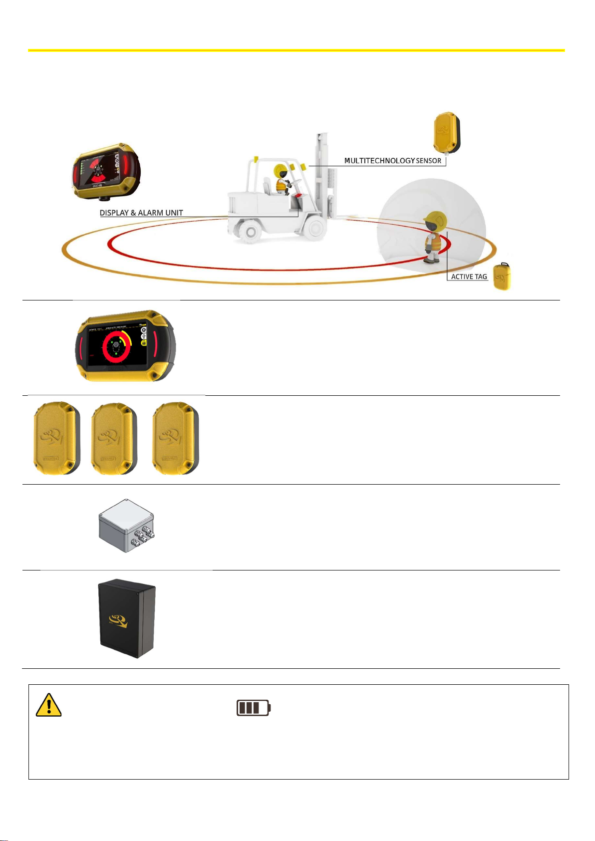
5 BASIC KIT COMPONENTS
The EGOpro Safe MOVE 4.0 basic kit consists of:
BASIC KIT COMPONENTS
1 P LX SAFEMOVE DIS - Display with cable
(plate and joint included)
3 P LX SAFEMOVE SENS4 - SAFE MOVE 4.0
multifunction sensor.
1 P LX SAFEMOVE HUB4 - HUB SAFEMOVE 4.0.
1 P LX SAFEMOVE CPU - CPU for SAFE MOVE.
(plate and joint included)
GENERAL CONSUMPTION VALUES
Consumption to the Hub up to 3 sensors 20W
Consumption of CPU with active display 15W
Consumption of CPU with display on standby 1W
The technical materials and information contained in this document are strictly confidential and the exclusive property of Advanced Microwave Engineering s.r.l.
These materials and information are intended solely for the purpose designated and may not be used otherwise.
It is not permitted to disclose or reproduce them in whole or in part without express written permission.
9
Page 10
SYSTEM OPERATION
6 SYSTEM OPERATION
The solution offered by the EGOpro Safe MOVE 4.0 proximity warning & alert system minimises the potential for accidents
between forklifts and operators on foot in common working areas. Through visual and sound alarms, the system warns
the driver, in real time, of the presence and position of pedestrian workers wearing active PPE who enter the danger
zones around the vehicle in motion.
With the system, the driver can promptly take the most appropriate safety measures to avoid hitting other pedestrian
workers or other vehicles.
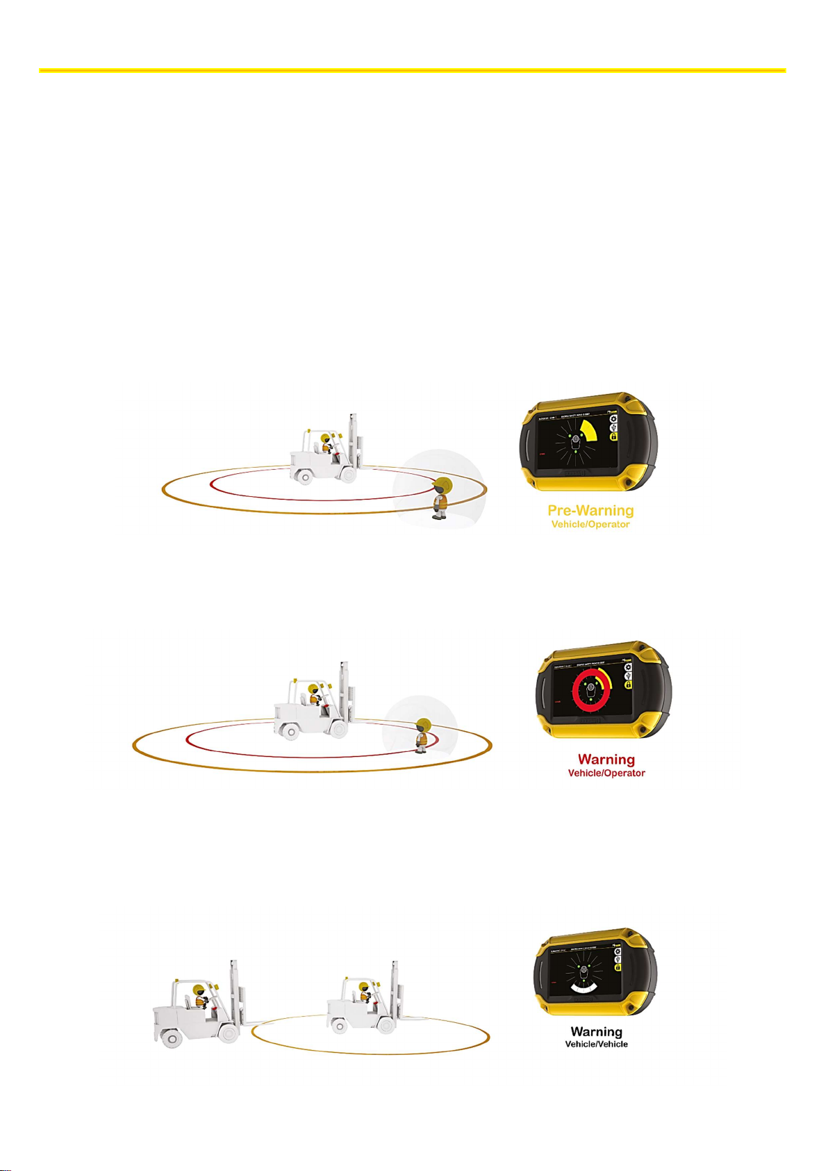
Thanks to a multifunction sensor, the system detects pedestrian workers wearing a TAG, in two stages:
6.1 PEDESTRIAN WORKER PRE-WARNING
PRE-WARNING| The activation range can be configured up to 50 m with the control of a relay contact.
By means of a visual and sound alarm, the system warns the driver about the presence and position of the pedestrian
worker.
6.2 PEDESTRIAN WORKER WARNING
WARNING| The activation range can be configured up to 5-m with the control of a contact relay.
By means of a visual and sound alarm, the system warns the driver about the presence of the pedestrian worker with a
red circle and by switching on the lateral LEDs.
6.3 VEHICLE-VEHICLE WARNING
VEHICLE-VEHICLE WARNING| When a vehicle equipped with the EGOpro Safe MOVE 4.0 system gets into the sensor
activation area. The activation range can be configured up to 100 m.
By means of a visual and sound alarm, the system warns the driver about the presence and position of the other vehicle.
10
The technical materials and information contained in this document are strictly confidential and the exclusive property of Advanced Microwave Engineering s.r.l.
These materials and information are intended solely for the purpose designated and may not be used otherwise.
It is not permitted to disclose or reproduce them in whole or in part without express written permission.
Page 11
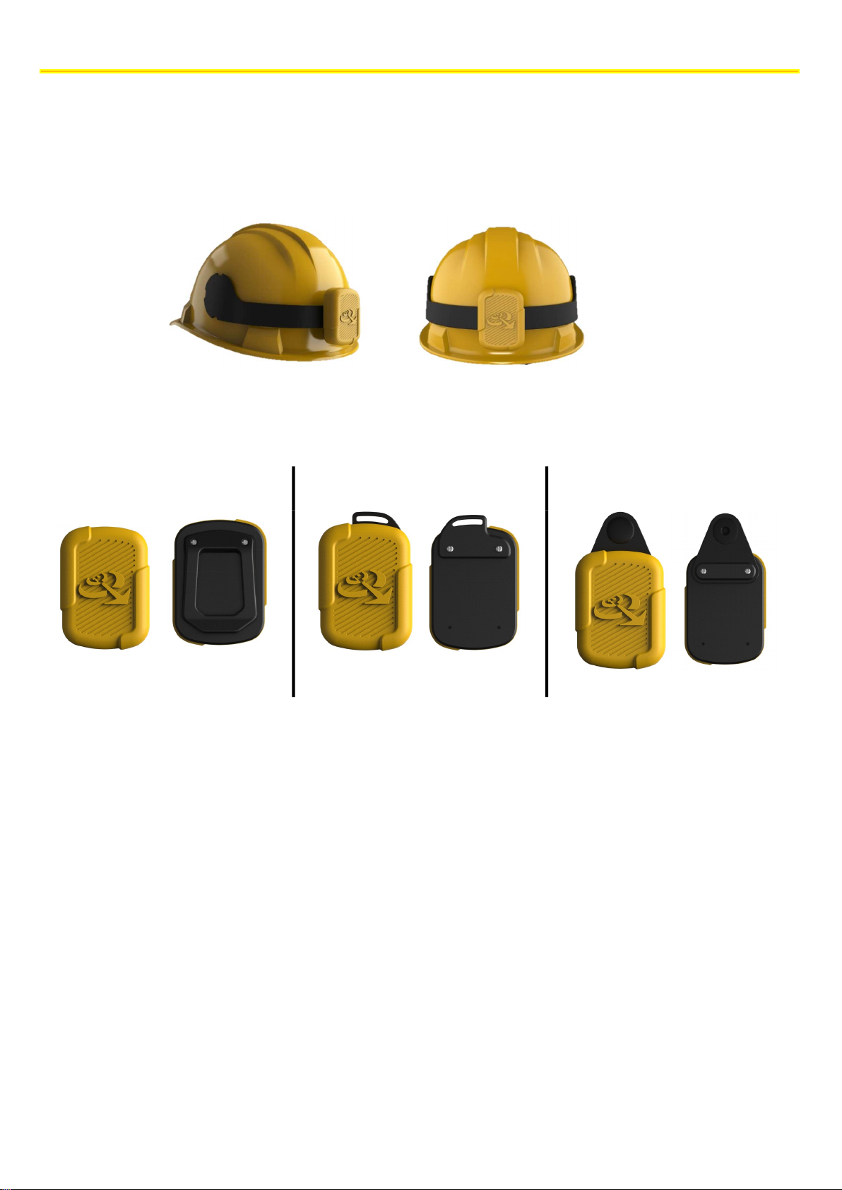
PLACING TAGS
Clip for band
Slot for strap
Snap fastener
Use the screws supplied: 2.2
X7
Use the screws supplied: 2.2
X6
Use the screws
supplied: 2.2
X7
7 PLACING TAGS
7.1 HELMET TAG FITTING
To fit the PLX TAGSAFETY 03TH Tag, you first need to clean the helmet. Then, you have to suitably remove the grease
from the surface with the napkin supplied. Now you can affix the Tag as shown in the figure.
7.2 WEARABLE TAG ACCESSORIES
The wearable Tag is supplied together with a series of accessories that guarantee a wide range of options for wearing it.
The technical materials and information contained in this document are strictly confidential and the exclusive property of Advanced Microwave Engineering s.r.l.
These materials and information are intended solely for the purpose designated and may not be used otherwise.
It is not permitted to disclose or reproduce them in whole or in part without express written permission.
11
Page 12
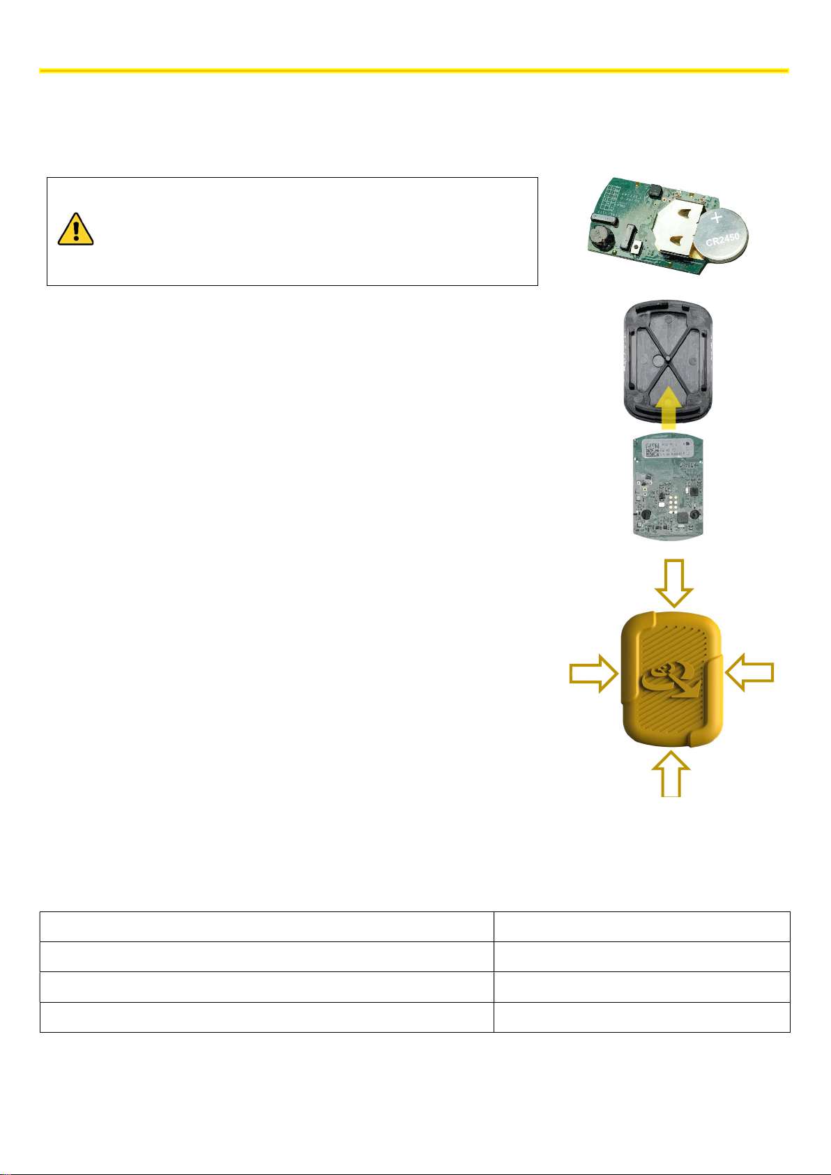
PLACING TAGS
Caution: respect the correct polarity; insert the battery with the
7.3 PROCEDURE FOR CHANGING THE BATTERY
The battery inside the Tag is a CR2450 button cell battery.
To replace it, remove the yellow rubber piece, and then replace the battery.
negative pole towards the circuit.
While replacing the battery in the helmet tag, be careful not to
damage or disconnect the small coaxial cables connected to the
circuit board.
Once the battery has been replaced, make sure that the Tag has turned on
correctly. Depending on the version, it can emit a long initial sound followed by
three short sounds, or only one long flash followed by three short flashes of the
LED on the board.
If this does not happen, the device has not started correctly; contact the
manufacturer.
Put the tag back into the slot at the correct position as shown in the figure
opposite.
Position the soft rubber piece back into place, and then press it in all directions
so that it correctly adheres to the rigid piece.
Battery life depends on the daily activations of the tag when it is near a vehicle equipped with the anti-collision system.
Typically, there are three identified scenarios; the following table summarises the battery life associated to each of
them:
Type of scenario Estimated duration in years
Driver use* 1.5
Pedestrian worker with high interference with vehicles 2
Pedestrian worker with low interference with vehicles 3/5
*Equipped with an inhibitor in the cabin (FILTERSENS)
12
The technical materials and information contained in this document are strictly confidential and the exclusive property of Advanced Microwave Engineering s.r.l.
These materials and information are intended solely for the purpose designated and may not be used otherwise.
It is not permitted to disclose or reproduce them in whole or in part without express written permission.
Page 13
INSTALLATION ON THE VEHICLE
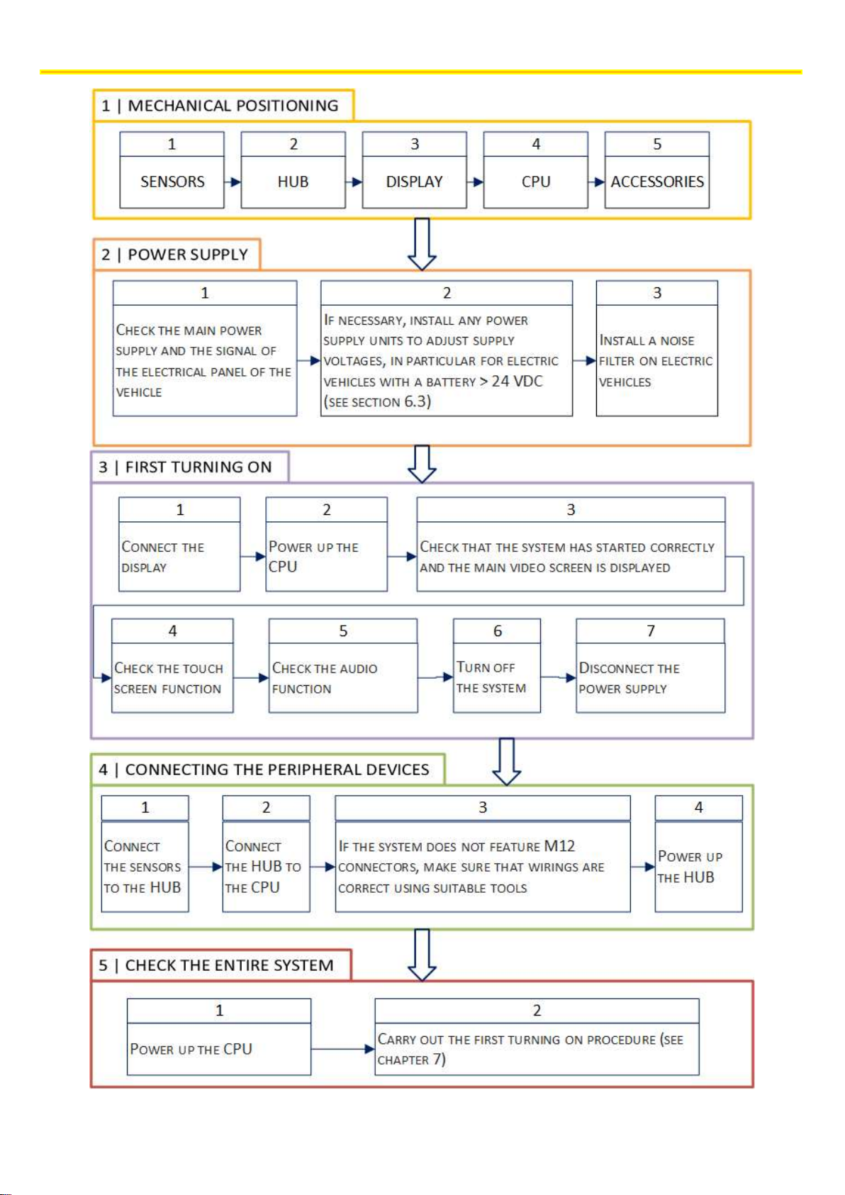
8 INSTALLATION ON THE VEHICLE
8.1 SYSTEM ARCHITECTURE AND GENERAL INSTRUCTIONS
The basic KIT of the EGOpro Safe MOVE 4.0 system that is installed on the vehicle consists of the following devices:
3 Sensors
1 HUB
1 CPU
1 Display
It is advisable to follow the workflow indicated in the following table and described in detail in the subsequent sections in
order to minimise installation problems.
The technical materials and information contained in this document are strictly confidential and the exclusive property of Advanced Microwave Engineering s.r.l.
These materials and information are intended solely for the purpose designated and may not be used otherwise.
It is not permitted to disclose or reproduce them in whole or in part without express written permission.
13
Page 14
INSTALLATION ON THE VEHICLE
14
The technical materials and information contained in this document are strictly confidential and the exclusive property of Advanced Microwave Engineering s.r.l.
These materials and information are intended solely for the purpose designated and may not be used otherwise.
It is not permitted to disclose or reproduce them in whole or in part without express written permission.
Page 15
INSTALLATION ON THE VEHICLE
8.2 POSITIONING THE DEVICES
To position the devices, take into account the operation characteristics of the system, the mechanical restrictions and the
IP protection degree of the devices.
For these reasons, two categories are identified:
Devices outside the driver’s cabin
Sensors are usually positioned outside the driver’s cabin, except for
exceptional cases such as exposure to high temperatures.
Devices inside the driver’s cabin
CPU and Display: due to their function and the IP protection degree, they
must be inside the driver’s cabin or, in any case, in a protected position.
The HUB can be positioned either outside or inside the driver’s cabin due to both its operation and its high degree of
protection.
The 433MHz whip aerial antenna, which is present on the HUB, must be fitted outside
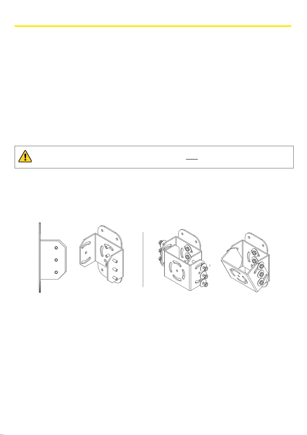
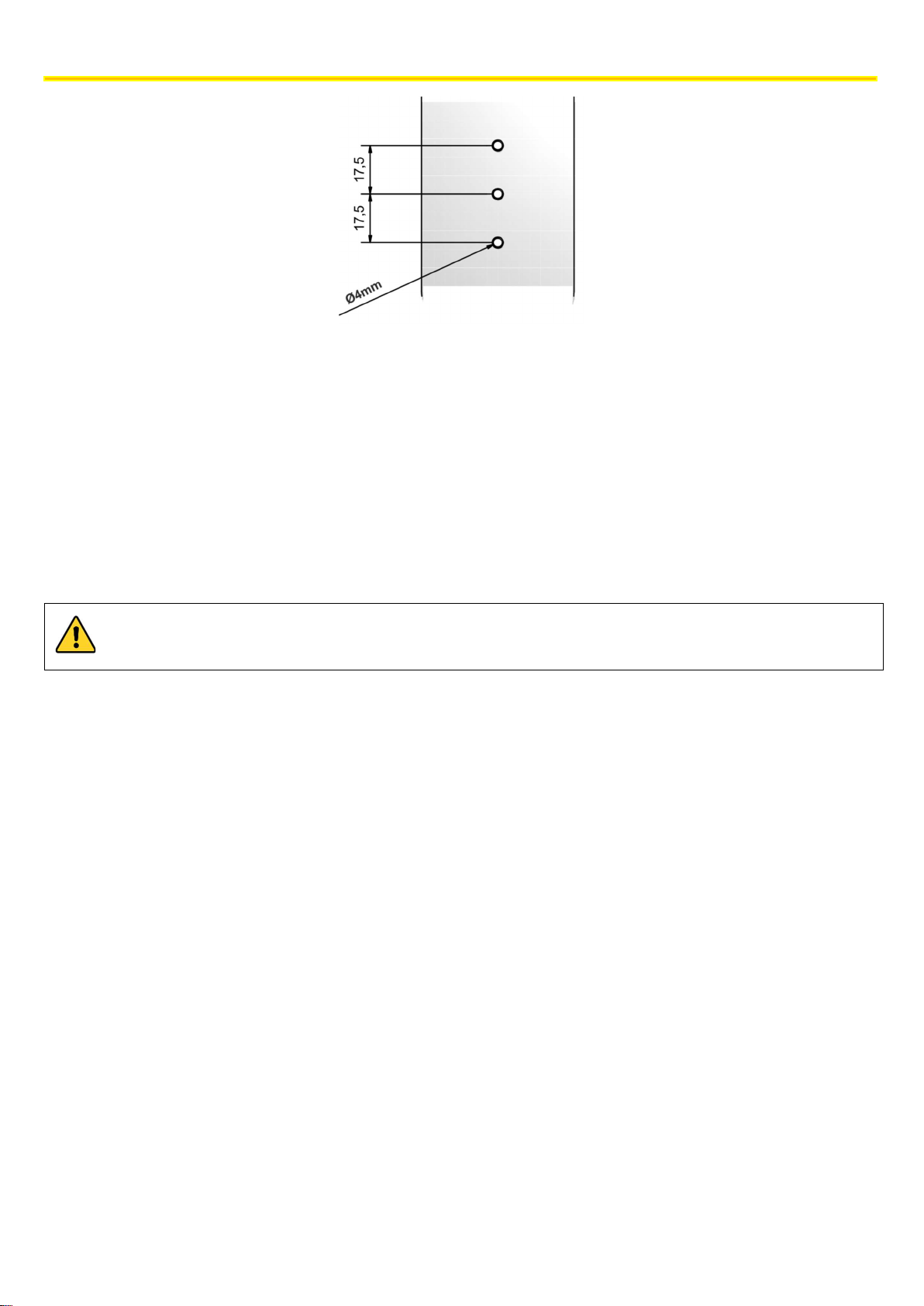
The Display and the Sensors must be correctly oriented: for this reason, they are supplied with a mounting plate and a
mechanical joint onto which the support that is necessary for holding the device must be fitted.
The joint, which is made up of 2 U-shaped mechanical pieces, has been designed to be easily connected to the plate that
is present on the devices.
Find below the heights for the possible holes to be used for fixing it to the plate.
The technical materials and information contained in this document are strictly confidential and the exclusive property of Advanced Microwave Engineering s.r.l.
These materials and information are intended solely for the purpose designated and may not be used otherwise.
It is not permitted to disclose or reproduce them in whole or in part without express written permission.
15
Page 16
INSTALLATION ON THE VEHICLE
8.2.1 Positioning the control unit (CPU)
The CPU is the basic element of the system and it can be positioned at any point inside the driver's cabin. The position of
the CPU must not obstruct the driver’s and the vehicle operability, and it should be handy to connect the HUB and the
Display.
To fix the CPU, use the 4 holes on the box that can be accessed by removing the device cover.
When choosing the position, keep in mind that there are usable outputs on the CPU to make it conveniently accessible
and not to be obstructed during assembly. For example, the USB port can be used to download data and for servicing.
The CPU has an IP 20 protection degree, and the connection cable is 2.50 m long.
16
The technical materials and information contained in this document are strictly confidential and the exclusive property of Advanced Microwave Engineering s.r.l.
These materials and information are intended solely for the purpose designated and may not be used otherwise.
It is not permitted to disclose or reproduce them in whole or in part without express written permission.
Page 17
INSTALLATION ON THE VEHICLE
When installing the Display and
laying the connection cable, be careful so that they do not disturb the driver’
8.2.2 Positioning the Display
The Display must be positioned inside the driver’s cabin in accordance with the driver’s visibility requirements and taking
into account the CPU position: the connection cable between Display and CPU is 2.5 m long.
movements and the driver’s visibility remains unaffected.
The Display has an IP 20 protection degree. Position it in the cabin, in an area protected from the elements.
The cable that carries the video signal from the CPU to the Display is double-shielded; therefore, handle the
cable carefully and avoid bending radii of less than 5 cm in order to avoid damaging the internal conductors,
in particular the ends on the connector side and the Display housing inlet.
If the display is mounted upside down to facilitate installation, the rotation of the video can be changed from
the advanced settings of the system (contact technical support for help).
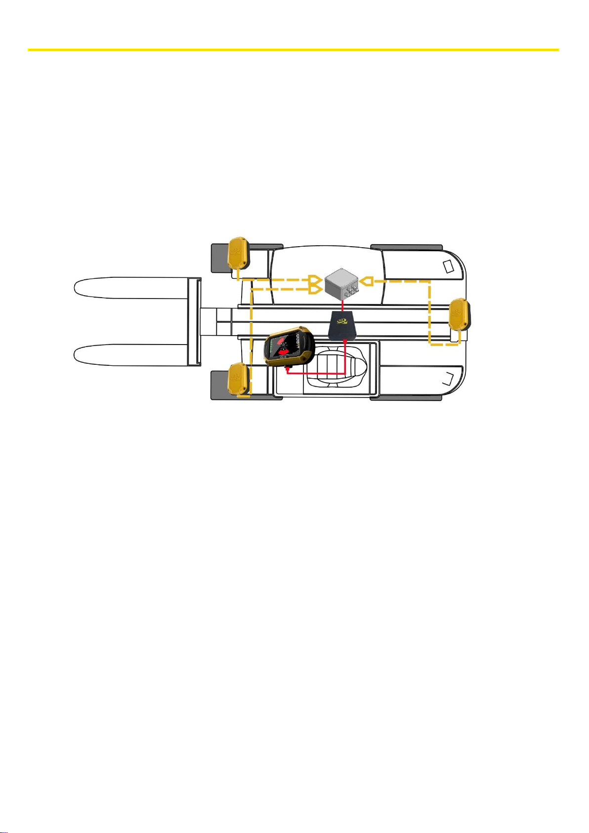
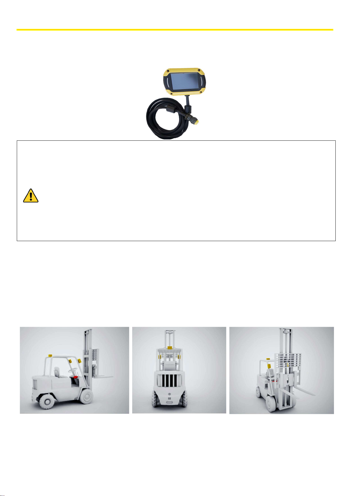
8.2.3 Positioning the sensors
The basic Kit is made up of 3 sensors that are sufficient to cover small and medium-sized vehicles. The installation must
optimise coverage around the vehicle taking into account the type of mobility of the vehicle.
The most common installation includes 2 Sensors on the front/loading side, driven forward, and 1 Sensor on the rear
side/driven in reverse.
NOTE: the number of sensors can be extended up to 8 by adding suitable components (see section 8.5).
Find below the reference diagram for a counterbalanced forklift truck.
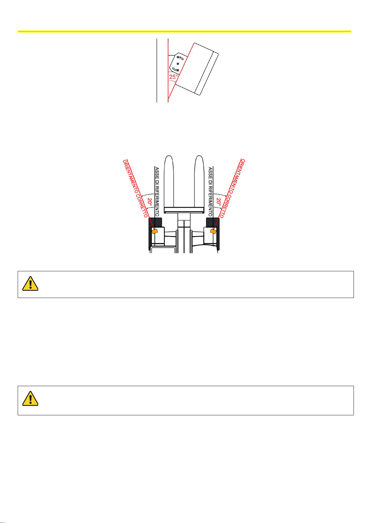
The sensors must be so positioned on the perimeter of the vehicle to have maximum visibility between Sensors and TAG.
On small/medium-sized vehicles, they are usually positioned on the uprights immediately below the roof and with a 25 °
downward inclination.
The technical materials and information contained in this document are strictly confidential and the exclusive property of Advanced Microwave Engineering s.r.l.
These materials and information are intended solely for the purpose designated and may not be used otherwise.
It is not permitted to disclose or reproduce them in whole or in part without express written permission.
17
Page 18
INSTALLATION ON THE VEHICLE
To position the external antenna, also refer to the HUB connections (see section
8.3.4
).
NOTE: the mechanical joint supplied can be used to obtain the desired inclination.
Front sensors must have a slight orientation towards the outside. For example, for a counterbalanced vehicle, they must
be positioned outside the moulding of the fork/gripper holder mounting, and they must have an orientation angle towards
the outside of around 20°.
Be careful not to place the sensors behind obstacles such as the turret of the forks or the vehicle chassis.
For the best operation of the sensors, they must be installed in areas that are as free as possible.
8.2.4 Positioning the HUB
The HUB can be positioned at any point inside or outside the driver’s cabin, even in a hidden area, but the external RF
antenna (whip aerial antenna), connected to the HUB by means of a 1.5m-long cable, must be outside the driver’s cabin
in vertical position.
The position of the HUB must not obstruct the driver’s and the vehicle operability, and it should be handy to
connect the Sensors and the CPU.
18
The technical materials and information contained in this document are strictly confidential and the exclusive property of Advanced Microwave Engineering s.r.l.
These materials and information are intended solely for the purpose designated and may not be used otherwise.
It is not permitted to disclose or reproduce them in whole or in part without express written permission.
Page 19
INSTALLATION ON THE VEHICLE
CPU-HUB Connection
HUB
-
SENSOR Connection
VDC AWG 26
AWG 24
VDC AWG 26
AWG 24
12 V
20m 40m
12 V
3m 6m
24 V
50m 100m
24 V
25m 50m
8.3 CONNECTIONS
8.3.1 General instructions
The necessary connections on the systems can be summarised in two categories:
Data Connections
Power Supply Connections
Data Connections
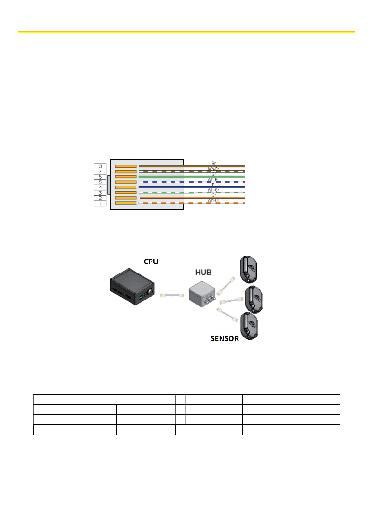
The data connection between the system devices is established with a UTP cable. As a minimum requirement, it is
recommended to use a UTP cable belonging to category 5E or higher. In the case of RJ45 connections, the same sequence
of colours must be followed on each cable end, and it is recommended to use the sequence of colours according to
Standard TIA/EIA-568-B.
The data connection is between Hub-CPU and between Sensors-Hub.
The maximum length of the connection depends on the supply voltage of the system and on the cross section of the UTP
cable (AWG). For convenience purposes, the reference tables of both connections are provided.
The technical materials and information contained in this document are strictly confidential and the exclusive property of Advanced Microwave Engineering s.r.l.
These materials and information are intended solely for the purpose designated and may not be used otherwise.
It is not permitted to disclose or reproduce them in whole or in part without express written permission.
19
Page 20
INSTALLATION ON THE VEHICLE
Within the 12÷24 VDC power supply range, the voltage of the direct positive wire (V
) and of the line under
Power Supply Connection
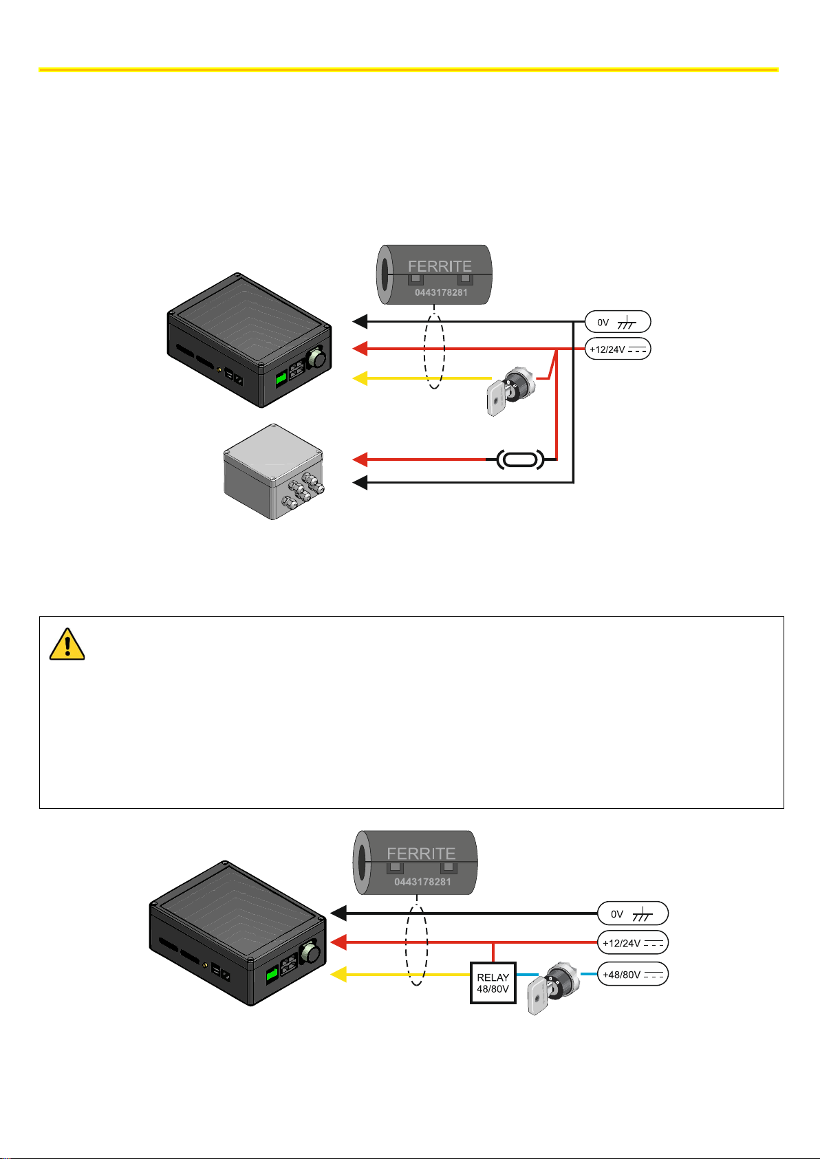
The system must be powered in direct current (VDC) ranging from 12V to 24V (±10%).
The devices to be powered are the CPU and the HUB. A direct positive wire (VIN) and a positive wire under key (VQ) must
arrive to the CPU, whereas only the direct positive wire protected by an ATO fuse (4A/32V) must arrive to the Hub.
Apply the supplied Fair Rite 0443178281 ferrite on the CPU power cables.
CPU
HUB
ATO 4A 32V
For the power supply connections, it is recommended to use an AWG 18 /0.75mm2 cable or a cable with a higher cross
section.
IN
key (VQ) do not have to be the same.
In some cases, the voltage present on the wire under key is not within the range foreseen by the system. In
these cases, one solution would be using a relay at the same voltage available for changing over the forward
voltage
For vehicles with a battery with power higher than 24V, such as electric vehicles for heavy work with 48V or
80V, follow the power supply scheme specified in chapter 24.6; use the indicated isolated power supply unit
or an equivalent model whenever possible.
CPU
20
The technical materials and information contained in this document are strictly confidential and the exclusive property of Advanced Microwave Engineering s.r.l.
These materials and information are intended solely for the purpose designated and may not be used otherwise.
It is not permitted to disclose or reproduce them in whole or in part without express written permission.
Page 21
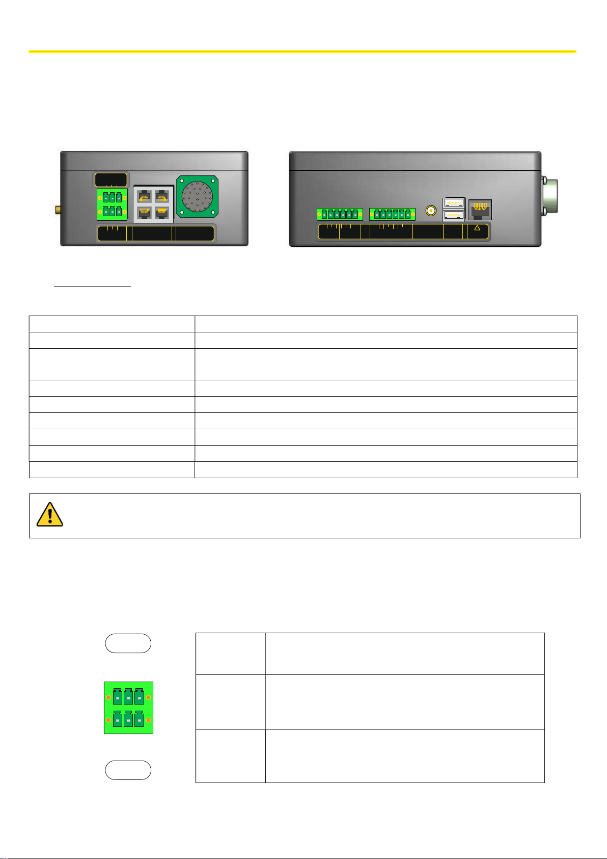
8.3.2 CPU Wiring
GPS
Power supply/turning
-on To power the CPU and some of the accessories that can be installed
RS 232
To connect the BADGE module
SENSORS
To connect the HUB and other accessories of the system (FILTER SENS, INDOOR
Display Connector
To connect the display, the touchscreen and the audio
Relay
Clean contacts to connect to the vehicle
I/O I/O signals for managing additional functions
GPS Antenna
To connect the antenna of the GPS module (if any)
USB To connect periph
erals devices for downloading data/updates/maintenance
POE LAN
To connect the Wi
-
Fi Module and the cellular router
All the devices of the system must be connected to the CPU.
The available connectors are as follows:
PWR-IN
+VIN
GND
+VQ
A
B
P R
C
N
S T
a
b
U
D
M
Z
c
V
E
WXY
L
F
K
GHJ H
INSTALLATION ON THE VEHICLE
TX
RS232
Power supply
/turning-on
RS 232
NO
COM
NC
NO
COM
NC
C1
C2
GND
GND
O1
GND
RX
SENSORS DISPLAY
HUB
Sensors
Display
connector
Relay I/O
RELAY1 RELAY2
I/O
O2
GPS
USB LAN
(RJ45)
USB1
USB2
!
LAN
POE
POE
SPEED SENSOR, SHOCK SENSOR)
Caution: this is a POE 10/100 LAN port, mode B, "DC on spares" and therefore, it must not be used with devices
that are not suitable for this type of connection (e.g., notebooks, Ethernet switch, etc.)
The CPU is powered at 12-24V, and it needs a specific +VQ line (under key). The CPU remains turned on even when the
vehicle is off in low consumption mode (stand-by). Activation takes place when voltage is supplied to the VQ terminal. This
enables a quick turning-on of the system.
PWR IN
+VIN 12/24 VDC power supply
Q
+VINGND
+V
GND Negative supply voltage
TX
GND
RS232
RX
+VQ
12/24 VDC positive voltage of the turning-on signal of the
board
The technical materials and information contained in this document are strictly confidential and the exclusive property of Advanced Microwave Engineering s.r.l.
These materials and information are intended solely for the purpose designated and may not be used otherwise.
It is not permitted to disclose or reproduce them in whole or in part without express written permission.
21
Page 22
INSTALLATION ON THE VEHICLE
AWG 26
AWG 24
12 V
3m 6m
24 V
25m 50m
To connect the HUB, an UTP cable belonging to Cat. 5e or higher must be connected to one of the Sensors ports.
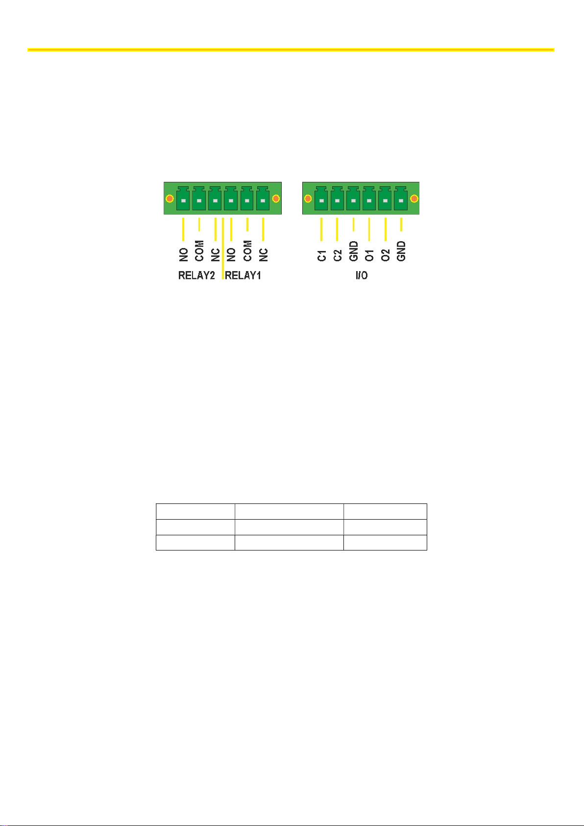
The CPU has 2 relays that can be controlled independently. There are 3 pins for each relay:
- NO | normally open
- C | common
- NC | normally closed.
The default configuration indicates that:
Relay 1 (RL1) remains active until the system detects one or more TAGs in the long-range
detection area, i.e. in pre-Warning.
Relay 2 (RL2) remains active until the system detects one or more TAGS in the short-range
detection area, i.e. in Warning.
The configuration of the relays can be modified from the advanced settings of the system (contact technical support for
help).
8.3.3 Connecting sensors
The sensors are connected to the HUB with 8 poles UTP cables. The maximum connection length is linked to the supply
voltage and the type of cable
Figure 1 Maximum length of the HUB sensor connection cables according to the type of cable and the power supply
The UTP cable must be connected to the J1 connector inside the sensor box with an RJ45 connector.
22
The technical materials and information contained in this document are strictly confidential and the exclusive property of Advanced Microwave Engineering s.r.l.
These materials and information are intended solely for the purpose designated and may not be used otherwise.
It is not permitted to disclose or reproduce them in whole or in part without express written permission.
Page 23
INSTALLATION ON THE VEHICLE
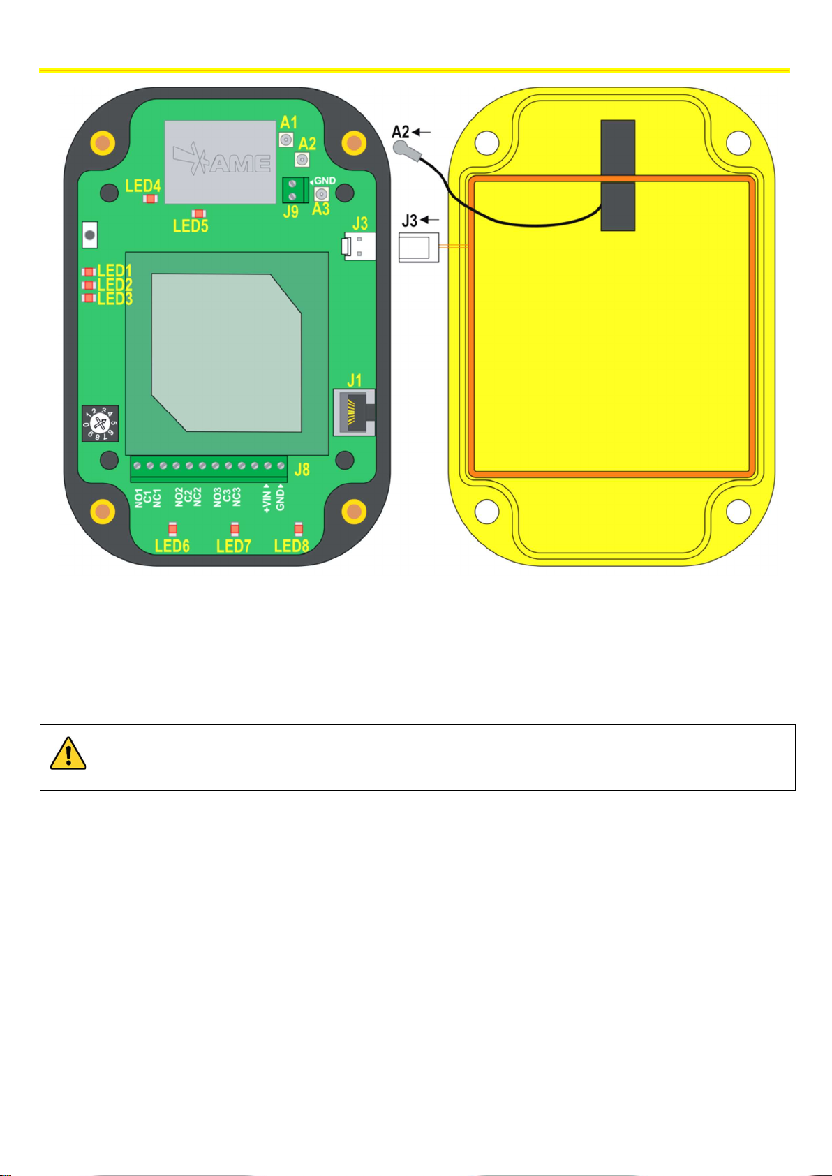
While the sensor is
closing back, make sure that the A2 and J3 connectors are connected; prevent the cables
A1 – MW transmission antenna uFL connector (antenna already connected) LED1 – vehicle-vehicle reception signal (flashing)
A2 – MW reception antenna uFL connector (antenna to be connected)
A3 – RF test uFL connector LED3 – ON status indicator
J9 – RF antenna connector (antenna already connected) LED4 – MW status indicator (flashing) and diagnosis error (steady off)
J3 – LF antenna connector (antenna to be connected) LED5 – RF status indicator (flashing) and diagnosis error (steady off)
J1 – data BUS and power supply connector LED6 – Relay 1 active/inactive (ON/OFF)
J8 – relay terminal board and stand-alone power supply LED7 – Relay 2 active/inactive (ON/OFF)
LED8 – Relay 3 active/inactive (ON/OFF)
LED2 – LF transmission (flashing) and diagnosis error (steady off)
from finishing above the patch antenna (central panel of the figure on the left). Make sure that the sealing Oring is placed back in its housing.
Immediately after the UTP cable comes out of the box, insert a 74271132S ferrite or an equivalent type.
The technical materials and information contained in this document are strictly confidential and the exclusive property of Advanced Microwave Engineering s.r.l.
These materials and information are intended solely for the purpose designated and may not be used otherwise.
It is not permitted to disclose or reproduce them in whole or in part without express written permission.
23
Page 24
INSTALLATION ON THE VEHICLE
The device is powered in direct current with a voltage between 12/24 V.
The antenna support must be kept isolated from the
chassis
of the vehicle
.
AWG18/0.75mm2
POWER SUPPLY CONNECTOR
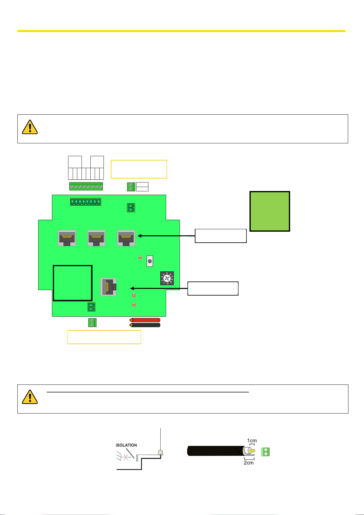
8.3.4 Connecting the HUB
Connect the sensors to BUS 2 by means of UTP cable following the indications given in the sensor connection section.
When crimping the UTP cable, follow the same sequence of colours on each cable end.
Connect the HUB to the CPU by means of the BUS 1 connector using a cable belonging to CAT. 5e or higher.
Connect the power supply to the EXT POWER connector using an AWG 18/0.75 mm2 bipolar cable or a cable with a higher
cross section.
Insert the ferrite, 74271132S type or equivalent, in the power cable
The power supply to the device must be limited to a maximum of 4A/32V. Use a fuse directly fitted on the
positive-pole conductor.
RL2
C
NO
1
OUTPUT
RL1
GND
NC
NCCNO
+3.3V
CONNECTOR
EXTERNAL RF
ANT RF
BUS2 BUS2 BUS2
BUS1
EXT PWR
+12/24VDC
GND
GND
ANT
ADR_HUB
BUS2 TX
BUS2 RX
It is recommended to keep the
coaxial antenna cable away from
the area highlighted by the square
SENSOR INPUT
SW1
CPU INPUT
Connect the antenna supplied together with the system. Observe the polarity. The braiding should be on GND and the
central conductor on 'ANT'.
Observe the measurements shown in the figure to strip the RG58 cable of the antenna. Stripping the cable too
much may impair the correct RF performance of the system.
24
The technical materials and information contained in this document are strictly confidential and the exclusive property of Advanced Microwave Engineering s.r.l.
These materials and information are intended solely for the purpose designated and may not be used otherwise.
It is not permitted to disclose or reproduce them in whole or in part without express written permission.
Page 25

INSTALLATION ON THE VEHICLE
If the device is installed on electric vehicles, add a power line filter, for instance an FN2090-3-06 Schaffner filter.
If requested, the relays present on the board can be connected following the diagram foreseen.
The default configuration indicates that:
Relay 1 (RL1) remains active until the system detects one or more TAGS in the short-range
detection area, i.e. in Warning.
Relay 2 (RL2) is activated with a delay time, which can be configured once relay 1 is activated.
The configuration of the relays can be modified from the advanced settings of the system (contact technical support for
help).
The technical materials and information contained in this document are strictly confidential and the exclusive property of Advanced Microwave Engineering s.r.l.
These materials and information are intended solely for the purpose designated and may not be used otherwise.
It is not permitted to disclose or reproduce them in whole or in part without express written permission.
25
Page 26

INSTALLATION ON THE VEHICLE
DEVICE
CODE
HUB PLX SAFEMOVE HUB 4M
SENSOR
PLX SAFEMOVE SENS 4M
CABLE
POLES
LENGTH (m)
AWG
CODE
8.4 INSTALLING THE SYSTEM WITH M12 CONNECTORS
The PLX SAFEMOVE SENS 4 and PLX SAFEMOVE HUB 4 devices are available in a version fitted with M12 connectors.
Such version has been designed in order to make the system installation and removal simpler and quicker.
The table below summarises the codes used in the system fitted with connectors.
RJ45-M12f CPU-HUB CONNECTION CABLE 8 5 24 M12AFRJ45CABLE5M
M12m-M12f HUB SENSOR CONNECTION CABLE 8 5 24 M12AMFCABLE5M
HUB POWER SUPPLY AND RELAY CONNECTION CABLE 12 5 24 M12AFPAN12P5M
The section below indicates the functions of the different connectors and connections for the HUB power supply and relay
HUB power supply and relay
1
2
3
Connector for HUB-CPU
connector
connection cable
Connection connectors
towards sensors
26
The technical materials and information contained in this document are strictly confidential and the exclusive property of Advanced Microwave Engineering s.r.l.
These materials and information are intended solely for the purpose designated and may not be used otherwise.
It is not permitted to disclose or reproduce them in whole or in part without express written permission.
Page 27

INSTALLATION ON THE VEHICLE
CPU-HUB Connection
HUB
-
SENSOR Connection
VDC AWG 26
AWG 24
VDC
AWG 26
AWG 24
12 V
20m 40m
12 V
3m 6m
24 V
50m 100m
24 V
25m 50m
FEMALE (FRONT VIEW)
PIN
Colour Function
1 Brown VDC
2 Blue VDC
3 White GND
4 Green GND
5 Pink Normally Open Relay 1
6 Yellow Common Relay 1
7 Black Normally Closed Relay 1
8 Grey Normally Open Relay 2
9 Red Common Relay 2
10 Violet Normally Closed Relay 2
11 Grey-Pink Not Used
12 Red-Blue Not Used
8.4.1 LENGTH OF CONNECTIONS
The cables supplied are 5-m long, and they are AWG 24. If longer connections are to be made between HUB and sensors
and between HUB and CPU, M12 AMF CABLES (5M) may be used as extensions.
The technical materials and information contained in this document are strictly confidential and the exclusive property of Advanced Microwave Engineering s.r.l.
These materials and information are intended solely for the purpose designated and may not be used otherwise.
It is not permitted to disclose or reproduce them in whole or in part without express written permission.
27
Page 28

INSTALLATION ON THE VEHICLE
SENSOR PORTS
8.5 EXPANSION OF THE NUMBER OF SENSORS
The system can manage up to a maximum of 8 sensors. To add additional sensors to the basic kit, one or more splitters
must be installed, as required:
- up to 6 sensors, one splitter is needed
- for 7-8 sensors, two splitters are needed
The splitter must be connected to one of the 3 ports available in the HUB, and this makes 4 ports available for connecting
just as many sensors.
F1 F3
F4
J5
J2
F2
J3
J4
HUB INPUT
LED TX
J1
LED PWRON
LED RX
Find below an example of the configuration of an EGOpro Safe Move system with 8 sensors.
HUB
SPLITTER 1
28
SPLITTER 2
The technical materials and information contained in this document are strictly confidential and the exclusive property of Advanced Microwave Engineering s.r.l.
These materials and information are intended solely for the purpose designated and may not be used otherwise.
It is not permitted to disclose or reproduce them in whole or in part without express written permission.
Page 29

INSTALLATION ON THE VEHICLE
Deceleration
Total
8.6 STOPPING DISTANCES AND ACTIVATION DISTANCES
When installing a safety supporting system to be used for reducing the risk of man-vehicle and vehicle-vehicle collisions,
it is necessary to take into account which activation distances have to be considered for the system operation. The purpose
of this is to adjust the system so that a truly helpful signal can be given to the pedestrian worker.
As a matter of fact, the distance at which a pedestrian worker wearing a Tag or a vehicle has to be detected in order to
give effective aid for the prevention of collisions depends on many factors such as:
Shape and dimension of the vehicle.
Reaction time of the detection system
Reaction time of the driver
Deceleration distance
Conditions of the ground
Even though formulating an accurate mathematical model of the vehicle stop physical phenomenon is very complex, it
can be schematised following a simplified model in order to draw attention to the main physical phenomena involved.
8.7 Vehicle deceleration and driver's response distances
The space/distance a vehicle needs to stop safely must be clearly assessed. Firstly, evaluate the deceleration distance- the
distance the forklift truck needs to reach zero speed starting from a given speed from the instant the braking system is
actuated. In turn, this space depends on the speed of the forklift truck, the maximum deceleration set in the parameters
of the vehicle, and the response time of the systems of the forklift truck.
Deceleration, as well as maximum speed, can be set to different values depending on the type of load, vehicle and ground.
The maximum distances for industrial vehicles are standardised by ISO 6292 that sets the maximum stopping distances
from the instant when the braking system is actuated. Such values will be taken as reference. The driver's reaction distance
is to be added to the acceleration distance afterwards. Such distance is associated to the time between the alert and the
driver's action stop the vehicle. As a normal practice, this response time is estimated in 1 second. By way of an example,
find below two charts with the values referring to deceleration space and total stopping space for two types of vehicles
defined in the standard.
Chart 1 Stopping distances as per ISO 6292 A1 (<16000 kg)
Speed
[km/h]
distance [m]
(ISO6292 A1)
Driver reaction
distance @1s [m]
braking
time [m]
3 0.8 0.8 1.6
4 1.3 1.1 2.4
5 1.8 1.4 3.2
6 2.2 1.7 3.8
7 2.5 1.9 4.5
8 2.9 2.2 5.1
9 3.3 2.5 5.8
10 3.6 2.8 6.4
11 4.0 3.1 7.0
12 4.4 3.3 7.7
13 4.7 3.6 8.3
14 5.2 3.9 9.1
15 5.8 4.2 10.0
The technical materials and information contained in this document are strictly confidential and the exclusive property of Advanced Microwave Engineering s.r.l.
These materials and information are intended solely for the purpose designated and may not be used otherwise.
It is not permitted to disclose or reproduce them in whole or in part without express written permission.
29
Page 30

INSTALLATION ON THE VEHICLE
Total
16 6.4 4.4 10.9
17 7.1 4.7 11.8
18 7.8 5.0 12.8
19 8.5 5.3 13.8
20 9.3 5.6 14.8
21 10.1 5.8 15.9
22 10.9 6.1 17.0
23 11.8 6.4 18.2
24 12.7 6.7 19.3
Chart 2 Calculation of stopping distance as per ISO 6292 A2 (<16000 kg)
Speed
[km/h]
3 0.9 0.8 1.8
4 1.4 1.1 2.5
5 2.1 1.4 3.4
6 2.5 1.7 4.1
7 2.9 1.9 4.8
8 3.3 2.2 5.5
9 3.7 2.5 6.2
10 4.1 2.8 6.9
11 4.5 3.1 7.6
12 5.0 3.3 8.3
13 5.4 3.6 9.0
14 6.0 3.9 9.8
15 6.7 4.2 10.8
16 7.4 4.4 11.9
17 8.2 4.7 13.0
18 9.1 5.0 14.1
19 9.9 5.3 15.2
20 10.9 5.6 16.4
21 11.8 5.8 17.6
22 12.8 6.1 18.9
23 13.8 6.4 20.2
24 14.9 6.7 21.6
Deceleration distance
[m] ISO6292 A2
Driver reaction
distance @1s [m]
braking
time [m]
30
The technical materials and information contained in this document are strictly confidential and the exclusive property of Advanced Microwave Engineering s.r.l.
These materials and information are intended solely for the purpose designated and may not be used otherwise.
It is not permitted to disclose or reproduce them in whole or in part without express written permission.
Page 31

INSTALLATION ON THE VEHICLE
8.8 System activation distances. Setting the powers transmitted
The section above dealt with how to calculate stopping distances for an industrial vehicle. When estimating the distances
at which a tag potentially in danger of collision should be detected, a distance margin should be considered as well. A zero
distance cannot and should not be set. Besides, the detection system has reaction times that have to be taken into account.
To these distances identified, we should add a value that can be calculated according to the chart below.
Speed [km/h] operational margin [m]
3 0.6
4 0.8
5 1.0
6 1.2
7 1.4
8 1.6
9 1.8
10 1.9
11 2.1
12 2.3
13 2.5
14 2.7
15 2.9
16 3.1
17 3.3
18 3.5
19 3.7
20 3.9
21 4.1
22 4.3
23 4.5
24 4.7
Now the detection distance we want can be calculated. For instance, if a system is installed in a forklift truck falling within
category A1, with a maximum speed of 12 km/h and manual braking, the total braking distance will be 7.7 m; some further
2.3 m should be added as margin, to a total distance of 10 meters.
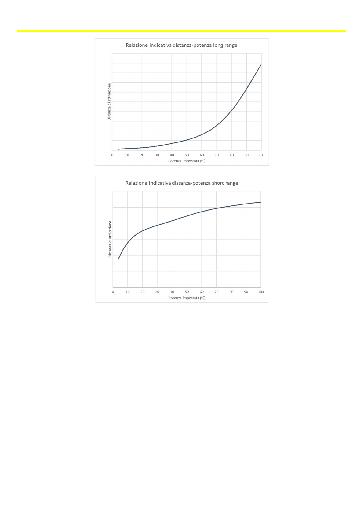
Once the desired distance is defined, adjust the power of the relevant sensors until a safe coverage for the distance
calculated is guaranteed. The distance previously identified is that from the interfering worker to the point of contact that
is closest to the forklift truck, which in a scenario of a front impact with a forklift truck is the forks.
Since the distance between the sensors and the first point of contact is not known a priori, and since the position of the
sensors may vary a lot, check the activation distance by applying control tests. Keep in mind that the low that governs the
power set and the activation distance is not linear. Find below some graphs that show the progress of the ratio between
these two values for both long range (pre-warning) and short range (warning).
The technical materials and information contained in this document are strictly confidential and the exclusive property of Advanced Microwave Engineering s.r.l.
These materials and information are intended solely for the purpose designated and may not be used otherwise.
It is not permitted to disclose or reproduce them in whole or in part without express written permission.
31
Page 32
INSTALLATION ON THE VEHICLE
8.9 Calculating the distance in case of vehicle-vehicle collision.
In case of vehicle-vehicle collision, we can consider that the same assessments described in the sections above are
applicable. The worst case to be considered is the one in which vehicles move at maximum speed against each other. In
this case, the calculated distance is twice the one that was calculated before.
32
The technical materials and information contained in this document are strictly confidential and the exclusive property of Advanced Microwave Engineering s.r.l.
These materials and information are intended solely for the purpose designated and may not be used otherwise.
It is not permitted to disclose or reproduce them in whole or in part without express written permission.
Page 33
TURNING-ON AND CONFIGURATION
9 TURNING-ON AND CONFIGURATION
9.1 TURNING ON THE SYSTEM
The system turns on automatically when the power supply (12/24VDC) is connected. While the system is turned on for the
first time, the initialisation screen is displayed.
Once initialisation is completed, the following screen is showed.
The first time the system is turned on takes more time.
The sensors, even if they are correctly installed, are not displayed by the system until the search procedure is
followed.
The technical materials and information contained in this document are strictly confidential and the exclusive property of Advanced Microwave Engineering s.r.l.
These materials and information are intended solely for the purpose designated and may not be used otherwise.
It is not permitted to disclose or reproduce them in whole or in part without express written permission.
33
Page 34
TURNING-ON AND CONFIGURATION
9.2 CONFIGURATION
In order for sensors to be recognised by the system, they must be configured from the configuration menu via the
touchscreen.
The following procedure describes the steps to be followed in order to configure the system and make sure that the
peripheral devices are correctly connected.
STEP 1
STEP 2
STEP 3
STEP 4
STEP 5
STEP 6
•Open the configuration menu
•Enter password
•Open the Sensors Configuration menu
•Open the Sensors Search menu
•Search sensors by ID
•Search sensor by position and save them to the system
9.2.1 STEP 1 | CONFIGURATION MENU
Press the CONFIGURATION icon to access the menu
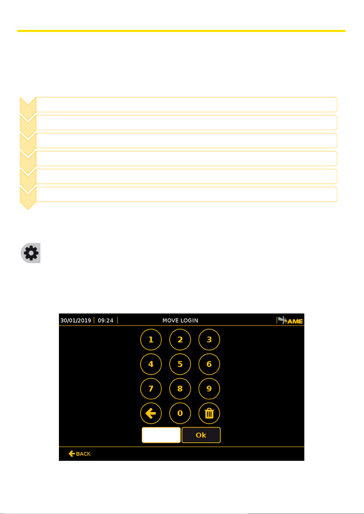
9.2.2 STEP 2 | ENTERING THE PASSWORD
To access the system configuration section, a password must be entered so that only the enabled user can view this screen.
The default access password is 1234. Enter the sequence and press OK.
34
The technical materials and information contained in this document are strictly confidential and the exclusive property of Advanced Microwave Engineering s.r.l.
These materials and information are intended solely for the purpose designated and may not be used otherwise.
It is not permitted to disclose or reproduce them in whole or in part without express written permission.
Page 35
TURNING-ON AND CONFIGURATION
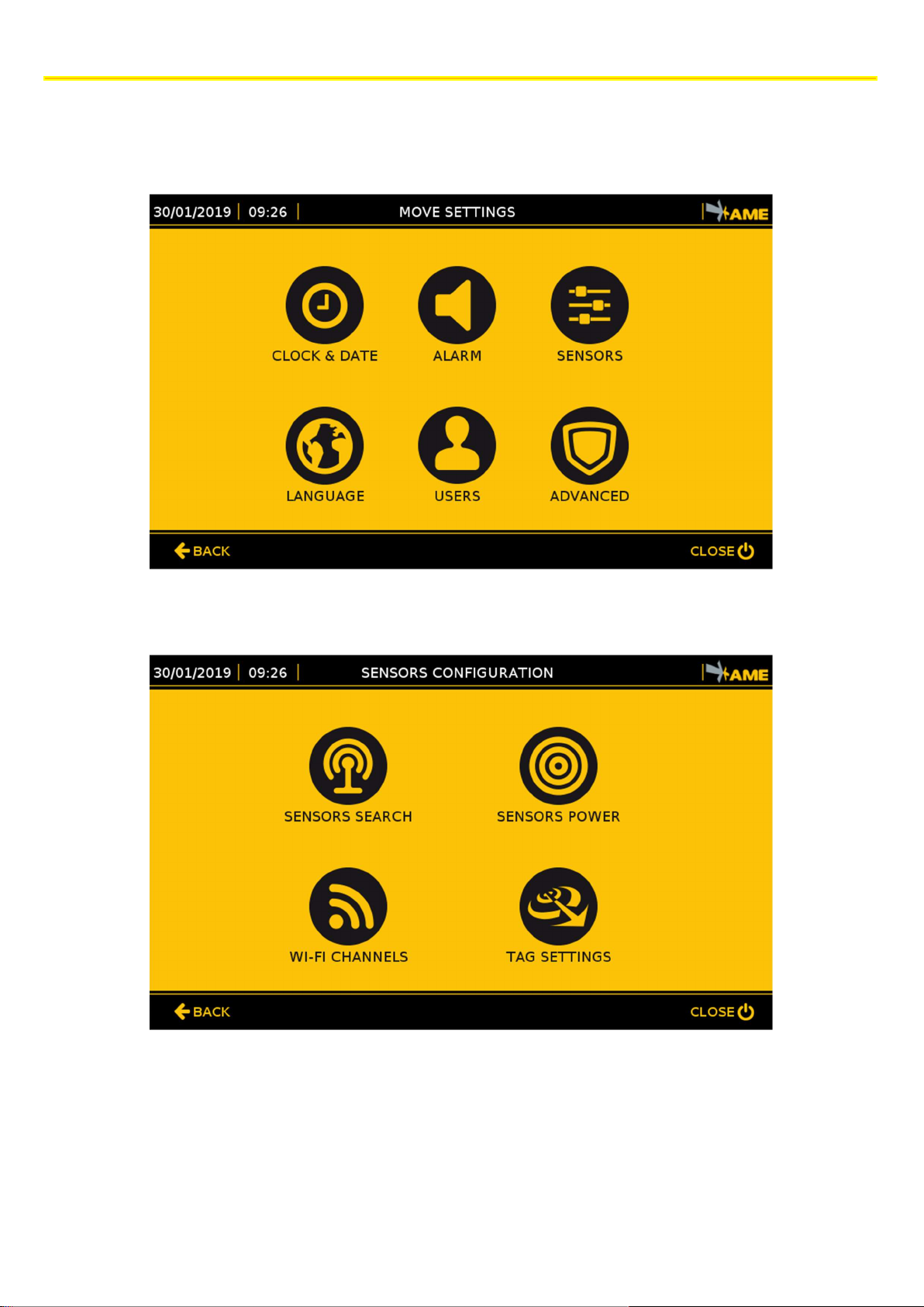
9.2.3 STEP 3 | SENSORS
The first screen when accessing the configuration menu is the following one. To configure the sensors press the SENSORS
key.
To configure the sensors press the SENSORS SEARCH key.
The technical materials and information contained in this document are strictly confidential and the exclusive property of Advanced Microwave Engineering s.r.l.
These materials and information are intended solely for the purpose designated and may not be used otherwise.
It is not permitted to disclose or reproduce them in whole or in part without express written permission.
35
Page 36
TURNING-ON AND CONFIGURATION
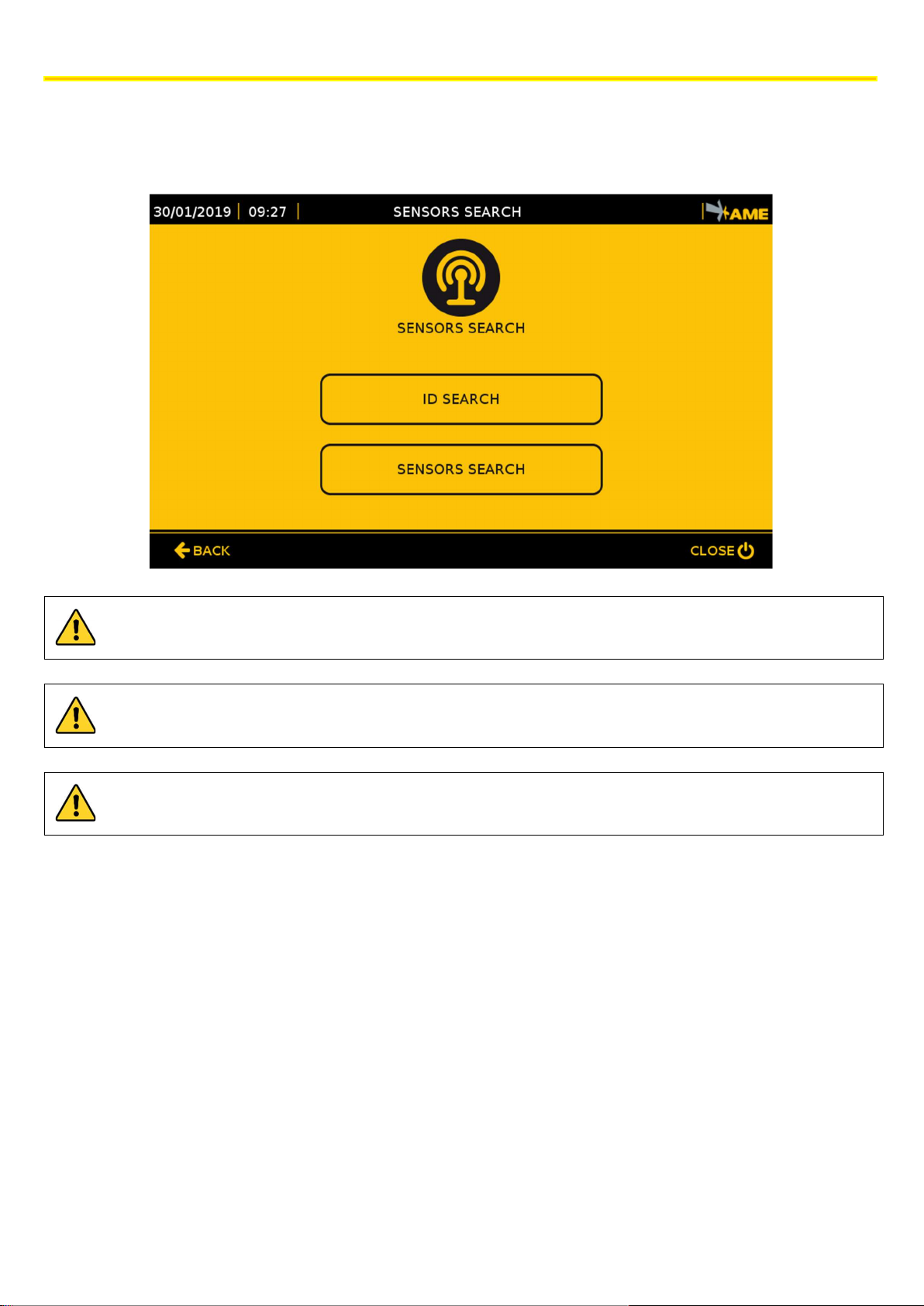
9.2.4 STEP 4 | SENSORS SEARCH
Each sensor has an unequivocal ID that must be saved to the CPU: first perform the ID SEARCH and then the SENSORS
SEARCH.
Before starting the ID SEARCH, make sure that the selectors present on the HUB and on each sensor are set to
0.
The sensors and the HUB, if they have an M12 connector, are already correctly set, and they must not be
opened.
Before starting the ID SEARCH note down the code (ID) (shown as FC: XX XX XX) indicated on each sensor in
order to be able to save it in the correct position.
36
The technical materials and information contained in this document are strictly confidential and the exclusive property of Advanced Microwave Engineering s.r.l.
These materials and information are intended solely for the purpose designated and may not be used otherwise.
It is not permitted to disclose or reproduce them in whole or in part without express written permission.
Page 37
TURNING-ON AND CONFIGURATION
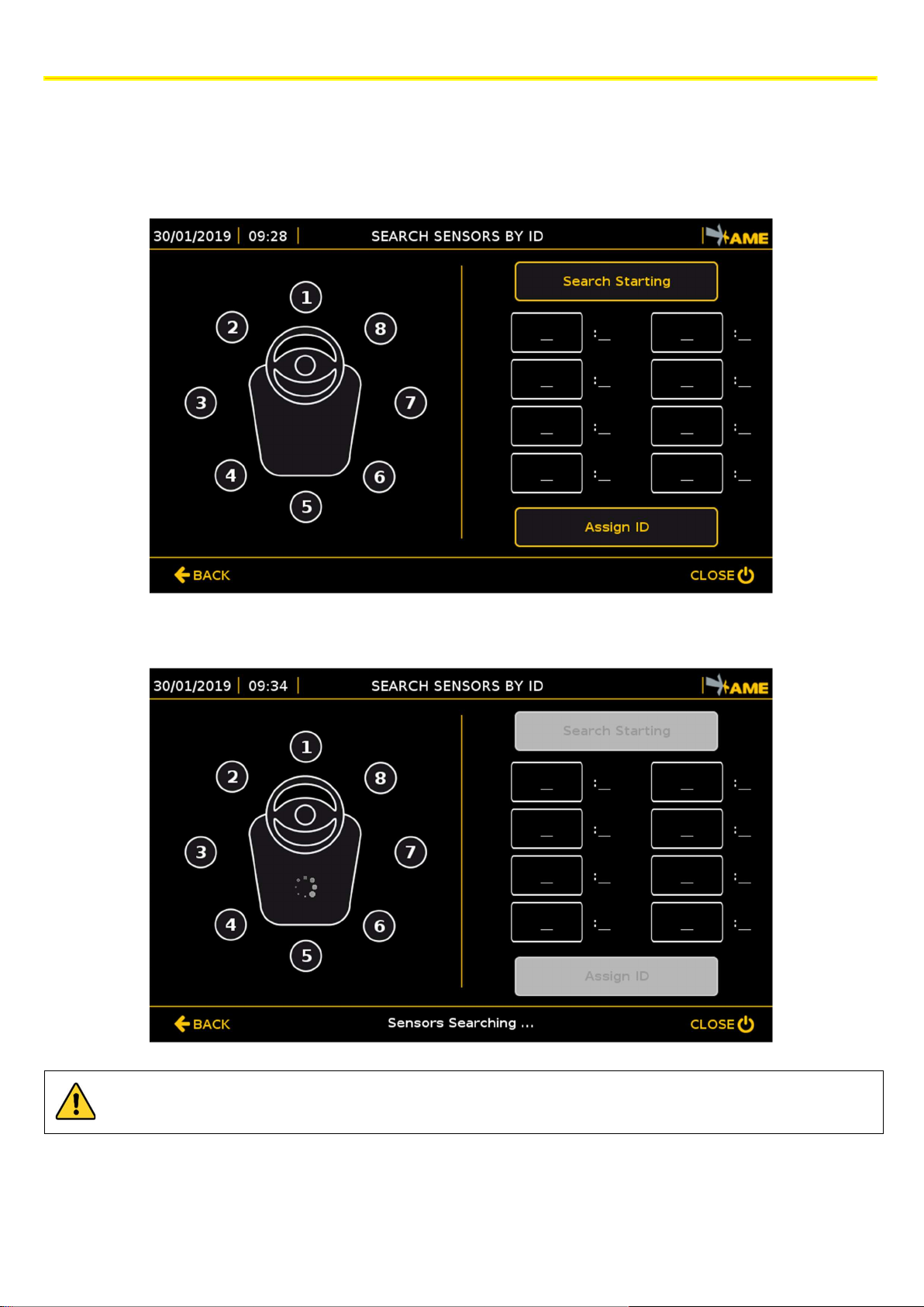
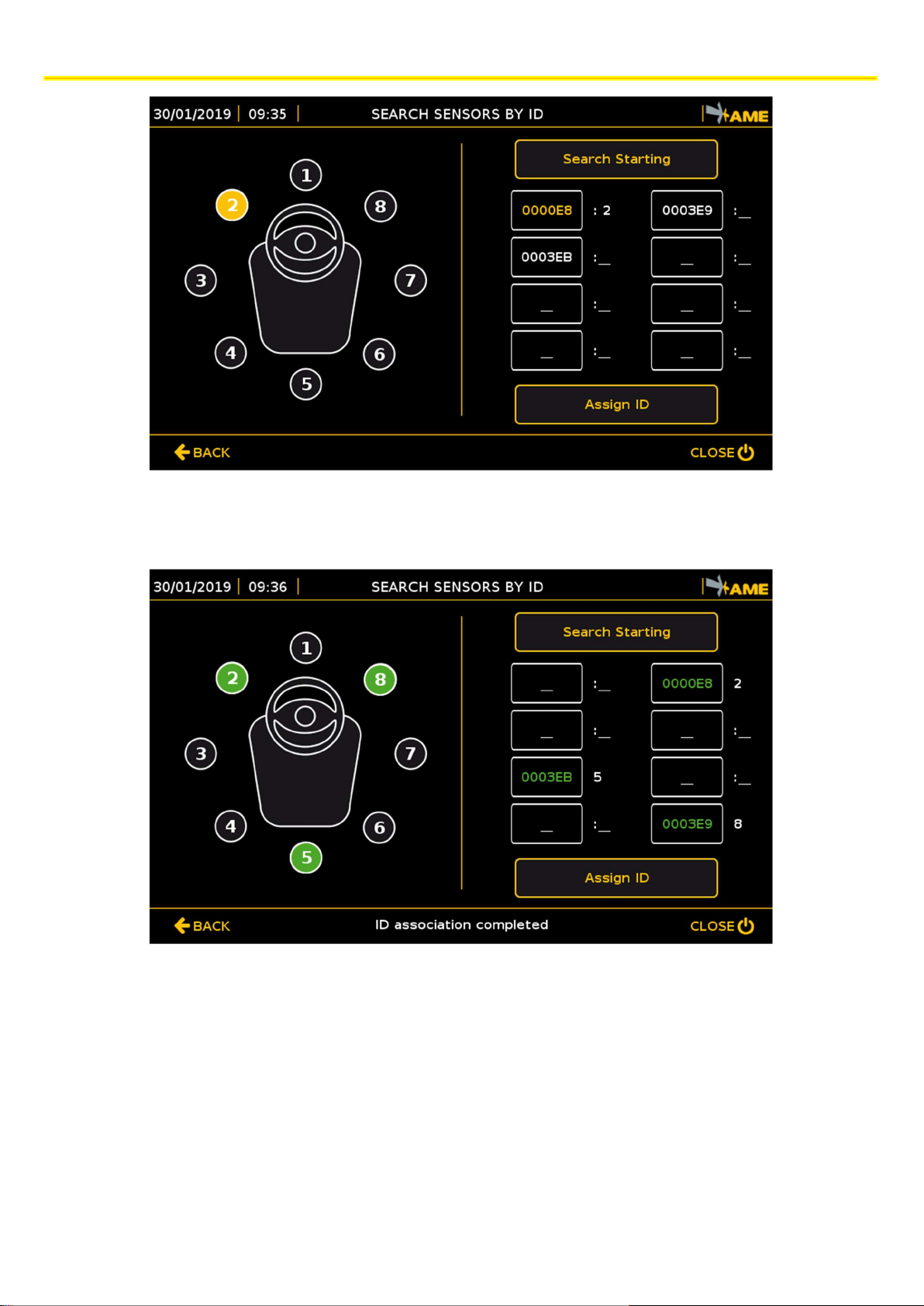
9.2.5 STEP 5 | SEARCHING SENSORS BY ID
The search sensors by ID function is used to associate each sensor ID (Factory Code uniquely assigned by the manufacturer)
with a number from 1 to 8 that identifies its position compared to the vehicle, in order to facilitate the subsequent system
calibration operations.
Press the SEARCH STARTING key to display all the sensors connected to the system.
This operation may take several seconds.
Once the Search Sensors by ID stage is completed, the sensors that have been identified are displayed.
The technical materials and information contained in this document are strictly confidential and the exclusive property of Advanced Microwave Engineering s.r.l.
These materials and information are intended solely for the purpose designated and may not be used otherwise.
It is not permitted to disclose or reproduce them in whole or in part without express written permission.
37
Page 38

TURNING-ON AND CONFIGURATION
If some sensors have not been identified, try repeating the search operation. If it still fails, check:
If no sensor is identified, check:
Position of all selectors (they must be set to 0)
Connections between sensor and HUB.
Connections between HUB and CPU
HUB power supply.
Make sure that each ID matches those that had been previously noted down, and then associate to each ID a position
identified with a number from 1 to 8.
The sensors must be positioned in the following way compared to the driver’s cabin:
FRONT SENSORS: 2 - 1 - 8
REAR SENSORS: 4 - 5 - 6
LATERAL SENSORS: 3 - 7
The following figures show, as an example, the case of the 3 sensors of the basic kit for a front counterbalanced vehicle
which must be positioned as follows:
FRONT LEFT: 2
FRONT RIGHT: 8
REAR: 5
To associate an ID to the position, press the ID to be associated (it will be highlighted in yellow, on the right side of the
screen), and then press the position (it will turn yellow, on the left side). The position associated to the ID is displayed
next to the selected ID. Proceed in the same way with the other sensors, and then press the ASSIGN ID key.
38
The technical materials and information contained in this document are strictly confidential and the exclusive property of Advanced Microwave Engineering s.r.l.
These materials and information are intended solely for the purpose designated and may not be used otherwise.
It is not permitted to disclose or reproduce them in whole or in part without express written permission.
Page 39
TURNING-ON AND CONFIGURATION
If the allocation procedure has been successful, the sensors turn green and the associated IDs move to the new positions.
In case of error, try making the allocation again.
Press BACK and return to the previous screen.
The technical materials and information contained in this document are strictly confidential and the exclusive property of Advanced Microwave Engineering s.r.l.
These materials and information are intended solely for the purpose designated and may not be used otherwise.
39
It is not permitted to disclose or reproduce them in whole or in part without express written permission.
Page 40
TURNING-ON AND CONFIGURATION
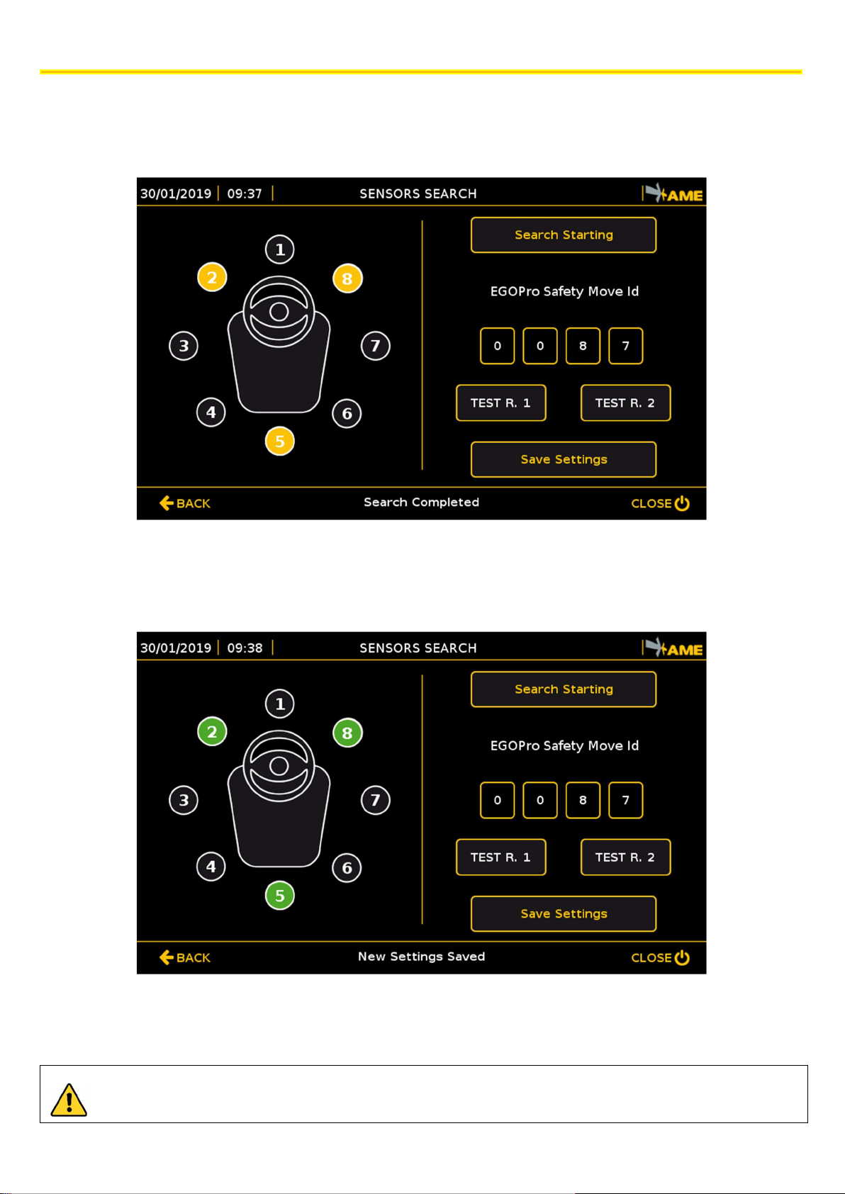
9.2.6 STEP 6 | SEARCHING SENSORS BY POSITION
This step checks the correct operation of the sensors and saves them to the system. Press SENSORS SEARCH (STEP 4
screen). The search for sensors starts automatically.
If the ID search has been correctly performed, the selected sensors (e.g. 2, 5 and 8) will turn yellow.
Press the SAVE SETTINGS key: the colour of the sensors will change from yellow to green, and, as of that moment, the
sensors will be associated to the vehicle.
Press the BACK key to return to the previous menu.
Press the BACK key to return to the main menu.
Press SEARCH STARTING to repeat the operation, for example, when the selected sensors are not highlighted
in yellow, or if - once the procedure is completed - they are not green
40
The technical materials and information contained in this document are strictly confidential and the exclusive property of Advanced Microwave Engineering s.r.l.
These materials and information are intended solely for the purpose designated and may not be used otherwise.
It is not permitted to disclose or reproduce them in whole or in part without express written permission.
Page 41
TURNING-ON AND CONFIGURATION
If the Vehicle
-
Vehicle module is active and the
white sectors are displayed indicating the presence of a vehicle
Sensor 2
Sensor 5
Sensor 8
Warning
9.2.7 SEARCHING SENSORS WITHOUT ID
A fixed position can be assigned to the sensors without making the ID search. In this case, place the selector present on
each sensor in the desired position. For example, for the basic kit:
FRONT LEFT: 2
FRONT RIGHT: 8
REAR: 5
The selector present on the HUB must be set to 0.
In this case, the SEARCH SENSORS BY ID procedure (STEP 5) must not be followed.
9.3 TEST
Once the sensors have been configured and saved to the system, make a test to check that it works correctly.
In general, the system is working correctly if the central part of the monitor is no longer red.
9.3.1 SENSOR CHECK
All sensors are in good working order if they are all green.
The Warning detection system (indicated with SR) is in good working order if the indicator on the top left corner on the
monitor is green.
Detection
but there are no other vehicles with sensors installed nearby:
Try restarting the system
Disconnect and connect again the power supply connector on the HUB
Repeat the sensors search procedure
The technical materials and information contained in this document are strictly confidential and the exclusive property of Advanced Microwave Engineering s.r.l.
These materials and information are intended solely for the purpose designated and may not be used otherwise.
It is not permitted to disclose or reproduce them in whole or in part without express written permission.
41
Page 42

TURNING-ON AND CONFIGURATION
9.3.2 TAG DETECTION TEST
Move a Tag close to each of the sensors installed and check their operation.
The transponder detection in Pre-Warning is yellow. The yellow sectors correspond to the sensor that has detected the
Tag and indicate the Tag position with respect to the vehicle.
The transponder detection in Warning is red. In this case, the TAG position with respect to the vehicle is not indicated:
there is one single indication with a red ring.
In addition to the visual alarm, there is also a sound alert.
By default, the power of sensors is set to the minimum value; therefore, the detection distances are very short.
42
The technical materials and information contained in this document are strictly confidential and the exclusive property of Advanced Microwave Engineering s.r.l.
These materials and information are intended solely for the purpose designated and may not be used otherwise.
It is not permitted to disclose or reproduce them in whole or in part without express written permission.
Page 43

OPERATION MODES
1 2
3
4
5
6
7
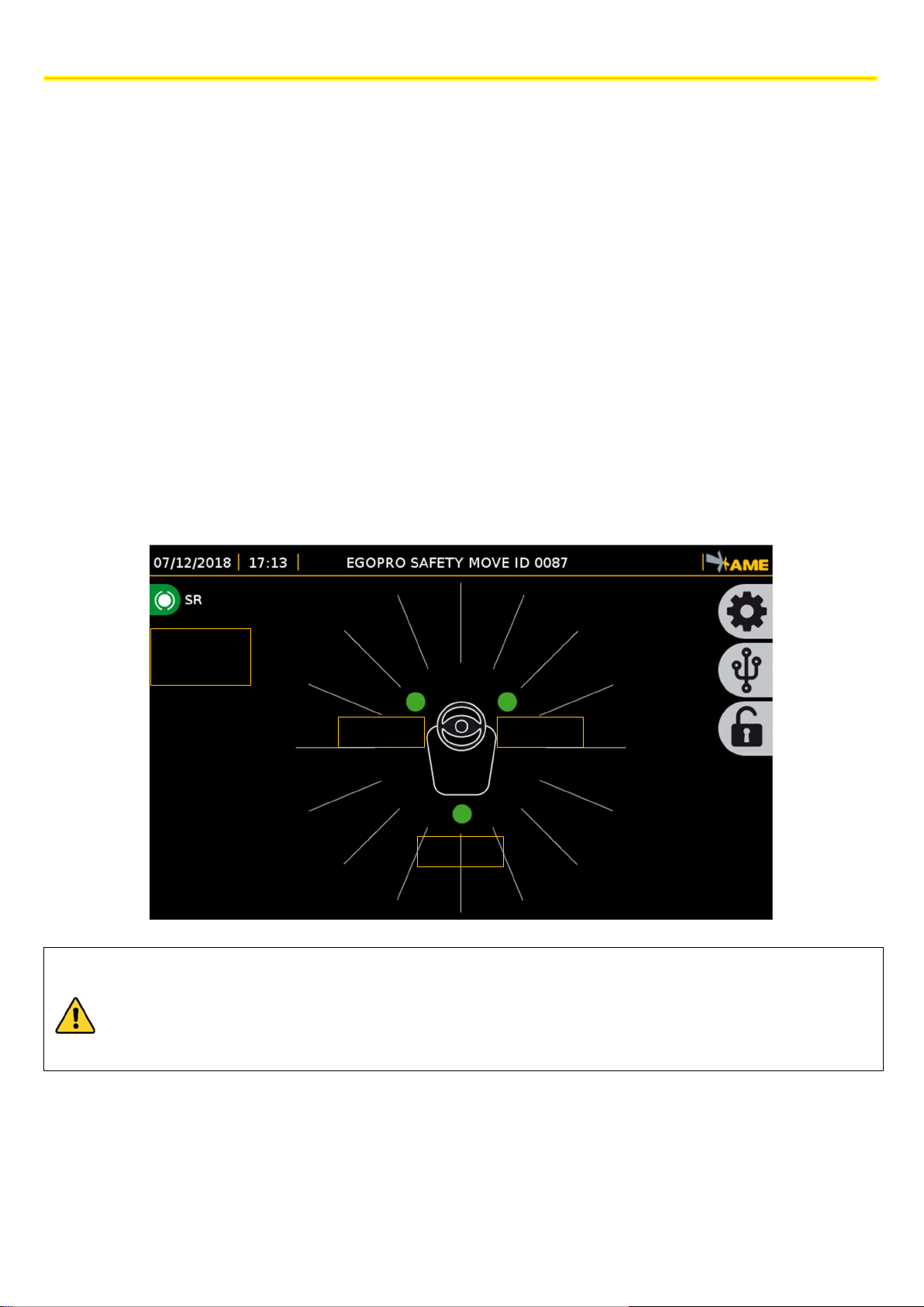
10 OPERATION MODES
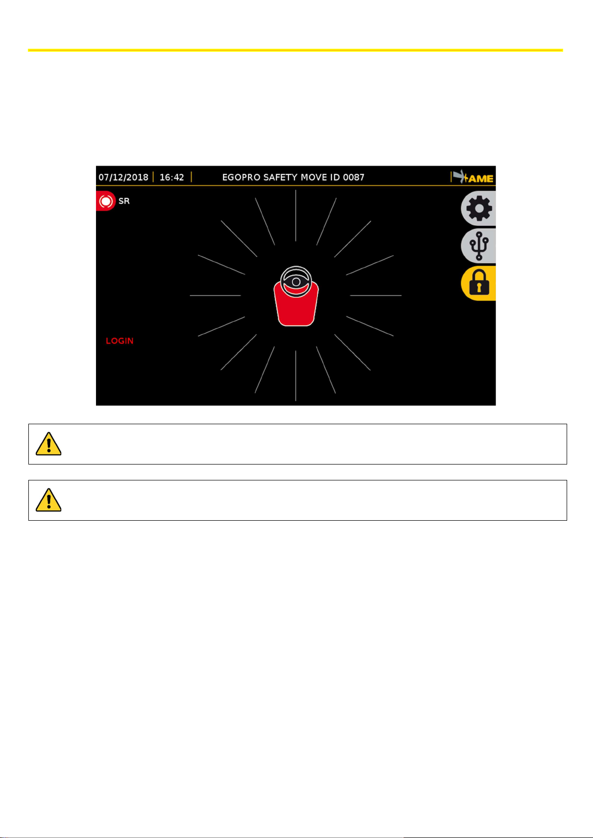
10.1 DISPLAY OVERVIEW
Main screen of EGOpro Safe MOVE 4.0 with 3 sensors installed without any detection of pedestrian workers or vehicles.
In addition, the following elements are also displayed on the screen:
1. Date and time
2. System Identification Code
3. Key to access configurations/settings
4. Key to access the section for data/log downloading
5. Key for the driver login
6. Position and status of the sensors installed. In this case, the three sensors, represented with a green circle, are
arranged as follows: two at the front and one at the rear. The green colour indicates the correct operation of
each sensor.
7. Status of the Warning detection (SR).
The technical materials and information contained in this document are strictly confidential and the exclusive property of Advanced Microwave Engineering s.r.l.
These materials and information are intended solely for the purpose designated and may not be used otherwise.
It is not permitted to disclose or reproduce them in whole or in part without express written permission.
43
Page 44

OPERATION MODES
10.2 PEDESTRIAN WORKER’S TAG DISPLAY ALARM: PRE-WARNING
The presence of the pedestrian worker wearing an active TAG within the PRE-WARNING activation range is signalled to
the driver via the display that shows the position of the pedestrian worker around the vehicle.
Lighted up sectors are associated to the sensor and they are coloured according to the sensor detecting the Tag, and so
the pedestrian worker’s position.
The sector corresponding to the pedestrian worker’s position will remain YELLOW as long as the Tag is in this area.
If several pedestrian workers are found around the vehicle simultaneously at different positions, several sectors will be
lighted up on the display corresponding to the pedestrian workers.
The visual alarm is accompanied by two sound alarms that draw the driver’s attention. The first alarm, which is loud, is
emitted when the pedestrian worker enters the PRE-WARNING area, and the second alarm, which is low, reminds that
the pedestrian worker is still within the detection area.
In addition to a visual and sound alarm on the display, the system also activatesa a relay of the CPU.
All these alarms can be configured in the ALARM CONFIGURATION section.
44
The technical materials and information contained in this document are strictly confidential and the exclusive property of Advanced Microwave Engineering s.r.l.
These materials and information are intended solely for the purpose designated and may not be used otherwise.
It is not permitted to disclose or reproduce them in whole or in part without express written permission.
Page 45

10.3 PEDESTRIAN WORKER’S TAG DISPLAY ALARM: WARNING
OPERATION MODES
The presence of the pedestrian worker wearing an active TAG within the WARNING activation range is signalled to the
driver via the display by means of a clearly visible red ring.
The PRE-WARNING alarm indication remains visible and helps the driver locate the personnel on foot.
The red ring will remain lit up, together with the two lateral LEDs in the display, as long as the Tag is in this area.
The visual alarm is accompanied by two sound alarms that draw the driver’s attention. The first alarm, which is loud, is
emitted when the pedestrian worker enters the WARNING area, and the second alarm, which is low, reminds that the
pedestrian worker is still within the detection area.
In addition to a visual and sound alarm on the display, the system also activates a second relay of the CPU and two relays
present on the HUB.
All these alarms can be configured in the ALARM CONFIGURATION section.
The technical materials and information contained in this document are strictly confidential and the exclusive property of Advanced Microwave Engineering s.r.l.
These materials and information are intended solely for the purpose designated and may not be used otherwise.
It is not permitted to disclose or reproduce them in whole or in part without express written permission.
45
Page 46

OPERATION MODES
The
self-diagnosis system does not allow identifying all the possible anomalies of the system. For example, it
10.4 SENSORS AND HUB DIAGNOSIS
Active sensors are displayed matching their position on the vehicle. Only fitted and configured sensors are shown on the
display.
The system is equipped with a self-diagnosis function that constantly checks the correct operation of the devices. If the
icon of the sensor is GREEN, it means that the diagnosis system did not detect any anomalies on that specific sensor.
The system signals any anomalies by illuminating the seat and the icon of the sensor that is not working in red. Moreover,
the type of error detected by the system is shown for 5 seconds at the bottom left-side corner.
A sound warning is reproduced together with the visual alarm.
The error message can also be subsequently displayed by pressing the red icon corresponding to the sensor in alarm.
The anomalies that can be detected during self-diagnosis are the following:
Communication Error: no communication between CPU and HUB and/or HUB and sensor.
Microwave Error: the sensor may not be able to activate the Tag in pre-warning mode (yellow) and be detected
by other vehicles.
Low Frequency Error: the sensor may not be able to activate the Tag in warning mode (red).
RF Sensor Error: the sensor may not be able to detect the presence of other vehicles.
Radio Frequency Error: the HUB may not be able to receive the activation of the Tags.
does not detect whether the RF antenna of the HUB and/or one or several internal antennas of a sensor are
not connected, as it may happen after one of the components of the system undergoes a strong impact.
It is therefore advisable to thoroughly check the system on a regular basis following the procedure specified
in the maintenance section (chapter 23).
46
The technical materials and information contained in this document are strictly confidential and the exclusive property of Advanced Microwave Engineering s.r.l.
These materials and information are intended solely for the purpose designated and may not be used otherwise.
It is not permitted to disclose or reproduce them in whole or in part without express written permission.
Page 47

10.5 DRIVER LOGIN
Press the yellow login icon
- a closed padlock
- to login, and enter your driver’s code/T
ag code. Once the login is
The LOGOUT
operation is essential to be able to make the driver’s Tag visible again for the anti
-
collision
OPERATION MODES
The LOGIN operation is used to check which operator is driving the vehicle at the date and time requested, and it is
essential to exclude the driver’s TAG from the anti-collision system.
When the system is turned on, the main interface presents a lateral red message inviting the user to LOGIN, which is
signalled by a yellow icon.
complete, the icon will become grey, the symbol will turn into an open padlock, and the login word in red will
disappear.
For the LOGOUT operation, press again the grey icon and it will be yellow again.
system.
When the system is turned off, the LOGOUT operation is automatically performed.
The technical materials and information contained in this document are strictly confidential and the exclusive property of Advanced Microwave Engineering s.r.l.
These materials and information are intended solely for the purpose designated and may not be used otherwise.
It is not permitted to disclose or reproduce them in whole or in part without express written permission.
47
Page 48
OPERATION MODES
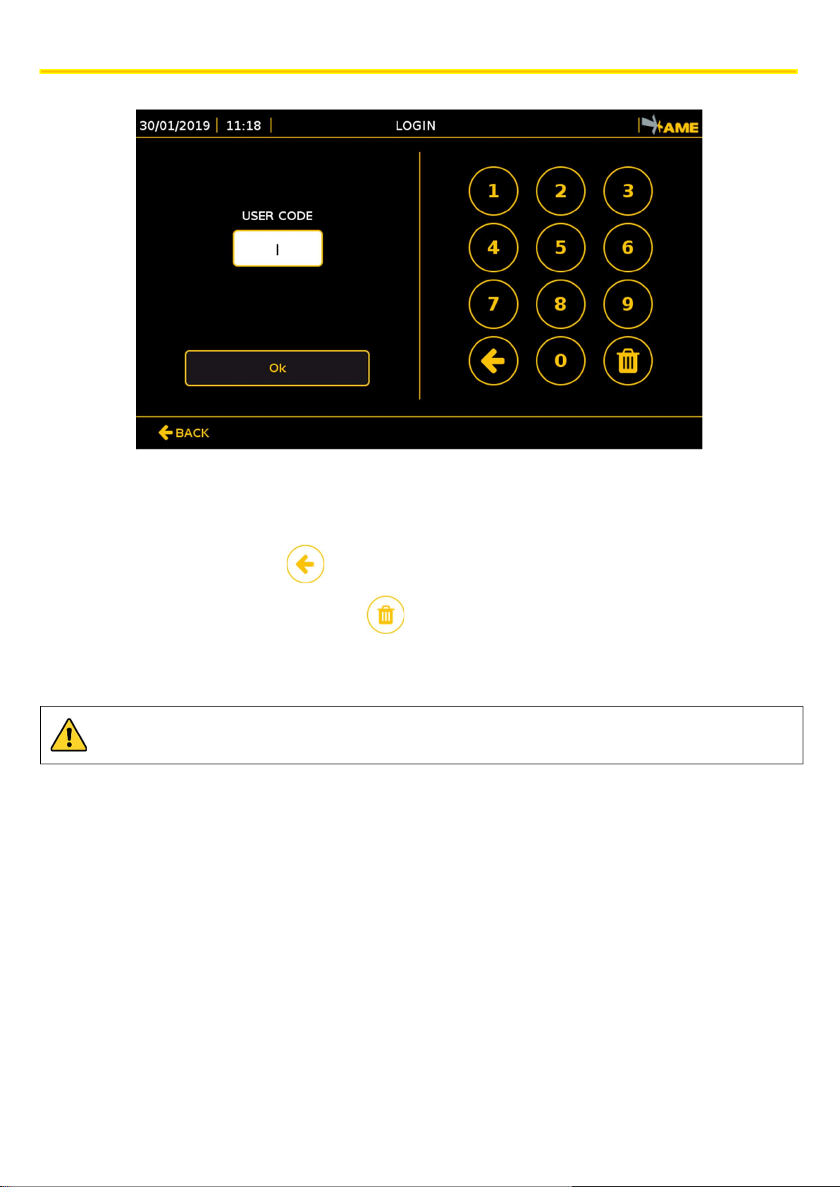
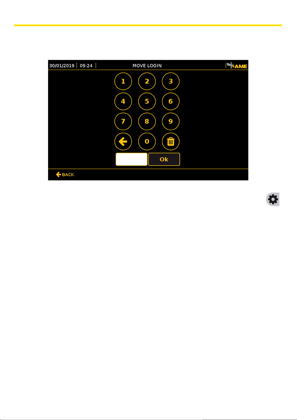
For the login operation, enter the unequivocal ID in the space:
USERCODE: unequivocal numerical code of 6 figures: the code usually coincides with the TAG own code.
Use the numerical keyboard to enter the code.
To delete only one character:
To delete all characters together:
Once the code has been entered, press OK. The system automatically returns to the main screen.
In order to log in, the list of users must have been added to the system (see section 11.8).
48
The technical materials and information contained in this document are strictly confidential and the exclusive property of Advanced Microwave Engineering s.r.l.
These materials and information are intended solely for the purpose designated and may not be used otherwise.
It is not permitted to disclose or reproduce them in whole or in part without express written permission.
Page 49
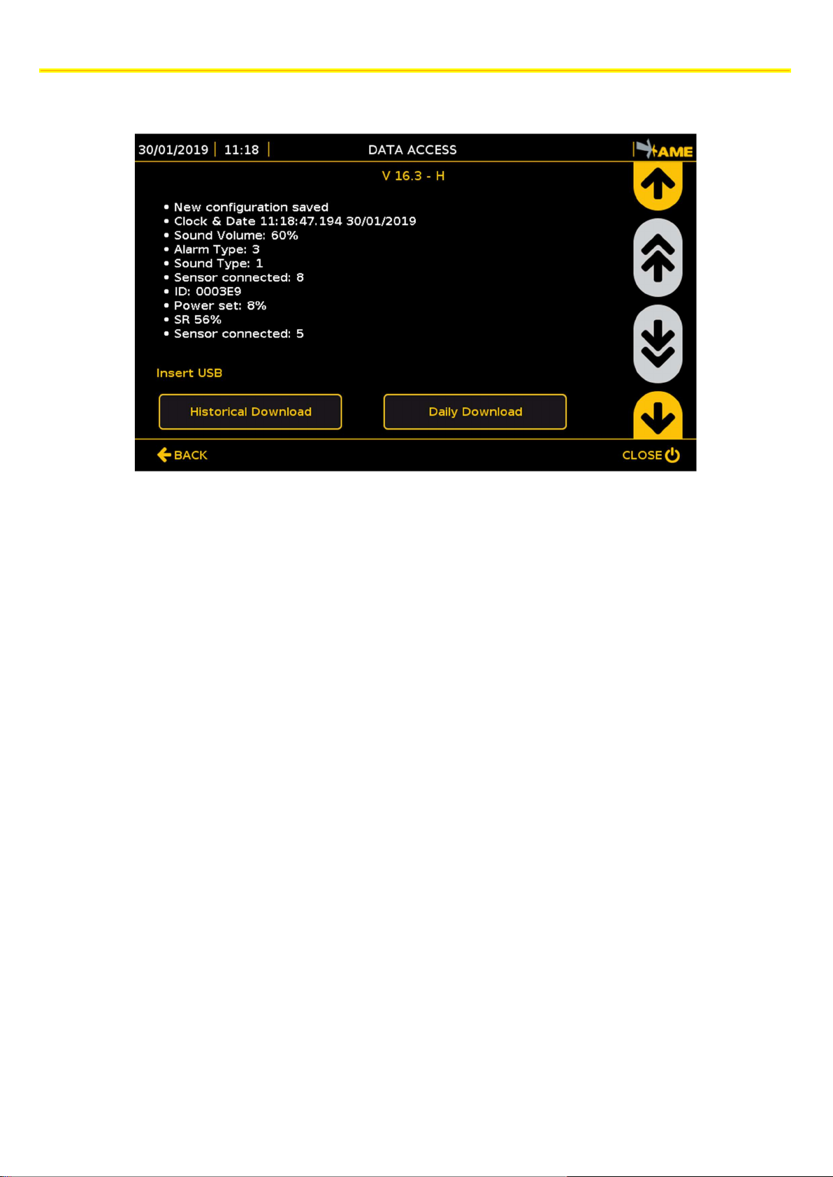
10.6 DATA ACCESS
OPERATION MODES
Press the key with the USB icon and enter the relevant password to access the data page in which the history of events
is shown.
Up to 1,000 events can be displayed, including:
• TAGS detected with the following information: detected TAG code - activated sensor - date and time - position
(if the GPS module is enabled)
• Configurations carried out: type of configuration and saved data.
• Shocks (if the shocks module is enabled) with the following information: date and time - GPS coordinates (if
the option is installed) - shock intensity.
Use the side arrows to scroll the list of information.
Moreover, in this section, once a USB is inserted into the specific input of the CPU, data can be downloaded by using the
following keys:
Daily download: the daily events are downloaded to the USB.
Historical download: the events of the previous 60 days are downloaded to the USB. Any data older than 60 days is
automatically deleted from the system.
The technical materials and information contained in this document are strictly confidential and the exclusive property of Advanced Microwave Engineering s.r.l.
These materials and information are intended solely for the purpose designated and may not be used otherwise.
It is not permitted to disclose or reproduce them in whole or in part without express written permission.
49
Page 50
BASIC CONFIGURATION
11 BASIC CONFIGURATION
11.1 ACCESS TO MENU
Press the CONFIGURATION icon to access the menu
To access the system configuration section, a password must be entered so that only the enabled user can view this
screen.
The default password is 1234.
50
The technical materials and information contained in this document are strictly confidential and the exclusive property of Advanced Microwave Engineering s.r.l.
These materials and information are intended solely for the purpose designated and may not be used otherwise.
It is not permitted to disclose or reproduce them in whole or in part without express written permission.
Page 51

11.2 REBOOT
To reboot or stop the system, enter the specific password and open the configuration menu.
CLOSE key to reboot the system. If necessary, press this key to reboot the system. This key is shown in all the
configuration screens
BASIC CONFIGURATION
If the system is turned off, you will need to disconnect and reconnect power to restart it.
The technical materials and information contained in this document are strictly confidential and the exclusive property of Advanced Microwave Engineering s.r.l.
These materials and information are intended solely for the purpose designated and may not be used otherwise.
It is not permitted to disclose or reproduce them in whole or in part without express written permission.
51
Page 52
BASIC CONFIGURATION
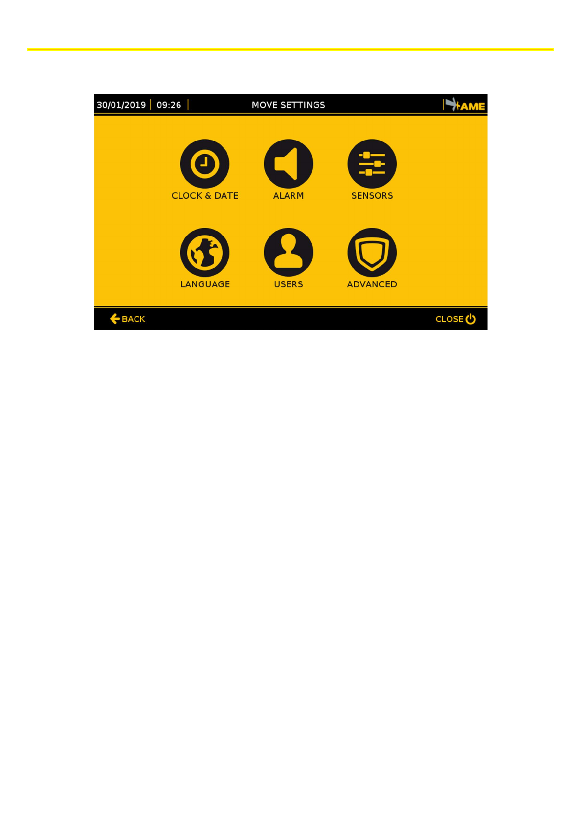
11.3 CONFIGURATION MENU
In the configuration menu, you can:
Set the system Time and Date
Configure the Modes of the alarms
Configure the sensors (System Calibration)
Select the language preferred
Set the master data of users/drivers
ADVANCED configurations: only authorised installers can have access to them.
Press the dedicated key to select the function.
52
The technical materials and information contained in this document are strictly confidential and the exclusive property of Advanced Microwave Engineering s.r.l.
These materials and information are intended solely for the purpose designated and may not be used otherwise.
It is not permitted to disclose or reproduce them in whole or in part without express written permission.
 Loading...