

ADVANCED LINEAR DEVICES EH300, EH300A, EH301, EH301A Service Manual

A
DVANCED
L
INEAR
D
EVICES, INC.
EH300/EH300A/EH301/EH301A
EH300/EH301 EPAD® ENERGY HARVESTINGTM Modules
GENERAL DESCRIPTION
EH300/EH301 Series EPAD® ENERGY HARVESTING
TM
Modules can accept energy from many types of electrical
energy sources and store this energy to power conventional
3.3V and 5.0V electrical circuits and systems. EH300/EH301
Series Modules are completely self-powered and always in
the active mode. They are intended for low power intermittent duty cycle sampled data or condition-based monitoring/
extreme lifespan applications. These Modules can work with
instantaneous input voltages ranging from 0.0V to +/-500V
AC or DC, and input currents from 200nA to 400mA from
energy harvesting sources that produce electrical energy in
either a steady or an intermittent and irregular manner with
varying source impedances. EH300/EH301 Series Modules
condition the stored energy to provide power at output voltage and current levels that are within the limits of a particular electronic system power supply specifications. For example, 1.8V and 3.6V is a useful voltage range for many
types of I.C. circuits such as microprocessors.
EH300/EH301 Series Modules are designed to continuously
and actively operate to capture, accumulate and conserve
energy from an external energy source. Each individual
EH300/EH301 Series Module is set to operate between two
supply voltage thresholds, +V_low DC and +V_high DC,
corresponding to the minimum (VL) and maximum (VH) supply voltage values for the intended application. When an energy source starts to inject energy into the inputs of an EH300/
EH301 Series Module in the form of electrical charge impulses, these charge packets are collected, accumulated and
stored onto an internal storage capacitor bank. For most common energy harvesting applications, the electrical energy
charge packets arrives in the form of input voltage spikes
that are uncontrolled and unpredictable. Often these cover
a wide range of voltages, currents and timing waveforms.
EH300/EH301 Series Modules are designed to accommodate such conditions with exceptional efficiency and effectiveness. As an example, EH300 Series Module can cycle
within 4 minutes at an average input current of 10 µA and
within 40 minutes at an average input current of just 1.0 µA.
SPECIFICATIONS
EH300/EH300A/EH301/EH301A
Input/Output Electrical Specifications @25° C
• Max. Instantaneous Input Voltage: +/- 500V
• Max. Instantaneous Input Current: 400mA
• Max. Input Power: 500mW
• Min. Operational Input: 0.0V@1nA
• Min. Charging Input (Max. Power Dissipation):
- EH300 4.0V@200nA(800nW)
- EH301 6.0V@300nA(1800nW)
- EH300A 4.0V@500nA(2µW)
- EH301A 6.0V@500nA(3µW)
• Internal Voltage Clamp: 7.0V@10mA
• Max. Output Current: 1 amp
• Operating Life Cycles: Virtually unlimited
• Logic Compatibility: CMOS
EH300
•VL=1.8V VH=3.6V
• Useful Energy Output@ 4.6mJ
• Output On-Time Rating: 68msec@25mA
EH300A
•VL=1.8V VH=3.6V
• Useful Energy Output@ 30mJ
• Output On-Time Rating: 75msec@150mA
EH301
•VL=3.1V VH=5.2V
• Useful Energy Output@ 8.3mJ
• Output On-Time Rating: 80msec@25mA
EH301A
•VL=3.1V VH=5.2V
• Useful Energy Output@ 55mJ
• Output On-Time Rating: 88msec@150mA
ORDERING INFORMATION
FUNCTIONAL DESCRIPTION
Part Number Description
EH300/EH301 Series Modules' voltage on the
EH300 4.6 mJ Module / 1.8V to 3.6V operation
EH300A 30 mJ Module / 1.8V to 3.6V operation
onboard storage capacitor bank is +V, which is also the
positive supply voltage switched to power the output
power load. Initially, +V voltage on an EH300/EH301
EH301 8.3 mJ Module / 3.1V to 5.2V operation
EH301A 55 mJ Module / 3.1V to 5.2V operation
Series Module starts at 0.0V. During the initial charge
period, +V starts charging from 0.0V . The internal circuit
of the Module monitors and detects this +V voltage. When
EHJ1C 6 inch cable / J1connector (Input)
EHJ2C 6 inch cable / J2 connector (Output)
Note: EH300A and EH301A are high energy output versions
© 2007 Advanced Linear Devices, Inc. 415 Tasman Drive, Sunnyvale, California 94089 -1706 T el: (408) 747-1 155 Fax: (408) 747-1286 http://www .aldinc.com
+V reaches VH, the Module output (VP) is enabled and
turned to the ON state and is then able to supply power
to a power load, such as a microprocessor and/or a sensor
+Input
-Input
Ground
V
P
(Output)
Energy
Source
GND
+
V
Application
Module
circuit. The amount of useful energy available is a function
of the capacity of the storage capacitor bank. Meanwhile,
an EH300/EH301 Series Module continue to accumulate
any energy generated by external energy sources. If external energy input availability is high, output VP remains in an
ON state continuously, until such time that external energy
availability is lower than the power demand required by the
power load. As external energy input exceeds power loading, +V increases until internal voltage clamp circuits limit it
to a maximum clamp voltage.
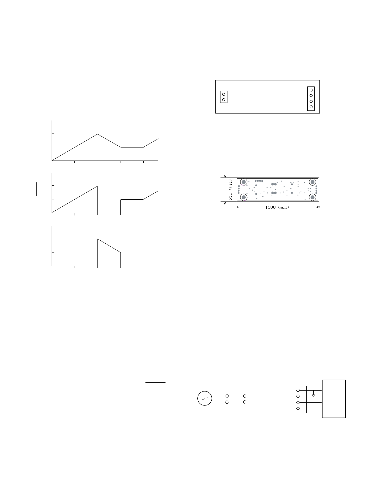
EH300/EH301 Waveforms
+
V
V
H
V
L
Mechanical Specifications
• Outline Dimensions:
W x L x H : 0.55 in. x 2.00 in. x 0.70 in.
• 4 Mounting Holes: 0.085 in. diameter
• Weight: 0.5 ounce (14 grams) nominal
EH300/EH301 Top View
J1
+Input
-Input
Socket Adapter Cable:
J1: Hirose Socket, 2 Position P/N : DF13-2S
J2: Hirose Socket, 4 Position P/N : DF13-4S
Ground
V
R (Ready)
V
P (Output)
+V
J2
t
V
R
V
H
READY
V
L
V
P
V
H
OUTPUT
V
L
1
t
1
t
1
t
2
t
2
t
2
t
3
t
3
t
3
t
4
t
4
t
4
During normal operation, as power is drawn from an EH300/
EH301 Series Module, +V decreases in voltage. When +V
reaches VL, output VP switches to an OFF state and stops
supplying any further power to the power load. With built-in
hysteresis circuits within the Module, VP now remains in the
OFF state even when the external energy source starts
charging the capacitor bank again by importing fresh new
impulses of electrical energy . Once VH level is reached again,
output VP is then turned to the ON state again. Hence +V
voltage cycles between VH to VL voltage levels and then to
the OFF state. When in the ON state, VP can supply up to
1A of current for a limited time period as determined by the
stored useful energy and the energy demand by the power
load. An optional input/ouput pin VR functions as VP on/off
control (external input through 1KOhm) or as READY logical control (output) signal preceeding output VP switching.
Module Dimensions
Environmental Specifications
• Leadfree (ROHS) compliant
• Operating Temperature Range: 0 to 70° C
• Max. Average Operating Temperature : 50° C
• Storage Temperature: -40 to +85° C
• Humidity: To 90% (no condensation)
• Protection: Conformal and Epoxy coated
Initial Setup & Calibration
EH300/EH301 Series Modules are setup and calibrated at
the factory to standard specifications and settings. No user
setup is required. Optional user control signal and connection to external capacitor or battery storage banks are available at the output port. All EH300/EH301 Series Modules
are shipped Ready to Use.
EH300/EH301 Typical Application
Input energy charging times t1 and t2 are limited by input
energy available minus energy loss by an EH300/EH301
Series Module. The energy output time period t3 is determined by the rate of energy used by the power load as a
function of energy stored. Low input energy hold time t4 is
typically many orders of magnitude greater than the sum of
t1, t2 and t3.
Advanced Linear Devices EH300/EH301
 Loading...