

Page 1

The Advanced® Osmometer
Model 3900
User’s Guide
3905 Rev20 061213
Page 2

Copyright
This user’s guide is copyrighted by Advanced Instruments, Inc. with all
rights reserved. Under copyright laws, this guide may not be reproduced
in any form, in whole or part, without the prior written consent of
Advanced Instruments.
© 2003 Advanced Instruments, Inc.
Windows
®
is a registered trademark of Microsoft Corporation in the
United States and other countries. All other trademarks are the property of
Advanced Instruments, Inc.
Advanced Instruments has reviewed this guide thoroughly. All material
contained within is believed reliable, but the accuracy and completeness
are not guaranteed or warranted, and are not intended to be representations
or warranties concerning the product described.
Hot-Line®Service
If you have any questions or problems regarding the proper operation of
your instrument, please contact our Hot-Line Service department:
• 800-225-4034 (toll-free within the USA and Canada; after normal busi-
ness hours, dial extension 2191)
• +US 781-320-9000 (elsewhere)
• 781-320-0811 (fax)
ii
The Advanced®Osmometer Model 3900 User’s Guide
Page 3

Table of Contents
Parts & Accessories v
Calibrators & Standards vii
Safe Use ix
Symbol conventions ix
General cautions x
Foreword: Theory and Technique xiii
Intended Use xiii
Principles of Freezing-Point Osmometry xiv
Instrumentation xv
Freezing-Point Thermodynamics xv
Definitions xvi
Chapter 1 — Installation & Setup 1
Step 1 — Find a location for your instrument 1
Step 2 — Unpack your instrument 2
Step 3 — Setup and installation 3
Step 4 — Load printer paper 7
Step 5 — Obtain additional items 9
Step 6 — Power up your instrument 9
Step 7 — Install heat transfer fluid 10
Step 8 — Run self-diagnostic test 12
Step 9 — Proceed to instrument operation 12
Chapter 2 — Instrument Operation 13
Hazardous material cautions 13
Function of major components 14
Bar code scanner 18
Setup 20
iii
Page 4

Operating instructions 30
Sample test procedure 32
Testing batch-numbered or bar code-scanned samples 38
Repeatability tips 40
Stat tests 41
Recall 42
Chapter 3 — Standards & Quality Control 43
Repeatability and accuracy 43
Standards and controls 43
Maintenance of standards 44
Quality control implementation 45
Chapter 4 — Calibration 47
Calibration procedure 47
Calibration notes 48
Chapter 5 — Troubleshooting & Service 51
Service & maintenance cautions 51
Obtaining service 53
Routine maintenance 55
Shutdown and storage 56
Troubleshooting 56
Test 57
Adjustment and replacement of parts and assemblies 67
Appendices 79
Appendix A: Troubleshooting Table 79
Appendix B: Product Specifications 91
Appendix C: Regulatory Notices 93
Appendix D: Warranty and Warranty Duties 97
Appendix E: Supplemental RS-232 Information 101
Appendix F: Symbol Definitions 103
Appendix G: Product Disposal and Recycling 107
Appendix H: Service Log 109
Index 111
iv
The Advanced®Osmometer Model 3900 User’s Guide
Page 5

Parts & Accessories
v
To order parts and accessories, contact the Advanced
Instruments Customer Service Department:
• 800-225-4034 (toll-free within the USA and Canada)
• +US 781-320-9000 (elsewhere)
• 781-320-3669 (fax)
PART DESCRIPTION
Calibration Cassette
Disposable Sample Tubes, 0.2 to 0.3-mL, one pkg. of 500
Sample Tube Cassettes, #1-5
Sample Tube Cassettes, #6-10
Sample Tube Cassettes, #11-15
Sample Tube Rack
Heat Transfer Fluid, one 160-mL bottle
Cooling Reservoir Fill Funnel
Thermal Printer Paper, one pkg of 5
Evaporation Cover
Fluid Fill Plug (vented)
PART NO.
4C3040
3LA825
4C3050
4C3060
4C3070
3LA846
3DA811
4C3308
FLA835
390330
4C3448
Page 6

vi
PART DESCRIPTION
Paper Roll Holder
Printer Maintenance Kit with Instructions
Box of 100 Probe Wipers, one pkg of 100
10-Pack Drip Return Wipers, one pkg of 10
Disposable Air Filters, one pkg of 6
Operator/supervisor Keys, two
Power Cord (specify voltage and country)
Stir/Freeze Wire, two
Replacement Sample Probe with three 10-mL ampules of
Probe Bin-Setting Fluid
Probe/Stir Alignment Kit
Mandrel
Clapper Replacement Assembly
Yoke
Stir/Freeze Coil
Serial Port Computer Cable with DB9S:
3-Meter Shielded RS-232
6-Meter Shielded RS-232
9-Meter Shielded RS-232
3900 User’s Guide
3900 Service Manual
Bar Code Reader with Stand and Instructions, one kit
PART NO.
FL0408
FL0425
4C3840
3D2340
3D3185
3C2243
4C3700
3LA700
390444
3C2241R
3LH230
3D2404
330053
330056
330059
3905
3905SM
390016
The Advanced®Osmometer Model 3900 User’s Guide
Page 7

vii
Calibrators & Standards
To order parts and accessories, contact the Advanced
Instruments Customer Service Department:
• 800-225-4034 (toll-free within the USA and Canada)
• +US 781-320-9000 (elsewhere)
• 781-320-3669 (fax)
PART DESCRIPTION
Clinitrol™290 Reference Solution, ten 5-mL ampules
Protinol®3-level Protein Control Kit, nine (3 ea) 3-mL
vials
Renol™ Urine Osmolality Controls (2 levels)
Five-Level Osmolality Linearity Set: 100, 500, 900, 1500,
and 2000 mOsm/kg; ten (2 ea) 5-mL ampules
100 mOsm/kg Calibration Standard, ten 5-mL ampules
500 mOsm/kg Calibration Standard, ten 5-mL ampules
900 mOsm/kg Calibration Standard, ten 5-mL ampules
1500 mOsm/kg Calibration Standard, ten 5-mL ampules
3000 mOsm/kg Calibration Standard, ten 5-mL ampules
100 mOsm/kg Calibration Standard, one 110-mL bottle
500 mOsm/kg Calibration Standard, one 110-mL bottle
900 mOsm/kg Calibration Standard, one 110-mL bottle
1500 mOsm/kg Calibration Standard, one 110-mL bottle
PART NO.
3LA029
3MA028
3LA085
3LA028
3LA011
3LA051
3LA091
3LA151
3LA301
3LA010
3LA050
3LA090
3LA150
Page 8

viii
NOTE Advanced Instruments, Inc. cannot guarantee the stated instru-
ment performance specifications and accuracy of test results
unless Advanced Instruments brand consumables are used with
the instrument. Use of consumables from manufacturers other
than Advanced Instruments is not recommended and may
adversely affect system calibration, performance, operation,
and accuracy of test results. For information on obtaining these
standards and controls, contact Advanced Instruments or an
authorized representative.
The Advanced®Osmometer Model 3900 User’s Guide
Page 9

Safe Use
To reduce the risk of bodily injury, electric shock, fire, and
damage to your instrument, please read and observe the precautions in this User’s Guide.
• If the product is used in a manner not in accordance with the
equipment design, operating instructions or manufacturer's
recommendations, the operation of the product may be
impaired to the extent that a safety hazard is created.
• Do not attempt to perform electrical work if you are not
fully qualified. This manual is not a substitute for electrical
training.
Symbol conventions
The exclamation point within an equilateral triangle is
intended to alert the user to the presence of important
operating and maintenance (servicing) instructions in
the literature accompanying this product.
The lightning flash with arrowhead symbol within an
equilateral triangle is intended to alert the user to the
presence of uninsulated dangerous voltage within the
product's enclosure that may be of sufficient magnitude
to constitute risk of electric shock to persons.
The static symbol within an equilateral triangle is
intended to alert the user to the presence of internal
components that could be damaged by static electricity.
ix
Page 10

This static symbol is intended to alert the user to the presence
of a specific component that could be damaged by static electricity.
This symbol indicates the presence of alternating current (AC).
This symbol indicates the presence of a fuse.
This symbol indicates the presence of protective earth ground.
General cautions
• This product should be operated only with the type of power source
indicated on the product’s electrical ratings label. Refer to the installation instructions included with the product.
• If the power cord provided is replaced for any reason or if an alternate cord is used, the cord must be approved for use in the local
country. The power cord must be approved for the product’s listed
operating voltage and be rated at least 20% greater than the ampere
ratings marked on the product’s electrical ratings label. The cord
end that connects to the product must have an IEC 60320 connector.
• Plug the product into an approved grounded electrical outlet.
• Do not disable the power cord’s grounding plug.
• If an extension cord or power strip is used, make sure that the cord
or strip is rated for the product, and that the total ampere ratings of
all products plugged into the extension cord or strip do not exceed
80% of the cord’s or strip’s rating limit.
• Route power cords so that they will not be walked on, tripped on, or
pinched by items placed upon or against them. Pay particular attention to the plug, electrical outlet, and the point where the cord exits
the product.
x
The Advanced®Osmometer Model 3900 User’s Guide
Page 11

• Do not pull on cords and cables. When unplugging cords or cables,
grasp the corresponding connector.
• Do not install or use this product in any area subject to extreme
short-term temperature variations, or locations that exceed the specified operating environment temperatures.
• Never use this product in a wet area.
• To avoid injury or fire hazard, do not operate this product in an
explosive atmosphere.
• Do not install or use the product on an unstable, non-level work surface.
• Do not operate this product with the covers removed or unsecured.
xi
Safe Use
Page 12

xii
The Advanced®Osmometer Model 3900 User’s Guide
Notes:
Page 13

Foreword
xiii
Intended Use
Advanced®Osmometers use the technique of freezing-point
depression to measure osmolality. Osmolality is the total solute
concentration of an aqueous solution. Osmometers measure the
number of solute particles irrespective of molecular weight or
ionic charge. This information is useful to the following disciplines:
Clinical, emergency and sports medicine
Medical research
Biotechnology and pharmaceutical research and
manufacturing
Food and beverage manufacturing
Environmental research and monitoring
Academic research
Industrial applications
When used by a trained operator in clinical applications, the
osmometer provides results that assist in establishing the proper
diagnoses and treatments for patients with disorders involving
water and electrolyte imbalances. Osmometers will test virtually any biological fluid including, but not limited to, whole
blood, plasma, urine, feces, sweat, and tissue homogenate.
Operation of the instrument is deemed to be low-complexity
under CLIA and FDA guidelines.
Page 14

xiv
The Advanced®Osmometer Model 3900 User’s Guide
Principles of Freezing-Point Osmometry
When a solute is dissolved in a pure solvent, the following changes in
the solution's properties occur:
• the freezing point is depressed,
• boiling point is raised,
• osmotic pressure is increased, and
• vapor pressure is lowered.
These are the so-called "colligative" or concentrative properties of the
solution which, within reasonable limits, change in direct proportion to
the solute concentration; in other words, the number of particles in
solution.
Of the colligative properties, measurement of the freezing point allows
the concentration of an aqueous solution to be easily determined with
great precision.
The freezing point of pure H
2
O is precisely +0.010°C. One mole of a
non-dissociating solute such as glucose (where the solute does not dissociate into ionic species, but remains intact), when dissolved in 1 kilogram (kg) of water will depress the freezing point by 1.858°C. This
change is known as the freezing point depression constant for water.
The freezing point depression also depends upon the degree of dissociation of the solute. If the solute is ionic, the freezing point is
depressed by 1.858°C for each ionic species. For example, if one mole
of sodium chloride were to completely dissociate into two ionic species
(Na+ and Cl-) in 1 kg of water, the freezing point would be depressed
by 3.716°C. However, dissociation is never complete. Interference
between solute molecules reduces dissociation by a factor called the
osmotic coefficient.
Page 15

xv
Foreword
In a simple solution such as glucose or sodium chloride in water, the
freezing point can be measured and the unit concentration easily determined from an equation or a reference table. However, the equation is
unique for each solute. In a more complex solution, all ionized and
non-dissociated species contribute to the freezing-point depression and
the concentration of each solute cannot be easily determined.
Each of the colligative properties has a similar problem, and though
each of the colligative properties changes in direct proportion to the
solute concentration, each requires a different mode & unit of measurement. Osmolality is a common unit of concentration measurement that
can be used to relate all the colligative properties to each other, and to
other concentration units. Because of its universality, most osmometry
applications regularly use osmolality, expressed as "mOsm/kg H
2
O", as
the common unit of concentration rather than applying further conversion factors.
Instrumentation
Advanced Osmometers are devices for the determination of the concentration of solutions by means of freezing-point measurement.
Advanced Osmometers utilize high-precision thermistors to sense the
sample temperature, to control the degree of supercooling and freeze
induction, and to measure the freezing point of the sample. They can
routinely determine differences of ±1 mOsm/kg H
2
O.
Freezing-Point Thermodynamics
The quickest and most precise way to measure the freezing point of a
solution is to supercool it several degrees below its freezing point. It is
unstable in this state, and a mechanical agitation induces crystallization.
The heat of fusion suddenly liberated causes the sample temperature to
rise toward a plateau temperature, where a liquid/solid equilibrium
occurs. The equilibrium temperature is, by definition, the freezing point
Page 16

of the solution. Managing the plateau temperature for precise measurement is the basis for several patents issued to Augustus Fiske.
The time over which liquid/solid equilibrium develops and is maintained, is a function of the speed with which the heat-of-fusion is liberated vs. the speed it is transferred away, or absorbed, by the surrounding
environment. This ratio can be slowed and the equilibrium time
stretched, to give a distinct plateau height measurable to 0.001°C.
Sensitive thermistor probes monitor the sample temperature and control
the thermoelectric cooling element. Microprocessor control and automated operation minimize imprecision due to operator technique.
The following Standard Freezing Curve illustrates the temperature of a
sample as it progresses through the freezing cycle and shows the action
of the instrument at each stage of the cycle.
Definitions
Solution: A homogeneous mixture of solute and solvent in which the
solvent is usually the major component, and the solute is the minor
component.
Concentration: The ratio of solute to a given amount of solvent
(molal), or ratio of solute to solution (molar).
xvi
The Advanced®Osmometer Model 3900 User’s Guide
Standard Freezing Curve
Page 17

The amount of solute is usually expressed in terms of moles, i.e., gram
molecular weights. One mole = 6.028 x 10²³molecules (Avogadro's
number). One mole of glucose (180.2 g) and one mole of sodium chloride (58.4 g) each contain Avogadro's number of molecules.
Common units of concentration are:
• Molality: Moles of solute per kilogram of pure solvent.
• Osmolality: Osmols of solute particles per kilogram of pure solvent. As noted above, most ionic solutes do not completely dissociate. Osmolality is a unit of concentration that takes into
account the dissociative effect. Osmolality is usually expressed
in mOsm/kg H
2
O. One milliosmol (mOsm) is 10-3osmols.
Osmolality is defined as:
where:
ø = osmotic coefficient, which accounts for the degree of mole-
cular dissociation.
n = number of particles into which a molecule can dissociate.
C = molal concentration of the solution.
• Molarity: Moles of solute per liter of solution.
• Osmolarity: Osmols of solute particles per liter of solution.
Although molarity and osmolarity may be common units of
measurement in other branches of chemistry, they are not used in
osmometry because the ratio of solute to solution is not linear.
Molality and osmolality are linear, independent of the effect of
temperature and volume displaced by solute. A calculated conversion between units of molality and molarity is complex and
generally unnecessary when the terms are properly understood.
xvii
Foreword
Page 18

Freezing Point/Melting Point: The temperature at which the liquid
and solid phases of a substance will remain together in equilibrium.
Freezing-Point Depression: When a solute is added to a solvent, the
freezing point of the solvent is lowered. In aqueous solutions, one
mOsm of solute per kilogram of water depresses the freezing point by
1.858 millidegrees Celsius (m°C).
Supercooling: The tendency of a substance to remain in the liquid state
when cooled below its freezing point.
Crystallization Temperature: Aqueous solutions can be induced to
freeze (i.e., crystallize) most reliably when supercooled. When supercooled, agitating the solution (freeze pulse) induces crystal formation.
The crystallization temperature is the temperature at which crystallization is induced. During crystallization, the heat of fusion raises the temperature of the sample to an ice/water freezing-point plateau.
Heat of Fusion: The heat released when the mobile molecules of a liquid are frozen into rigid ice crystals.
Freezing-Point Plateau: The constant temperature maintained during
the time that ice and liquid exist in isothermal equilibrium after crystallization occurs.
xviii
The Advanced®Osmometer Model 3900 User’s Guide
Page 19

1
Installation & Setup
In order to set up your instrument properly, it is important that
you read and follow the steps in this section. Please follow these
steps carefully and be sure to read Chapter 2 — Instrument
Operation before attempting to run tests on your instrument.
Step 1 — Find a location for your instrument
When choosing a location for your new osmometer, be sure to
meet the following criteria.
• Adequate space. The dimensions of the instrument are 20
× 21.5 × 21.5 inches (51 × 55 × 55 cm). Be sure to keep
your workplace free of debris, especially around the back
and sides of the instrument where proper ventilation is needed.
NOTE Bright light shining directly into the cassette deck
area can interfere with the operation of the instrument.
• Electric outlet availability. Your instrument will need to
operate within five feet of a properly grounded, three-prong
electrical outlet capable of continuously supplying 2.5
amperes at 250V to 5 amperes at 100V. If the instrument is
not grounded properly, its operation may be impaired and a
safety hazard may exist. Therefore, be sure to test the outlet
and record the results before operating your instrument.
1
Page 20

WARNING This instrument must be properly grounded (earthed). If
the instrument is not grounded properly, its operation will
be impaired and a safety hazard may exist. It is not
enough to simply plug the instrument into a grounding
outlet. Have the outlet tested. Record the results in the
service log at the end of this guide.
If the instrument was purchased for operation at a specific
voltage, the proper fuses were factory installed. The fuses
should be 250V time delay (Type T) fuses rated at 5
amperes for 100-130V, 50-60Hz operation; 2.5 amperes
for 200-250V, 50-60Hz operation. See Chapter 5 —
Troubleshooting & Service, if it is necessary to replace the
fuses.
Step 2 — Unpack your instrument
To unpack your osmometer, take the following steps.
a. Carefully unpack your osmometer, accessories and supplies and
inspect them for shipping damage. Use the enclosed packing list to
verify that all items have been received.
b. Save your osmometer's shipping boxes and packaging material in
case future transport of the instrument becomes necessary.
c. If any item on the packing list appears to be missing from your ship-
ment, please search carefully through and under all packing materials. If the item is not found, notify your receiving department immediately. Advanced Instruments can only be responsible for items
reported missing within 10 days of a shipment’s arrival.
d. If you receive any damaged items, save the cartons and packing
material those items came in for inspection by the insurer. The carrier, dealer, and Advanced Instruments must be notified within 24
hours in order for your warranty and insurance to apply. Have the
transportation company inspect items, fill out a “Report of Concealed
The Advanced®Osmometer Model 3900 User’s Guide
2
Page 21

3
Installation & Setup
Quantity Part No. Description
1 3900 The Advanced®Model 3900 Osmometer
1 Power Cord (as specified)
1 FL0408 Paper Roll Holder
1 3D3185 Operator/Supervisor Keys
1 3LA700 Probe/Stir Alignment Kit
2 bottles 3DA811 Heat Transfer Fluid
1 4C3308 Cooling Reservoir Fill Funnel
1 4C3005 Drain Tubing Assembly
1 4C3840 Probe Wipers (1 package of 100)
1 Drip Return Wipers (1 package of 10)
1 pack Sample Tubes (reorder pack of 500 as 3LA825)
1 set 4C3050 Sample Tube Cassettes, set of 1-5 & Calibration
1 pack 3LA011 100 mOsm/kg Standard
1 pack 3LA151 1500 mOsm/kg Standard
1 pack 3LA201 2000 mOsm/kg Standard
1 pack 3LA301 3000 mOsm/kg Standard (included with extended range option)
1 pack 3LA029 Clinitrol™ 290 Reference Solution
2 Rolls of Thermal Printer Paper (reorder pack of 5 as FLA835)
1 FL0425 Printer Maintenance Kit with Instructions
1 4C3448 Fluid Fill Plug (vented)
1 390330 Evaporation Cover
1 90P01 Advanced
®
User Information CD-ROM
1 3905 Model 3900 User’s Guide
1 3905-6 Warranty Card
1 3D3P021 Customer Satisfaction Card
Table 1: Model 3900 Osmometer Packing List
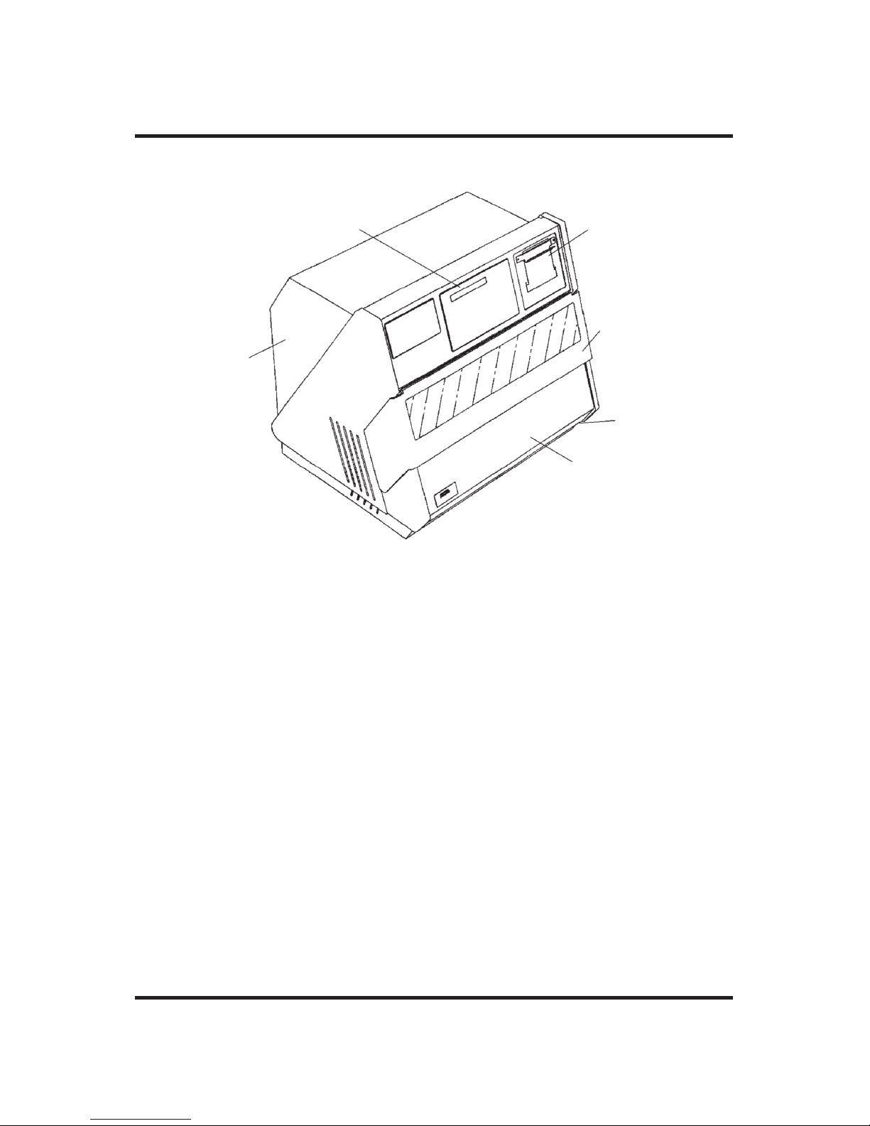
Figure 1: Model 3900 Osmometer and Accessories
Page 22
Damage,” and file your claim. Then, notify Advanced Instruments
immediately for repair or replacement.
e. Fill out the postage-paid (U.S.A. Only) warranty card enclosed. Mark
the appropriate boxes if you wish to receive additional information.
Customers outside of the United States may fax the warranty card to
781-320-8181.
Step 3 — Setup and installation
The following additional unpacking and installation procedures should
be accomplished before power is applied to the instrument:
1. Open the magnetically held, drop-down,cassette deck cover (see figure 2) by pulling its frame forward and down.
2. Remove the two screws and top half of the operating head shipping
4
The Advanced®Osmometer Model 3900 User’s Guide
Figure 2: Major Parts and Controls
Display Panel
and Keypad
Measurement &
Control Circuit
Boards (inside)
Air Filters
Thermoelectric
Refrigeration
(inside)
Printer Door
Cassette Deck
Cover
Page 23
5
Installation & Setup
fixture (see figure 3, note A); store them in case of possible future
transport of the instrument.
Figure 3: Additional Unpacking Steps
A. Operating head must always be held down by fixture during shipment. Remove two
screws and top half of fixture before powering instrument.
B. Freezing chamber must be plugged during shipment. Remove freezing chamber
plug before powering instrument.
C. A dry probe wiper must be used to protect probe during shipment. Lift operating
head and remove protective material from probe and stir/freeze wire; manually
rotate operating head forward; gently lower probe between decks before powering
instrument.
A
C
B
WARNING!
Page 24
6
The Advanced®Osmometer Model 3900 User’s Guide
3. Remove the plug and O-ring from the sample freezing chamber (see
figure 3, note B) and store them in case of possible future transport
of the instrument.
4. Lift the operating head and remove the protective material (see figure 3, note C) from the probe and stir/freeze wire and from the insert
(STAT) test well. Then manually rotate the operating head forward to
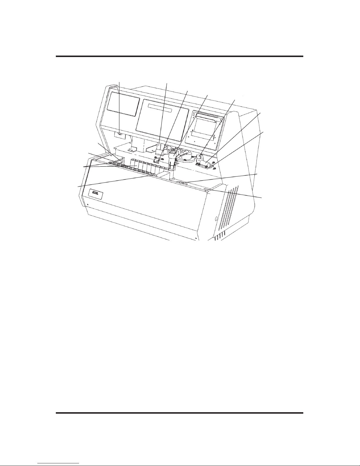
Figure 4: Cassette Deck
A
H
I
J
K
L
M
B
C
D
E
F
G
A. Heat Transfer Fluid Port
B. Numbered Cassettes (in running
position)
C. Input Deck
D. Cassette Pusher
E. Supervisor/Operator Keyswitch
F. Probe Wipers
G. Insert (STAT) Test Well
H. Operating Head
I. Head Position Adjuster
J. Drip Catcher
K. Sample Freezing Chamber
L. Cassette Index Mechanism
M. Output Deck
Page 25

the position shown in figure 4 and gently lower the probe between
decks to avoid damage.
5. Install new drip catcher sponge (see figure 4). Make sure that the
new installation is lined up so that it does not obstruct the head
motion.
6. Install two wiper sponges as probe wipers (see figure 4).
7. A small port for draining the insert test well and any liquid spills in
the deck area is located under the left center of the instrument. A
shallow sponge or tray, such as one of the 4C3035 cassette storage
trays, may be placed under the drain port to catch any vented liquid.
8. Remove the fluid ship cap (solid) from the heat transfer fluid port
(see figure 4). Install the vented fluid plug provided with the instrument.
NOTE Save and store the solid fluid ship cap. If the instrument is
returned for any reason, the vented fluid fill plug must be
removed and the solid fluid ship cap reinstalled as part of
the preparations for shipment.
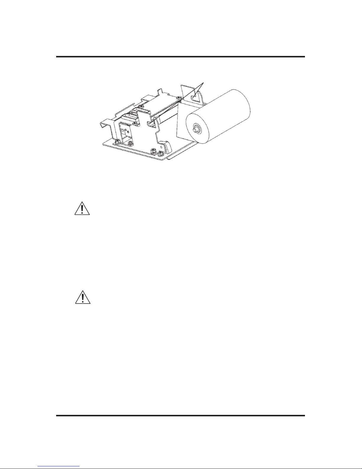
Step 4 — Load printer paper
A roll of thermal printer paper and a paper roll holder are supplied with
the instrument. These must be installed in the printer as follows:
1. Unroll 6-8” (25-30 cm) of paper from the paper roll.
2. Fold one corner of the end of the paper to form a 4-6” (15-25 cm),
blunt-tipped, tapered point. Crease the fold so that the doubled part
will not be thicker than two thicknesses of paper.
3. Open the printer door (see figure 2) by pulling the top of the door
forward and down.
4. Feed the folded tip of the paper from the top of the roll (as shown in
figure 5) into the slot at the back of the printer.
7
Installation & Setup
Page 26
CAUTION The paper should only be pushed or pulled forward
through the printer; attempting to pull the paper backward through the printer may cause printer damage.
5. Push the paper in far enough for the end to slightly protrude from the
paper output slot in the printer door.
6. Grasp the protruding tip of paper and gently pull 2-4” (8-15 cm)
straight out of the slot in the printer door while, with the other hand,
centering the paper being drawn in.
CAUTION If the paper is not carefully centered as it is being drawn
into the printer, its edges may fray or tear, causing the
paper to jam in the printer.
If the printer paper becomes jammed under the print
head, a protective circuit will shut off the printer without deactivating the display or the rest of the instrument.
To reactivate the printer, shut off the 3900, and then
clear the paper jam and turn the power back on. If the
paper jam has been successfully cleared, the instrument
will complete the power-up cycle described in step 6
and reactivate the printer.
8
The Advanced®Osmometer Model 3900 User’s Guide
Figure 5: Loading Printer Paper
Roller Slots
Page 27

7. Insert the paper-roll holder into the paper roll, center it and drop the
roller ends into the roller slots (see figure 5).
8. Pull enough paper through the printer to take up any slack between
the paper roll and the printer.
9. Close the printer door and take up any slack by pulling the end of
the paper.
Step 5 — Obtain additional items
The following items are not supplied by the manufacturer:
• Soft, no-lint, non-ionic paper tissues are needed for cleaning the
sample probe prior to testing. Please be sure that you have an adequate supply on hand before attempting to run tests on your instrument.
• Clean, dry 0.2 to 0.3mL pipet.
Step 6 — Power up your instrument
When the instrument has been unpacked and installed as recommended
in steps 1-5, it may be started as follows:
1. Make sure the power cord is connected to the 3900 and the power
outlet.
9
Installation & Setup
Reservoir
Drain Port
Reservoir Pump
Pushbutton
Figure 6: Back Panel
Serial Communications Port
Bar Code Port
Power Module
Page 28

2. Place the POWER switch on the back of the instrument (see figure 6)
in the on ( | ) position. Each time it is turned on, the 3900 prints the
instrument model, software version, copyright notice, serial number,
date and time and the probe bin numbers. Your readout should look
similar to the following.
Model 3900
Version 3.4
(C) 2000 A. I., Inc.
Serial#:123456789012
01/30/2000 11:09 am
[ON]< Batch *[OFF]
[ON]< Barcode *[OFF]
[low]* Range>[high]
[glass] * > [plastic]
“Buzz” point =3000
Amplitude = 35
Block: 5 Sample: 3
Save the printed information with the service log at the end of this
user’s guide to facilitate any necessary service.
If the instrument does not contain heat transfer fluid, “Fluid
Required” is briefly displayed, then “Fluid Level=Empty” is displayed. See step 7 for filling instructions.
Step 7 — Install heat transfer fluid
CAUTION The heat transfer liquid contains hazardous chemicals.
Consult the material safety data sheet (MSDS) and use
appropriate personal protective equipment.
1. Locate the funnel and two bottles of heat transfer fluid and the heat
transfer fluid operation plug.
2. Open the magnetically held, drop-down, cassette deck cover (see figure 2) in the front of the 3900 by pulling its frame forward and down.
3. With the cassette deck cover dropped down, open the heat transfer
10
The Advanced®Osmometer Model 3900 User’s Guide
Page 29

fluid port in the divider between the two sides of the sample tray
deck by removing the vented fluid fill plug (see figure 4).
4. Insert the funnel into the heat transfer fluid port.
5. Paying attention to the display, carefully pour heat transfer fluid into
the heat transfer fluid port. As the reservoir is filled, the display will
change from “Fluid Level=Empty” to “Fluid Level= Low”, to
“Fluid Level=Half”, and then to “Fluid Level=Full”, and then
“Press START to Continue” is continuously scrolled across the dis-
play. From “Empty” to “Full” requires about 225-mL (about 1.5
bottles).
CAUTION Pouring the heat transfer fluid too quickly without allow-
ing sufficient time for the display to update may result in
overfilling the reservoir and fluid spillage.
6. Without opening the drain port, press and hold the reservoir pump
push button for approximately 30 seconds to prime the heat transfer
fluid flow through the freezing chamber.
7. Remove the funnel and close the heat transfer fluid port by installing
the vented fluid fill plug.
8. A spare supply of heat transfer fluid should be ordered immediately.
Heat transfer fluid is gradually expended during operation because a
small amount clings to the outside of each sample tube tested; also,
some fluid gradually evaporates. When the fluid level reaches the
“Fluid Level= Empty” indicator, heat transfer fluid will again be
required.
The heat transfer fluid reservoir status may be checked before it
reaches “Empty” by means of the “Reservoir Status” SETUP menu
item (see Setup section).
NOTE It is not recommended to top off the existing bottle of heat
transfer fluid, due to moisture and growth that exist. Always
discard the old bottle and fluid and replace with a new bottle.
11
Installation & Setup
Page 30

NOTE Should it become necessary to move the instrument to another
location after the heat transfer fluid has been installed, take
appropriate precautions to prevent fluid spillage.
Step 8 — Run self-diagnostic test
During power-up, the scrolled display, “Press START to Continue”,
indicates that the instrument is required to check for proper operation by
running a test sample in a cassette. Only a single sample will be run at
this time. The instrument operator should load and start the selfdiagnostic test as follows:
1. Pipette or measure a 0.2 to 0.3-mL sample (H
2
O is OK) into a sam-
ple tube and place it in the first position in a sample tube cassette.
2. Place the cassette in the left (input) deck (see figure 4) with the cassette identification number facing you.
3. Press START.
While the self-diagnostic test is running, “Running Diagnostics” is displayed. When the 3900 has completed the self-diagnostic test,
“Osmometer Ready” is displayed and the instrument is ready for regular testing. Please turn to Chapter 2 for operating instructions.
If the probe data has been lost from memory, “Reset Probe
Configuration” will be displayed and printed, the instrument will
switch to the SETUP menu and one should contact Advanced Hot-Line
®
service before proceeding further.
Step 9 — Proceed to instrument operation
If you have followed the steps outlined in this chapter, your instrument
is ready for use. To learn how to operate your instrument, read the next
chapter, Instrument Operation. We strongly recommend that you read
the entire second chapter before attempting to operate your osmometer.
12
The Advanced®Osmometer Model 3900 User’s Guide
Page 31

2
Instrument Operation
In order to run your instrument properly, it is important that
you read and adhere to the instructions in this section. For
information on calibration, see Chapter 4 — Calibration.
Hazardous material cautions
• WARNING: Handle all biohazardous materials according to
established good laboratory practices and follow your institution’s exposure control plan. Persons handling human blood
and body fluid samples must be trained in blood-borne hazards and observe universal precautions. Universal precautions
is an approach to infection control, where all human blood and
body fluids are treated as if known to be infectious. Use personal protective equipment such as gloves, gowns, etc., to prevent exposure. Store biohazardous materials in regulated
waste containers and dispose of these materials in a safe and
acceptable manner that is in compliance with all country, state
and local requirements.
CAUTION The heat transfer fluid contains hazardous chemi-
cals. Consult the material safety data sheet (MSDS)
and use appropriate personal protective equipment.
• Heat transfer fluid can become contaminated with sample
material which may be considered a biohazard. Use appropriate cautions during removal and disposal of sample tubes
after testing to prevent heat transfer fluid remaining on the
tube exterior from contacting personnel or the instrument
surface.
13
Page 32

The Advanced®Osmometer Model 3900 User’s Guide
• If a biohazardous material is spilled on or inside the equipment,
decontaminate the equipment using a 1% bleach solution, or as outlined by those policies and procedures established within your institution.
• To avoid injury or fire hazard, do not operate this product in an explosive atmosphere.
Function of major components
Operation of the instrument will be quicker and easier if you become
familiar with the locations and functions of the components, systems and
controls described below before proceeding further.
Functionally, this microprocessor-controlled instrument consists of automatic sample holding and centering devices, a precision digital thermometer, cooling and freezing chambers, measurement and control circuitry, a keypad and a message display panel. These basic systems
include the following parts and controls:
Power Module (Figure 6)
Contains the following power components:
• Power Switch
Press ( | ) for power on, (O) for power off. The power may be left on
continuously.
• Power Cord Connector
To accommodate a power cord suitable for the power available.
• Fuse Holder
For containing fuses suitable for the power available.
Bar Code Port (Figure 6)
A D-type 15-pin bar code port in the back of the instrument is intended
for attachment of an optional bar code scanner, as described in Bar
Code Scanner section.
14
Page 33

15
Serial Communication Port (Figure 6)
The serial port can reliably communicate over shielded cable up to 10
meters in length. Data is transmitted asynchronously as 1 start bit, 8
data bits, and 1 stop bit with no parity. Hardware handshaking is supported; XON-XOFF software handshaking may be selected by means of
the SETUP menu (see Setup).
The default serial data rate is 1200 bps (bits per second), though 300
bps and 9600 bps may alternatively be selected (see Setup).
Each message transmitted from the communication port is terminated
by the sequence, Carriage Return (0D Hex), Line Feed (0A Hex), Null
(00 Hex). For display purposes, most messages consist of less than 20
characters but longer messages, which scroll across the display, are
transmitted no differently.
The 3900 transmits a significant amount of information via the communication port. Almost every item of information displayed by the instrument can be transmitted over the port, including test results, all error
messages, and most display data from the TEST menu.
The serial communication port conforms to the DTE EIA-232/V.24 (RS-
232) standard and its pin assignments are shown in table 2.
Reservoir Pump Pushbutton (Figure 6)
Used to control the heat transfer fluid pump to prime, flush and drain
the heat transfer fluid reservoir and cooling chambers.
Reservoir Drain Port (Figure 6)
Used with the quick-connect connector and short length of tubing supplied, to drain and flush the heat transfer fluid cooling chambers.
Supervisor/operator Keyswitch (Figure 2)
The operator (horizontal) position of the supervisor/operator keyswitch
provides a means of locking out the setup, test and calibration functions
of the instrument to help prevent unauthorized changes.
Instrument Operation
Page 34

The Advanced®Osmometer Model 3900 User’s Guide
The operator keyswitch position only allows access to the START sample test, INSERT (STAT) sample test, STOP, paper FEED and RECALL
functions; the Supervisor keyswitch position additionally allows access
to the SETUP, CALIB rate and TEST functions.
If the SETUP or TEST button is pressed while the supervisor/operator
keyswitch is in the operator (horizontal) position, a “Supervisor Key
Needed; Press STOP to Continue” message is continually scrolled
across the display until STOP is pressed. When STOP is pressed, the
message will change back to “Ready”, re-enabling the sample test
function.
The CALIB button has no effect until the instrument has completed the
power-up diagnostic checks. If the CALIB button is pressed after the
instrument has completed the power-up diagnostic checks and the
supervisor/operator keyswitch is in the operator position, a “Supervisor
Key Needed; Press STOP to Continue” message is continuously
scrolled across the display until STOP is pressed.
Sample Tube Cassettes (Figure 4)
Other than priority “INSERT” tests, all tests should be run on samples
in tubes loaded into the cassettes provided. The cassettes contain magnetic identification and sample location.
16
Carrier Direct 1 to 3900
Receive Data 2 to 3900
Transmit Data 3 from 3900
Data Terminal Ready 4 from 3900
Signal Ground 5 common
Data Set Ready 6 to 3900
Request to Send 7 from 3900
Clear to Send 8 to 3900
Signal Pin Direction
Table 2: Communications Port Connections
Page 35

Calibration Cassette (optional)
A specialized cassette that initiates recalibration.
Cassette Pusher (Figure 4)
Pushes each cassette in the left (input) deck into proper position for the
cassette indexing mechanism.
Cassette Index Mechanism (Figure 4)
Indexes the most rearward cassette in the left (input) deck to the right,
one position at a time, to sequentially present each sample tube to the
operating head for testing.
Insert Test Well (Figure 4)
For single, priority tests.
Sample Freezing Chamber (Figure 4)
Thermoelectric for reliability and precise control. Contains a small
amount of heat transfer fluid for optimum cooling capacity.
Heat Transfer Fluid Pre-cooling Chamber (inside)
Thermoelectrically pre-cools heat transfer fluid for faster operation.
Operating Head (Figure 4)
Contains an electrically vibrated stir/freeze wire; an ultra-stable, ultraprecise thermistor sample probe and devices to automatically center the
thermistor in the sample. Picks up the positioned sample tube and places
it in the sample freezing chamber for testing. After the freezing point
test, the operating head returns each sample tube to its proper position
in the cassette.
Measurement and Control Circuit Boards
Provide operating mode and calibration selections on the display during
setup.
17
Instrument Operation
Page 36

The Advanced®Osmometer Model 3900 User’s Guide
Automatically measure and control the dynamic temperature of the sample freezing chamber. Process calibration data and sample temperature
information. Transmit calibrated test results to the display and printer.
Printer
The printer is mounted on an easy-access swing-down door. If no printer paper is protruding or if the printer stops printing the information displayed on the display panel, please refer to Step 4 - Load Printer Paper
.
Display Panel and Keypad (Figure 2)
The microprocessor communicates with the instrument operator by
means of alphanumeric messages on the illuminated display panel located at the top of the keypad and printed on paper tape. These messages
report the instrument function currently being performed, the next operator function required and the results of tests. The messages are displayed either in English, French, German or Spanish, as selected via the
SETUP menu; the default language is English.
The keypad contains spill-proof delineated pressure buttons for operator
input to the microprocessor. Switch activation requires firm finger pressure to the center of the pad. When pressed properly, the START, STOP,
INSERT, RECALL, SETUP, TEST, and CALIB buttons illuminate to
indicate activation.
For a complete listing of buttons and their functions, see Table 3, “The
Function of Keypad Switches”.
Bar code scanner (optional)
In conjunction with a commercially-available bar code scanner, the
Model 3900 can provide automatic identification of each sample on the
printed results. A D-Type, 15-pin bar code port is provided in the back
of the 3900 for connecting and providing power to such a device. For
proper operation, the bar code port requires a 1200 bps, TTL-level signal providing asynchronous serial data containing 1 start bit, 8 data bits,
18
Page 37

19
Instrument Operation
START Starts CALIB, TEST and SETUP procedures, as well as freezing point tests.
Cancels the procedure in process.
STOP During certain multiple-step procedures, pressing STOP once stops the current
action; pressing STOP a second time cancels the procedure.
INSERT Interrupts the test sequence in progress (after the current test), to allow testing
a priority sample, after which the original test sequence is resumed (see Stat
Tests).
FEED Advances the printer paper for paper loading, or for advancing data beyond the
tear line.
RECALL Recalls and prints the most recent test results and messages (see Recall).
SETUP Activates the SETUP menu which may be used to set the current date and time,
activate the keypad "beeper", select the communication parameters, etc. (see
Setup).
TEST Activates a "test" menu for checking selected components and subsystems (see
Test).
CALIB Activates calibration prompts for calibration of the instrument. Pressing STOP
during a calibration test will cancel recalibration and retain the previous calibration (see Calibration).
Numbers 1 Allow prompted numeric operator input, as required, during SETUP, CALIB
through 0 and TEST procedures.
< and > Allow stepping forward and backward through displayed menu items as an
alternative to selection via the numeric pads and allow making alternative twoitem menu choices.
CLEAR Can be used to empty the date and time and/or % DFB "Base Value" memory
fields during SETUP. If batch numbering has been enabled, CLEAR can also
be used to empty the sample identification number and "# of Samples" memory
fields.
ENTER Confirms the selected SETUP menu item. If sample identification has been
enabled, ENTER is used to confirm the sample identification.
The Function of Keypad Switches
Table 3: The Function of Keypad Switches
Page 38

+5V DC 1 to reader
receive data 10 from reader
gnd/earth 9 common
Signal Pin Direction
Table 4: Bar Code Port Connections
1 stop bit and no parity. The bar code port pin assignments are shown
in Table 4.
A suitable bar code scanner is available from Advanced Instruments,
Inc. or an authorized dealer. To interface with the Model 3900, the bar
code scanner must be programmed as follows, referring to the scanner
users guide:
1200 bps
CR suffix
disable beep after good decode
triggerless trigger mode (optional)
Setup
Your 3900 has been set up at the factory for normal operation, but the
SETUP menu may be required for changing the date and time or customizing the setup parameters for your own individual needs.
NOTES
a. The supervisor/operator keyswitch must be in the supervisor
(vertical) position to enable the use of the SETUP menu. If the
SETUP button is pressed while the supervisor/operator keyswitch
is in the operator position, a “Supervisor Key Needed; Press
Stop to Continue” message will be displayed.
b. The instrument setup is stored in firmware which can easily be
updated at the factory to incorporate possible additional setup
items or refinements. The following list includes all currently
20
The Advanced®Osmometer Model 3900 User’s Guide
Page 39

implemented setup functions in the order in which they appear in
the SETUP menu; however, the order in which they appear may
change slightly if the firmware is later updated to include additional SETUP items.
The operating parameters that may be checked and set via SETUP are
shown in Table 5.
Enter SETUP, if required, by pressing the SETUP button. When SETUP
is pressed, the display will change to “Select Setup Item”.
There are two ways to select a SETUP menu item, direct selection and
sequential selection, described as follows:
0. Select Setup Item
This menu item is displayed first when SETUP is pressed and allows
either direct selection or sequential selection of a menu item.
21
Instrument Operation
0. Select Setup Item
1. Set Block Bin #
2. Set Sample Bin #
3. Select Batch
4. Select Barcode
5. Set Stir Amplitude
6. Set Date/Time
7. Select Beeper
8. Set Serial Rate
9. Select Data Capture
10. Select Xon/Xoff
11. Serial Number
12. Select Range
13. Set "Buzz" Point
14. Select Language
15. Product/Test
16. Reservoir Status
Setup Mode Options
Table 5: Setup Menu Options
Page 40

The Advanced®Osmometer Model 3900 User’s Guide
Direct Selection: for direct selection, press START at “Select Setup
Item”. The display will change to “Setup Menu #: 0”. At “Setup
Menu #: 0”, enter the number of the desired setup item (from the list
above) on the keypad and press ENTER. The display will change to
the selected menu item.
Sequential Selection: for sequential selection, repeatedly press the >
button to step the display forward or < to step the display backward
through the setup menu list. The displayed parameter list is cyclic;
pressing > at the last item cycles the display to item 0. Continue
pressing > or < until the desired menu item is displayed.
Note that while direct, numerical selection is only available at
“Select Setup Item”, > or < stepping is available from any menu
position.
When the desired menu item is displayed, press the START button to
select the item, display the current setting, and enable changing the
setting.
The current setting is indicated either by the symbol “*” or a numeric value and may be changed by pressing > or < (or using the itemspecific instructions below).
Press ENTER to store a new setting (or STOP to restore the original
setting). The display will revert to the title of the parameter selected.
Then one may press: START to display the new setting, > or < to
step to the next SETUP item, STOP to exit the SETUP menu, or
TEST to change to the TEST menu.
Recommended procedures for each of the other SETUP menu items
are as follows:
1. Set Block Bin #
This menu item displays the current block probe bin setting and
allows the setting to be changed. However, the block probe bin setting should only need to be changed when a new block probe of a
22
Page 41

different bin number is installed. In that case, make sure the new
block probe bin number is recorded in the Service Log at the back of
this user’s guide and proceed as follows.
NOTE Changing the bin setting requires recalibration of the instru-
ment.
At “Set Block Bin #”, press the START button. The display will
report the current block bin setting. Compare the current block bin
setting with the new block bin number recorded in the service log.
If the current block bin setting is the same as that recorded in the
service log, simply press the STOP button to return to “Set Block
Bin #”. If the current bin number is not the same as the new bin
number, enter the required bin number by means of the numeric keypad.
Press ENTER to store the new setting (or STOP to restore the original setting).
Recalibrate the instrument as instructed in Calibration.
2. Set Sample Bin #
This menu item displays the current sample probe bin setting and
allows the setting to be changed.
CAUTION Before changing the probe bin setting, the required set-
ting should be determined by means of the procedure
described in Troubleshooting & Service. Changing the
bin setting requires recalibration of the instrument.
At “Set Sample Bin #”, press the START button. The display will
report the current sample bin setting. Compare the sample bin setting
with the sample bin number determined by means of the procedure
described in Troubleshooting & Service.
If the current sample bin setting is the same as that determined in
Troubleshooting & Service, simply press the STOP button to return
23
Instrument Operation
Page 42

The Advanced®Osmometer Model 3900 User’s Guide
to “Set Sample Bin #”. If the bin number is not the same, enter the
required bin number by means of the numeric keypad.
Press ENTER to store the new setting (or STOP to restore the original setting).
Recalibrate the instrument as instructed in Calibration.
Be sure to record the new sample bin setting in the Service Log at
the back of this user’s guide.
3. Select Batch
This menu item enables a means of entering a batch identification
number of up to 4 digits for each batch of tests and the number of
samples in the batch.
When enabled, the 3900 prompts for the batch identification number
to be entered via the numeric keypad each time a batch of tests is
started by pressing the START button. Identification numbers are
then sent to the printer and the communication port along with the
test results.
At “Select Batch”, press START to display “[ON]< Batch *
[OFF]”. The current setting is indicated by the symbol, “*”.
At “[ON]< Batch * [OFF]”, press < or > to toggle the batch identification option on or off.
Press ENTER to store the new setting (or STOP to restore the original setting).
4. Select Bar code
This menu item enables a means of entering an identification number
of up to 16 characters for each test by means of an optional reading
device connected to the bar code port in the back of the instrument
(see figure 6 and Bar code Scanner section).
24
Page 43

At “Select Barcode”, press START to display “[ON]< Barcode *
[OFF]”. The current setting is indicated by the symbol, “*”.
At “ [ON]< Barcode * [OFF]”, press < or > to toggle the Bar code
option on or off.
Press ENTER to store the new setting (or STOP to restore the original setting).
NOTE Bar code selection automatically includes batch numbering.
5. Set Stir Amplitude
This menu item displays the current sample stir amplitude setting
and allows the setting to be changed.
At “Set Stir Amplitude”, press START to display “Amplitude =
xx”.
At “Amplitude = xx”, look across the tip of the stir/freeze wire from
the side to view and estimate the sample stir vibration amplitude. If
properly adjusted, the stir/freeze wire should vibrate principally fore
and aft and should never strike the probe. The recommended stir
amplitude adjustment procedure may be found in Troubleshooting &
Service. Pressing > increases the stir amplitude; pressing < decreases
the stir amplitude.
Press ENTER to store the new setting (or STOP to restore the original setting).
6. Set Date/Time
This menu item enables changing the date/time format and resetting
the date and time.
At “Set Date/Time”, press START to display the current date and
time. Any change must be made in this order:
a. Press CLEAR to clear the entire setting and display the present
format.
25
Instrument Operation
Page 44

The Advanced®Osmometer Model 3900 User’s Guide
b. Use < to toggle to the date format you require (“mm/dd/yy” or
“dd/mm/yy”).
c. Use > to toggle to “24hr” format, “am”, or “pm”, as required.
d. Enter the current date and time (including zeros), via the numeric
keypad, one digit at a time from left to right.
e. Press ENTER to store the new setting (or STOP to restore the
original setting). If an invalid setting is attempted, the instrument
will reject the setting and beep when ENTER is pressed.
7. Select Beeper
The 3900 keypad in itself has no audible indication that a button has
been adequately pressed. The Select Beeper menu item enables an
audible indication.
At “Select Beeper”, press START to display “[ON]< Beeper *
[OFF]”. The current setting is indicated by the symbol, “*”.
At “[ON]< Beeper * [OFF]”, press < or > to toggle the keypad
beeper on or off. Neither selection will affect the invalid-selection
beeper except that, when the keypad beeper is on, an invalid selection will invoke two beeps, when off, only one.
Press ENTER to store the new setting (or STOP to restore the original setting).
8. Set Serial Rate
This menu item enables changing the serial rate of the data sent to
the communication port.
At “Set Serial Rate”, press START to display “Serial Rate = xxxx”.
At “Serial Rate = xxxx”, the serial-port baud rate may be reset by
means of the < or > button to either 300, 1200 or 9600 bps.
Press ENTER to store the new setting (or STOP to restore the original setting).
26
Page 45

9. Select Data Capture
The EIA-232/V.24 communication port normally communicates only
the final result of each test. When implemented, this menu item
enables or disables communication of data taken throughout each
freezing point curve to a PC with data capture software for troubleshooting or research purposes. Data Capture transmits data at 9600
bps and sets the communication port serial rate accordingly. Do not
select any other serial rate while Data Capture is enabled.
At “Select Data Capture”, press START to display “[ON]< Capture
*[OFF]”. The current setting is indicated by the symbol, “*”.
At “[ON]< Capture *[OFF]”, press > or < to enable or disable communication-port data capture.
Press ENTER to store the new setting (or STOP to restore the original setting).
10. Select Xon/Xoff
This menu item enables or disables the Xon/Xoff handshaking protocol for EIA-232/V.24 communication.
At “Select Xon/Xoff”, press START to display “[ON]< Xon/Xoff
*[OFF]”. The current setting is indicated by the symbol, “*”.
At “[ON]< Xon/Xoff *[OFF]”, press > or < to enable or disable serial port Xon/Xoff handshaking.
Press ENTER to store the new setting (or STOP to restore the original setting).
11. Serial Number
At “Serial Number”, press START to display the in stru ment serial
number (e.g., “Serial#: 123”).
Press ENTER to return to the setup menu.
27
Instrument Operation
Page 46

The Advanced®Osmometer Model 3900 User’s Guide
12. Select Range
The Model 3900 can operate in “Low” or “High” range depending
upon the expected sample result range. “Low Range” optimizes
operation for results between 0 and 1550 mOsm - “High Range”
between 1450 and 4000 mOsm. Because most applications do not
require High Range operation, all Model 3900 osmometers default
to Low Range. High Range operation may be selected by the following procedure:
At “Select Range”, press START. “[low]* range >[high]” will be
displayed and the high range may be selected. The current setting is
indicated by the symbol “*”. Press < or > to toggle between the low
and high ranges.
If the low range is selected, you will be prompted to select glass or
plastic sample tubes. It is important that you make this selection as
internal operating parameters will be revised to optimize the instrument’s performance based upon type of sample tube.
Press ENTER to store to store the new setting (or STOP to restore
the previous setting).
Check the calibration; recalibrate as necessary. Both ranges were
calibrated at the factory.
If switching from low to high range, the Model 3900 may need time
to adjust the cooling system for optimal operation. This procedure
may take 2-3 minutes. To avoid delays in operation, the operator
may wish to observe the equilibrium period and make sure calibration is successfully started before leaving the Model 3900 to run
automatic calibration.
13. Set “Buzz” Point
This menu item enables setting the temperature at which crystallization is induced by the freeze pulse (buzz) in each range.
Most freezing point osmometers supercool all samples in the 01550 mOsm range to approxi mately 3000 on the mOsm scale; the
28
Page 47

Model 3900 buzz point defaults to 3000 for the lower range and
4800 for the upper range. Because the test results may be affected
somewhat by the amount of super cooling, these default buzz points
are recom mended for general use and for the most reliable comparison of data.
Certain fluids may not freeze reliably at the default buzz point, however, or may give more repeatable results with either more or less
supercooling than the default buzz point provides. The Model 3900
is designed to accommodate these, as well as the more ordinary
types of samples.
At “Select “Buzz” Point”, press START to dis play the current crystallization setting, displayed as “Buzz” Point = xxxx”. To change
the crystal lization point:
a. At “Buzz” Point = xxxx”, the present setting must be cleared
before the buzz point can be changed. Press CLEAR to clear the
setting.
b. Enter the desired buzz point (including zeros), via the numeric
keypad, one digit at a time from left to right. Entries can be
erased one digit at a time from the rightmost using the < button.
The Model 3900 buzz points can be set between 2000 and 5400
on the mOsm scale.
Press ENTER to store the new setting (or STOP to restore the original setting).
Note Each time the buzz point is changed, the instrument displays
the message “Check Calibration”, a reminder that the
instru ment calibration is affected by the amount of supercooling.
14. Select Language
Due to memory limitations, only one language may be installed.
Contact your dealer or Advanced Instruments for availability of
additional languages.
29
Instrument Operation
Page 48

The Advanced®Osmometer Model 3900 User’s Guide
15. Product/Test
Product/Test is for factory use only and has no field function.
16. Reservoir Status
This menu item provides information when filling the heat transfer
fluid reservoir.
At “Reservoir Status”, press the START button. The display will
report the present state of the reservoir.
If the reservoir is empty, the display will be “Fluid Level =
EMPTY”. As the reservoir is filled, the display will change sequentially to “Fluid Level = LOW”, “HALF” and “FULL”.
Press STOP to return to the setup menu.
Operating instructions
Each time the Model 3900 is turned on, it displays and prints the information described in Installation & Setup, checks its heat transfer fluid
level, then runs a self-diagnostic test which requires running a single
sample as de scribed in Installation & Setup. As soon as the self-diagnostic test is completed, “Osmometer Ready” is displayed.
The Model 3900 requires no refrigeration cool-down time; samples may
be loaded and tested as soon as “Osmometer Ready” is displayed (the
first few sam ples will exhibit a slightly-longer test time until the reserve
heat transfer fluid cooler reaches its operating temperature). For maximum throughput speed, the Model 3900 may be left on continuously.
Your Model 3900 was calibrated at the factory. The probe and calibration parameters are stored in RAM which is powered by an internal battery when the instrument power is off or disconnected. Thus, when
“Osmometer Ready” is displayed, your osmometer is calibrated and
ready to run.
When the Model 3900 does not have enough heat transfer fluid at
power-up or after “Osmometer Ready” has been displayed for five
30
Page 49

minutes, “Fluid Required” is briefly displayed and the heat transfer
reservoir should be filled as described in Installation & Setup.
Sample Tubes and Sample Sizes
Different sample tube styles and sample sizes should not be used
together because each may require a different instrument adjustment
and/or calibration. Sample tubes should be as uniform as possible in
composition, shape and size.
Glass tubes generally are not as uniform in shape and size as plastic
tubes, nor do they thermally isolate test samples as well. The Model
3900 operating parame ters are optimized for Advanced Instruments
plastic sample tubes—do not expect the same repeatability using glass
tubes. If you need further information con cerning sample tube requirements, please contact Ad vanced Instruments.
Samples should always be pipetted or measured; 0.2 to 0.3-mL samples
may be used. To achieve the performance specified, we recommend
that you use 0.25-mL sam ples. For pediatric use, 0.2-mL samples may
be more desirable but will require somewhat more critical probe and
stir/freeze wire adjustment for similar precision in results. Where high
sample evaporation is a factor, 0.3-mL samples can help maximize
repeatability. Os mo meters should always be calibrated with the same
sample size used for testing.
Storage and Handling of Supplies and Accessories
• Calibration Standards—Unopened calibration standards and reference solutions should be stored at 39°F to 86°F (4°C to 30°C).
Protein controls should be stored at 36°F to 43°F (2°C to 6°C).
Expiration dates are printed on the package labels. After opening,
avoid contamination and evaporation.
• Heat Transfer Fluid—The heat transfer fluid supplied should be
installed as described in Chapter 1. Spare heat transfer fluid may
be stored at room temperature.
• Sample Tube Cassettes—Do not expose the sample cassettes to
temperatures above 180°F (82°C).
31
Instrument Operation
Page 50

Sample Preparation
No further sample preparation is required. Body fluids such as serum
or plasma may be used directly.
NOTE Additives such as anticoagulants from collection tubes may
contribute signifi cantly to the measured osmolality.
Particulate matter can cause premature crystallization; in blood it is normally eliminated by centrifugation. Particulate matter in urine may be
removed by centrifu gation or filtration through an inert filter.
Sample test procedure
If the Model 3900 has been turned off, it should be started as indicated
in Installation & Setup.
The default range is 0-1550 mOsm and the default “buzz” point is
3000 mOsm. If the expected freezing points are in the 1450-4000
mOsm range and the op tional high range has been implemented, the
high range should be selected before beginning a set of tests. If the
freezing point of a sample is not within the range selected, a message
will be dis played, requesting the range be changed.
Like most measuring instruments, osmometers need calibration against
standards. Your Model 3900 was calibrated at the factory using the procedures described in Calibration. The probe and calibration parameters
are stored in parameter RAM which is powered by an internal bat tery
when the instrument power is off or disconnected. Thus, when
“Osmometer Ready” is displayed, your Model 3900 is calibrated and
ready to run. However, the calibration should always be verified during
opera tion to be sure that none of the parameters affecting calibration
have changed. In the recommended proce dure which follows, calibration verification is accom plished by starting with the Clinitrol™ reference solu tion. Then, if recalibration is required, see Calibration.
It is important that if you are running in low range you select the correct sample tube type you are using, (glass/plastic). Use the range
32
The Advanced®Osmometer Model 3900 User’s Guide
Page 51

selection feature in Installation & Setup to make this selection. Failure
to select the right material may affect instrument performance.
If either batch numbering or bar code scanning has been enabled, follow
the procedure in Installation & Setup before re turning to the following
steps. If neither batch num bering nor bar code scanning has been
enabled via the setup menu, instrument operation in the following manner is recommended:
1. Check the probe wipers (see figure 4). Replace the wiper sponges
when they begin to appear dirty or about every 50 tests.
Check the drip catcher (see figure 4). Replace the drip catcher
sponge when it appears dirty, ineffec tive or shows excessive wear.
2. Gently wipe the mandrel, probe and stir/freeze wire (see figure 7)
with a pure water dampened tis sue to remove any contaminant from
prior tests; re-wipe after about every 50 tests. Be careful not to bend
the probe or stir/freeze wire.
3. Select a reference solution or NaCl standard with a freezing point
close to that expected for your unknown (Advanced Clinitrol™ 290
is recom mend ed for serum). Swirl and carefully open an ampule of
the reference solution (or NaCl standard) selected.
4. Select two clean sample tubes. Pipet or measure identical samples of
the selected reference solution or NaCl standard into the clean sample tubes and place the tubes in the first two positions of the first
cassette.
5. Depending upon your required protocol, pipet or measure additional
samples of reference so lution or NaCl standards into identical sample tubes and load them into the next positions in the cassette to
check repeatability and accuracy before running tests on unknown
samples. Follow the techniques recommended in step 6. When
checking cal ibration and repeatability with standards or refer ence
solutions, it is usually best to average the readings from three to five
aliquots of each sample to avoid error.
33
Instrument Operation
Page 52

If you are running the instrument for the first time, it is recommended that you follow the Clinitrol™ reference solution samples with
bracketing calibra tion standards to check the instrument accuracy
and linearity over the range of interest.
Routinely including Advanced Protinol® protein-based controls can
provide addi tional quality assurance.
6. Using the same techniques, unknown samples may be loaded into
any remaining cassette positions if desired.
7. Place the first cassette in the left (input) deck with the labels facing
you.
34
The Advanced®Osmometer Model 3900 User’s Guide
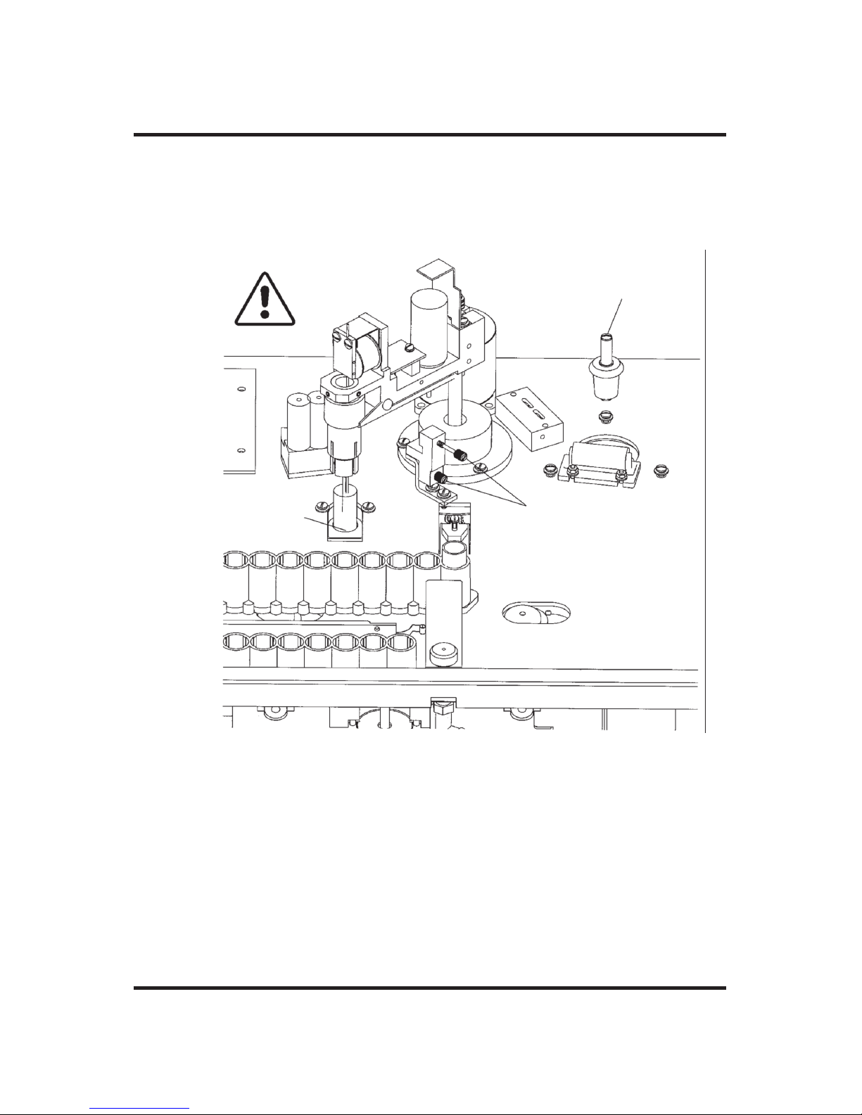
Figure 7: Operating Head
Stir/Freeze Wire
Probe
Leads
Clapper
Stir/Freeze
Wire
Setscrews
Tube
Gripper
Probe
Setscrew
Mandrel
Probe &
Stir/Freeze
Wire
Coil
Yoke
Pivot
Plate
Pin
Sample Probe
Connector
Gripper
Solenoid
Page 53

8. Press START. The Model 3900 will position the cassette, wipe the
probe and stir wire between the probe wipers, pick up the first sample tube, place it in the sample freezing chamber and perform the
freezing point test.
The sample temperature will be displayed as soon as it falls below
0°C. The Model 3900 will freeze the sample at the crystallization
point speci fied by the range and “buzz” point selection, follow the
plateau development, determine the osmolality and display and
record the results. After completing the test, the Model 3900 will
return the first sample tube to the cassette, wipe the probe and return
to the cassette for the second tube. Figure 8 shows the operating
head either loading or unloading the second sample tube from a cassette.
35
Figure 8: Operating Head Loading
or Unloading a Sample Tube
Instrument Operation
Page 54

The Model 3900 will automatically index and test each of the
remaining samples in the cassette in turn, then it will position and
test any other cas settes in the batch that are placed in the input deck.
NOTE If the STOP button is pressed while testing is in progress,
the current test will be discontinued and the Model 3900
will display “Press Start to Continue, Stop to Quit”. If
STOP is pressed the second time, testing will be terminated
and “Osmometer Ready” will be displayed.
If testing is stopped during a bar coded test batch, either
intentionally or through some mechanical fault, any untested
sam ples must be rescanned.
9. While the samples in the first cassette are being tested, additional
samples in the batch to be tested may be loaded into the next 1 or 2
cassettes. (Pre-loading more than one or two cassettes will risk
evaporation and/or contamination of the samples.)
CAUTIONS
a. The operating head constitutes a mov ing part while the
instrument is in oper ation; use care to avoid injury to
your self and damage to the instrument when ever introducing any part of the body inside the cover during operation.
b. Be careful not to place a cassette behind the cassette
pusher when it is in operation.
c. When running multiple cassettes operating in high range,
or the instrument is operated in a low humidity environment, use the evaporation cover to minimize readout drift
due to evaporation.
d. If a power interruption occurs during opera tion, turn the
instrument off at once and remove any sample tube that
may be on the operating head. Leave the instrument
turned off for at least 5 seconds after power has been
36
The Advanced®Osmometer Model 3900 User’s Guide
Page 55

restored (to ensure internal circuitry is re started properly), even if power restoration is immediate.
After loading samples into each cassette, the cassette may be placed
in the input deck at any time the cassette pusher is not moving.
If the accuracy and repeatability on the reference solution is satis factory, allow the instru ment to test the remaining samples. If the
accuracy or repeatability is not satisfactory, testing should be
stopped using the STOP button, and step 6 should be reviewed.
10.As the Model 3900 tests the samples in each cas sette, the cassette is
pushed into the right deck where as many as six cassettes can
accumu late. As the cassettes accumulate in the output deck, they
may be refilled with new samples and reinstalled in the deck.
NOTE
a. Cassettes cannot be reused in a bar coded test batch.
b. If either batch numbering or bar code reading has been
selected and, for any reason, the number of samples actually tested does not agree with the number of samples entered
at the prompt “# of Samples: ”, “WARNING -
Check Samples” will be displayed.
c. Cassettes should be cleaned periodically to remove the
accumulation of residual heat transfer fluid from tested
samples. This will prevent fluid from dripping on the
instrument surface as new samples are removed from the
cassettes for testing.
When all the samples in the last cassette have been tested, the
instrument will enter the standby mode and display “Osmometer
Ready”. Gently wipe the probe and stir/freeze wire with a pure
water dampened tissue to prevent contami nating subsequent tests.
Be careful not to bend the probe or stir/freeze wire.
During standby, the Model 3900 periodically checks the heat transfer
fluid level. When the Model 3900 does not have enough heat transfer
37
Instrument Operation
Page 56

fluid, “Fluid Re quired” is briefly displayed and heat transfer fluid must
be added as described in Installation & Setup.
When not in use, the Model 3900 may either be left on continuously for
maximum starting throughput speed, or it may be shut off. No refrigeration cool-down time is required. When turned on, samples may be
loaded and tested as soon as “Osmometer Ready” is dis played (the
first few samples will exhibit a slightly-longer test time until the reserve
heat transfer fluid cooler reaches its operating temperature).
If high range has been selected, the operator may be presented with a
message “Stand By for High Range Pre-Cool” and prevented from
performing any tests until the reserve heat transfer fluid reaches a set
operating temperature.
Also, if high range is selected, the operator may be presented with the
displayed message “Stand By, Pre-Cool” after pressing Start. The first
test will be delayed until the sample chamber has reached a preset temperature. This will only occur for the first test sample.
Testing batch-numbered or bar code-scanned
samples
If either batch numbering or bar code scanning has been enabled via the
setup menu, it is highly recommended that you minimize sample exposure by pressing START before loading samples.
If either batch numbering or bar code scanning has been enabled, when
the START button is pressed the instrument operator will be prompted
for a batch identification number of up to 4 digits for the batch.
At the “Batch Number: ” prompt, enter the batch identification
number one digit at a time from the left via the numeric keypad, and
press ENTER to store the setting. “# of Samples: ” will be displayed.
At the “# of Samples: ” prompt, enter the actual number of samples
in the batch (up to 60 if bar code reading is activated, up to 99 other-
38
The Advanced®Osmometer Model 3900 User’s Guide
Page 57

39
wise) one digit at a time from the left via the numeric keypad, and press
ENTER to store the setting. Do not forget to include controls and standards in the count, unless bar code scanning has been selected via the
setup menu, “Press START to Continue” will begin to scroll across
the display. At “Press START to Continue”, proceed as instructed in
Sample Test Procedure.
If the bar code option has been enabled via the setup menu, the instrument operator will first be prompted to enter the batch identification
number for the batch and the number of samples in the batch, just as
above. Then, the operator will be prompted to enter the 1- or 2-digit
cassette number.
When the cassette number has been entered, the oper ator will be
prompted to activate the bar code reading device and scan the bar
codes. Note that standards and controls must also be provided with bar
codes and scanned in the order in which they will be placed in the cassette. After each group of 10 bar codes scanned, the operator will be
prompted to enter the next cassette number. When finished scanning
the bar codes of the specified number of samples, “Scanning
Complete” will be displayed briefly, followed by “Press Start to Con tinue”.
At “Press START to Continue”, proceed as instructed in Sample Test
Procedure.
CAUTION
In order to avoid incorrect reporting of results, it is extremely
important to identify the sam ple in each cassette position and,
when bar coding has been enabled, to load the samples into each
cassette in exactly the same sequence in which they were
scanned, leaving no empty sample positions.
NOTES
a. As indicated in Sample Test Procedure, cassettes cannot be
reused during a bar coded test batch.
Instrument Operation
Page 58

40
The Advanced®Osmometer Model 3900 User’s Guide
Repeatability Tips
• Gently wipe the mandrel, probe and stir/freeze wire with a pure water
dampened tis sue to remove any contaminant’s before each set of tests,
after about every 50 tests, and after each set of tests. Be careful not
to bend the probe or stir/freeze wire.
• Sample tube cleanliness is extremely important for repeatability. New
Advanced plastic sample tubes may be expected to be clean. If glass
tubes are required, they should be washed in hot water con taining a
non-ionic detergent, rinsed in distilled water, and thoroughly dried
before each use.
• Always treat all samples uniformly before the test. Treat standards
and reference solutions the same as the unknowns. Do not intermix
different tube styles.
• To avoid contamination and evaporation, cover all samples not imme-
diately being tested.
• Dirty wipers can affect the results. Replace the probe wipers when
they begin to appear dirty (about every 50 tests).
• Use the same sample size consistently during calibration and testing.
• Samples should not be rerun; use duplicate samples for repeats.
• The first reading in any given period of operation may be slightly off
because of temperature con ditioning or residual contamination of the
probe. Subsequent readings on aliquots of the same sam ple should
group within the specifications listed in Appendix B.
• If an occasional sample produces irregular results, discard obviously
discrepant readings as long as the instrument has been producing
accurate read ings repeatedly. Repeat the reading in question on
another aliquot.
• To reduce the effects of evaporation, use the evaporation kit provided
in the accessory kit. Refer to the instructions on the cover for installation.
Page 59

b. If either batch numbering or bar code reading has been select-
ed and, for any reason, the number of samples actually tested
does not agree with the number of samples entered at the
prompt “# of Samples: ”, the message “WARNING -
Check Samples” will be displayed.
Repeatability tips
If all instructions are followed carefully and the in strument still will not
repeat, it is possible that the probe has been damaged. The probe may
be checked as recommended in Troubleshooting & Service. If a new
probe is installed, the sample probe bin number must be reset as
instructed in Installation & Setup, and the instrument must be recalibrated as instructed in Calibration. If the instru ment is still not repeating, please call or write your dealer or Advanced Instruments immediately for Hot-Line® ser vice as instructed in Troubleshooting & Service.
STAT tests
A feature of the Model 3900 is the capability to delib erately interrupt a
set of tests, insert a single STAT test, then automatically finish the original test sequence.
To interrupt a test set for a single priority STAT test, press INSERT.
The INSERT button will illumi nate. As soon as the current test is finished, “Insert Sample, Press START to Continue” will be dis played.
Pipet or measure the sample into a clean, dry sample tube as recommended in Installation & Setup, place it in the STAT test well (see figure 4), and press START. The inserted sample will be tested, recorded
as “STAT x” and replaced in the insert (STAT) test well; then routine
testing will be resumed. Additional STAT tests may be inserted the
same way, as necessary.
41
Instrument Operation
Page 60

Recall
At “Osmo meter Ready”, the RECALL button provides access (via the
printer and/or serial port, not the display) to the test results and messages stored in the instrument memory. This feature is particularly useful when the printer tape of the required informa tion is not available for
any reason.
The information is stored in serial groups called runs, a “run” being all
of the results and messages stored from the point when a cassette is
inserted and the START button is pressed, to the point when no more
cas settes or STAT samples are inserted and the instrument reverts to the
standby mode and displays “Osmometer Ready”.
When the recall button is pressed at “Osmometer Ready”,
“Recall 1 Run” is displayed. Only the results from the last run are
available if barcoding has been selected, but if barcoding was not
selected, the operator may either recall the last run accomplished or
may select up to 9 runs by means of the numeric keypad or the < or
> button. When more than one run is selected, the output runs will be
sequential, ending with the last run accomplished.
NOTE If the tests to be recalled were run with either batch number-
ing or bar code scan ning enabled, the same mode must be
enabled during RECALL for the recalled results to be valid.
42
The Advanced®Osmometer Model 3900 User’s Guide
Page 61

3
Standards & Quality
Control
Repeatability and accuracy
Two important measures of quality control are repeatability and
accuracy. Repeatability is sometimes called reproducibility or
precision. Repeatability is a measure of the ability of a method
to obtain the same result time after time on the same sample.
Repeatability is usually quantified as the standard deviation
(S.D.) of a set of mea surements normally distributed about a
mean: ±1 S.D. about the mean denotes the range of values
within which 68% of the measurements will fall; ±2 S.D., 95%.
By contrast, accuracy is a measure of how close to the “true”
value a method or measuring device has come. One can repeat
without being accu rate, but one cannot be accurate without
repeat ing well.
Standards and controls
To be accurate, all measurements ultimately must be referred to
highly reliable independent standards. Ad vanced
®
osmometers
are calibrated with standards con sisting of stable sodium chloride solutions of known freezing points which bracket those of
43
Page 62

the expected unknowns. These standards are related to the most fundamental work published on freezing points of dilute solutions, and are
traceable to the National Insti tute of Standards and Technology (formerly the National Bureau of Standards).
However, the most important osmometer determinations are made not
on sodium chloride, but on biological solutions. How accurately
osmometers determine the freezing points of precisely-known concentration of sodium chloride solutions, therefore, is only one measure of
osmometer accuracy. Another measure should involve determinations
on solutions or controls formulated to synthesize biological solutions.
Advanced Protinol
®
protein-based controls (at 240, 280, and 320 ±7
mOsm) provide control values which closely bracket those of most
serum samples. Other commercially available biological controls may
be recommended or specified in your area but are not quality controlled
by Advanced Instruments.
The Advanced 3LA028 Osmolality Linearity Set provides two 5-mL
ampules each of 100, 500, 900, 1500, and 2000 mOsm NaCl standards
for verifying osmometer linearity in accordance with CLIA guidelines.
Please check with your associations and regulatory bodies for their
guidelines and/or requirements.
Maintenance of standards
Doubts about the accuracy of standards destroy confi dence in the accuracy of the test. Repeatability is possible without accuracy in a data set.
Accuracy is possible without repeatability in a data set. The Advanced
osmometer standards are specified to be within very close tolerances.
The sodium chloride based reference and calibration solutions designed
for Advanced osmometers are sealed in glass ampules to prevent any
possibility of alteration during transit or storage. However, we recommend that you test samples from each newly-received lot and maintain
records of your test results on these standards for reference.
44
The Advanced®Osmometer Model 3900 User’s Guide
Page 63

Quality control implementation
The following recommendations outline the minimum requirements for
quality control:
1. Read, understand and follow the instructions and recommendations
in this user’s guide as closely as practical.
2. Instrument repeatability is specified in Appendix B. It depends to a
certain extent upon operator tech nique, and can usually be improved
with care and ex perience.
3. Instrument accuracy is determined by comparing your results on
precisely-known standards and/or controls with their specified values. The instrument accuracy is adjustable; if it is unsatisfactory, it
should be corrected by recalibrating, as instructed in Calibration.
However, it has been shown that fre quent unnecessary recalibration
will introduce inac curacy. The calibration of a freezing point os mometer in good condition and properly operated will not shift or
drift.
4. Follow quality control requirements of your associations and regulatory bodies.
45
Standards & Quality Control
Page 64

46
The Advanced®Osmometer Model 3900 User’s Guide
Notes:
Page 65

4
Calibration
This chapter describes the procedure for calibrating your
instrument. If you have questions or problems regarding the
calibration procedure, please consult Chapter 5 —
Troubleshooting & Service.
Calibration of each required range is accomplished simply by
loading five samples each of the required standards for that
range, in order, in a sample tube cassette, and initiating calibration as described below.
The calibration standards required are:
Low range: 100 and 1500 mOsm/kg H
2
O
High (optional) range: 1500 and 3000 mOsm/kg H
2
O
Internally, the Model 3900 accomplishes the calibra tion of each
required range in two steps. First, it records the raw means of
the results of freezing point tests on standards at each of the two
calibration levels in the range selected. When five calibration
tests have been acceptably completed at each calibration level,
the instrument will calculate and store the mean of the raw
results of the closest tests. Then, if allowed, it per forms the
necessary conversion calculations, calibrates the output accordingly and reports the change in cal ibration.
Calibration procedure
Place the supervisor/operator keyswitch in the super visor posi-
tion. Select the required range. Two calibration choices are
available, de termined by how calibration is initiated:
47
Page 66

The Advanced®Osmometer Model 3900 User’s Guide
1. Using the CALIB button: When the CALIB button is pressed at
“Osmometer Ready”, the Model 3900 responds with “[START]
Ready?”. At “[START] Ready?”, using the techniques rec om mended in Chapter 2, pipet five samples each of 100 and
1500 mOsm Advanced Osmometer Standard for the low range or
1500 and 3000 mOsm for the high range, place them, in that order,
in a cassette and place the cassette in the left (input) deck. When
ready, press START to continue. As soon as START is pressed, the
in strument will test the ten samples. After the ten tests, the calibration will be complete. “Osmometer Ready” appears after the calibration is complete.
2. Using an Automatic Calibration Cassette: Using the techniques recommended in Chapter 2, pipet five samples each of 100 and
1500 mOsm Advanced Osmometer Standard for the low range or
1500 and 3000 mOsm for the high range, and place them, in that
order, in an auto matic calibration cassette and place the cassette in
the left (input) deck.
CAUTION To avoid calibration errors due to con tam ination and/or
evaporation, the automatic calibration cassette should be
run as soon as possible after loading samples and,
preferably, it should be run as the first cassette in a
batch.
If testing is not currently in process, press START. When the
Model 3900 identifies the automatic calibration cassette, it will verify
that position 1 appears to contain the low standard for the required
range, test the ten samples in the cassette, automatically recalibrate, then
resume regular testing on the samples in any following cassettes.
Calibration notes
• If the supervisor/operator key switch is not in the supervisor (vertical) position when the CALIB button is pressed or an auto matic calibration cassette is introduced, “Supervisor Key Needed” will be
48
Page 67

49
displayed and the instrument will await operator re sponse. Switch to
supervisor to continue or press STOP to cancel recalibration.
• If the sample probe is replaced, the sample probe bin number must
be determined and set be fore the Model 3900 can be calibrated.
After the sample probe bin number is set, the CALIB calibration
proce dure (choice 1) must be used; choice 2 will generally produce a
“Calibrator out of Range” error message.
• The Model 3900 can detect certain gross calibration errors such as
reversal of the standards, but it remains the responsibility of the
operator to be sure to introduce accurate standards of the specified
values.
• The ambient air may contaminate or evapo rate samples in the cassette if allowed to re main for any appreciable time before testing.
• In an extremely dry room, high range NaCl osmometer standards
will evaporate and increase in osmolality very rapidly. For reliable
calibration under these condi tions, it may be necessary to pipet no
more than one or two samples at a time and place the freshly pipetted samples in the calibration cassette just in time to be tested.
• Good laboratory techniques, as recommended in Chapter 2, are as
important during calibration as during normal opera tion. If the calibration test results are not acceptably repeated throughout the five
tests at each calibration level, the instrument will report
“Calibration out of Range”, and the entire calibration procedure
must be redone. If the repeatability problem recurs despite good
operating technique, please call or write immediately for Hot-Line®
service.
• Pressing STOP at any time during calibra tion will completely cancel
the current recalibration; the previous calibration will be retained.
Calibration
Page 68

50
The Advanced®Osmometer Model 3900 User’s Guide
Notes:
Page 69

51
5
Troubleshooting & Service
This chapter contains very basic information to help you solve
problems that might arise with your osmometer. Please read all
instructions very carefully, and if a solution cannot be found in
this guide, contact Advanced Instruments for Hot-Line® Service.
Service & maintenance cautions
• Do not perform any service or maintenance yourself, except
as detailed in the User’s Guide.
• Unplug the power cord prior to opening or removing covers,
or else you may be exposed to electric shock, excessive temperatures, or mechanical hazards.
• Performing service or maintenance not detailed in the User’s
Guide, with or without a Service Manual, should only be
done by a qualified service technician.
• Never restrict airflow into or out of the product. Occasionally, check the air vents for blockage.
• Wipe the exterior of the product with a soft, damp cloth as
needed. Using cleaning products other than those specified,
may discolor or damage the finish.
• If the product requires service for any of the following reasons, unplug the product from the electrical outlet and refer
service to a qualified service technician.
- The power cord, extension cord, power strip, or power
input module is damaged.
Page 70

52
The Advanced®Osmometer Model 3900 User’s Guide
- Liquid has been spilled into the interior of the product.
- A foreign object has fallen into the product.
- The product has been dropped or damaged by a falling object.
- There are noticeable signs of overheating or a burning odor.
- The product does not operate normally when you follow the
operating procedures.
- The main supply fuse(s) or any internal fuse(s) continually fail.
• A discharge of static electricity from contact with the human body
or other conductor may damage system boards or static sensitive
devices. Never perform internal maintenance without following
recommended static protection procedures.
• The product is equipped with operator accessible fuses. If a fuse
blows, it may be due to a power surge or failure of a component.
Replace the fuse only once. If the fuse blows a second time, it is
probably caused by failure of a component part. If this occurs,
refer service to qualified service personnel. Always replace the
fuse with one of the same rating, voltage, and type. Never replace
the fuse with one of a higher current rating.
• When servicing the product, use only factory-specified parts.
• WARNING: When returning this product for service, or shipping
this product to a second location, remove all heat
transfer fluid and hazardous specimens and decontaminate the product before packaging for shipment.
If the product cannot be decontaminated, consult
with your shipping agent on appropriate packaging
and marking.
Page 71

53
Obtaining service
Before contacting Advanced Instruments for Hot-Line®Service, be sure
to read through this user's guide for instructions on routine adjustments,
instrument care and troubleshooting. If this information does not solve
your problem, call the appropriate number below.
• 800-225-4034 (toll-free within the USA and Canada; after normal
business hours, dial extension 2191)
• +US 781-320-9000 (elsewhere)
• 781-320-0811 (fax)
If you purchased your instrument outside of the U.S. or Canada, please
contact your Advanced Instruments authorized dealer for service or
repair.
When contacting our service personnel, please have the model and serial
numbers from the label on the back of your instrument, your user’s guide
or service manual, and the symptoms of your problem ready. You should
use a telephone as close to your instrument as possible to facilitate making recommended diagnostic checks. If you need to order parts or service,
a purchase order from your purchasing agent will be necessary.
After Hot-Line diagnosis, your service technician may assist you in making minor repairs over the phone, providing you with recommended parts
(or part numbers), or may have you ship your instrument for factory
repair.
If you need to return an instrument for repair or replacement:
• Notify our service department to obtain an RMA.
• Be sure to telephone Advanced Instruments before shipping to avoid
any delays.
• Carefully pack and send everything except your instrument’s supply
items.
• Be sure to prepay for any shipment to the factory. Advanced
Instruments cannot accept collect shipments without prior factory
approval. Please insure the shipment or accept the damage risk.
Troubleshooting & Service
Page 72

54
The Advanced®Osmometer Model 3900 User’s Guide
If requested to return your Model 3900 for repair or replacement, take
the following steps:
1. Turn the instrument off and disconnect the power cord.
2. Drain the heat transfer fluid reservoir as instructed in Routine
Maintenance section. Remove vented fluid fill plug from heat transfer fluid port and replace with solid fluid ship cap.
3. Use dry, absorbent tissues to remove any remaining heat transfer
fluid from the sample freezing chamber.
4. Position the freezing-chamber plug O-ring on the freezing-chamber
plug such that it remains in place near the largest diameter of the
plug.
5. Gripping the freezing-chamber plug handle, push the tapered part of
the plug, with the O-ring in place, into the sample freezing chamber
with enough force to hold both in place during shipment. Doing so
will prevent any instrument damage from fluid remaining in the
cooling system.
6. Place a clean, dry probe wiper over the tips of the probe and stir
wire as shown in figure 3.
7. Manually rotate the operating head clockwise and gently lower the
wiper-covered probe into the insert test well.
8. Install the top half of the shipping fixture to securely hold the operating head during shipment.
9. Carefully pack and send the 3900 using its own specially-designed
carton and packing material (do not send supply items, cassettes,
tubes, or the reservoir drain tube unless one of these is suspected to
be the cause of a problem).
NOTE Do not tip, store, or ship the instrument without following
these steps. Shipping damage and/or liquid spillage which
must be cleaned out at the factory necessitates costly, timeconsuming service.
Page 73

55
Routine maintenance
Daily:
You should confirm the calibration and repeatability to ensure your
osmometer is in peak condition. Instrument accuracy is determined by
comparing your results on precisely known standards and/or controls
with their specified values.
As required, replace:
• Probe wipers: The probe wiper sponges should be replaced when
they begin to appear dirty (about every 50 tests).
• Drip catcher sponge: The drip catcher sponge should be replaced
when it becomes dirty, worn or ineffective.
• Heat-transfer fluid: Because heat transfer fluid will evaporate from
the well and droplets will cling to the sample tubes as they are
removed, the heat transfer fluid should be drained and replaced at
least every two months as follows:
1. Connect the quick-connect connector and short length of tubing
supplied with the 3900 to the reservoir drain port in the back
panel of the instrument.
2. Place a container under the tubing to catch the draining heat
transfer fluid.
3. Press and hold in the reservoir pump push button for a few
moments to pump the heat transfer fluid remaining in the system
out into the container under the reservoir drain tubing.
4. Disconnect the quick-connector and dispose of the drained fluid.
5. Refill the reservoir with heat transfer fluid as instructed in
Installation & Setup.
NOTE When the reservoir is not completely empty, using the reser-
voir status SETUP menu item will provide fluid-level information to facilitate this process and help avoid over-filling
the reservoir.
Troubleshooting & Service
Page 74

56
The Advanced®Osmometer Model 3900 User’s Guide
Monthly maintenance:
Clean the air filters monthly; replace as necessary. A dirty filter affects
the ability of the fan to cool internal components; a rise in internal temperature may adversely affect reliability.
Shutdown and Storage
Overnight or weekend:
1. Rinse the probe clean with distilled water and wipe it dry.
2. Turn the instrument off, if desired.
3. Do not cover the instrument unless it is turned off.
One week or longer:
1. Rinse the probe clean with distilled water and wipe it dry.
2. Turn the instrument off.
3. Unplug the power cord from the wall outlet.
Troubleshooting
There are several levels of troubleshooting available to users of the
Advanced Model 3900 osmometer. The lowest level simply involves
requesting help as recommended in Obtaining Service, but it will facilitate obtaining help if you can do some simple guided troubleshooting.
Before assuming that the instrument itself is faulty, carefully review the
operational requirements listed in the product specifications and the
recommended setup and operating procedures in Appendix B and
Chapter 1
. If the problem involves apparently anomalous results, the
procedures and recommendations in Chapter 2 should be reviewed, and
the standards and reference solutions verified, as recommended in
Chapter 3.
The middle level of troubleshooting involves choosing and making
whatever common sense checks and tests you are comfortable with and,
if a solution is not quickly apparent or readily accomplished on site,
then requesting help. This level is, for the most part, covered by two
Page 75

57
sets of built-in tests designed to aid service diagnosis in the field, the
power-up tests and the diagnostic menu tests, as well as the troubleshooting table in Appendix A.
Each time the instrument is turned on, it performs power-up tests to
determine whether it is operable. When “Osmometer Ready” appears
on the display, the instrument is ready to operate.
If the instrument displays an error message during a test, the first corrective action in most cases simply involves repeating the test, paying
more careful attention to procedure and technique. If an error message
again results, the message will either be self-explanatory, or will be
described in the troubleshooting table.
The troubleshooting table contains a selected list of instrument problems and corrections which may be accomplished by most technicians.
If recommended in the troubleshooting table, running an appropriate
diagnostic menu test from those described in Test section (see below)
may provide more information. Adjustment and Replacement of Parts
and Assemblies contains some additional tests and adjustment and
replacement instructions.
The highest levels of troubleshooting and field service may require
much more technical ability and probably should be accomplished by
your dealer or at the factory.
Whatever level of troubleshooting you attempt, please record all of the
symptoms you observe. Do not depend upon memory. Then call or write
for help as necessary (see Obtaining Service).
Test
Pressing TEST at “Osmometer Ready” activates a menu-driven program beginning with “Select Test Item”.
NOTE The supervisor/operator keyswitch must be in the supervisor
(vertical) position to enable the use of the TEST menu. If
the TEST button is pressed while the Supervisor/Operator
keyswitch is in the Operator position, a “Supervisor Key
Troubleshooting & Service
Page 76

58
The Advanced®Osmometer Model 3900 User’s Guide
Needed; Press Stop to Continue” message will be displayed.
The tests available from the TEST button are listed in Table 6.
An item on the TEST menu may be selected in either of the following
two ways:
• At “Select Test Item”, repeatedly press the > button to step the dis-
play forward or < to step the display backward through the list. The
list is cyclic; pressing > at the last item cycles the display to item 0.
Continue pressing > or < until the desired test is displayed. While the
desired test is displayed, press the START button.
• Or, at “Select Test Item”, press the START button. The display will
change to “Test Menu #: 0”. From the list above, type the number of
the desired test on the numeric keypad. The “0” on the display will
change to the number typed, if valid. Then press ENTER. The display will show the selected test. Next, press the START button.
The requirements are different for each test but are guided by the display.
0. Select Test Item
1. A/D Tests
2. Stir/Freeze Test
3. Probe Bin Test
4. Serial Loop Test
5. Display/Print Test
6. Beeper Test
7. Keypad Test
8. Head Up/Down Test
9. Cassette Index Test
10. Cassette Pusher Test
11. Head Rotation Test
12. Tube Transport Test
Test Mode Options
Table 6: Test Mode Options
Page 77

59
Press STOP to end a test. The display will revert to the title of the test
selected. Use the SETUP keypad to change to the SETUP program, the
> or < keypad to step to another test or STOP to simply exit the TEST
program.
Descriptions of the TEST menu items and instructions for their use follow:
1. A/D Tests
This set of tests may be used to test the block probe, the cooling
assembly and the sample probe. The A/D tests may also be used to
check the accuracy of the A/D conversion channel or to monitor the
A/D channel for drift over time or temperature (by temporarily
replacing the sample probe with a precision resistor).
On entry, “[START] Ready?” is displayed. Pipet or measure 0.2 to
0.3-mL of 1500 mOsm standard into a sample tube and place the
tube in the first position in a cassette. Place the cassette in the left
(input) deck and press the START button.
When START is pressed, the A/D tests display the target coolingblock temperature, the channel being read and the current channel
reading or duty cycle. The display is in the form, “off Blk
NNNN.NN ohm”, where “off” indicates that a target temperature
has not yet been selected, “Blk” indicates that the block probe channel is being tested, “NNNN.NN” is a numeric readout of the probe
(or resistor substituted for the probe), and “ohm” indicates the units
of the readout. These readings are updated continuously.
Pressing the < button sequentially changes the target cooling-well
block temperature from “off” to “+1”, to “-8”, to “off”, etc.
Pressing the > button sequentially changes the channel and readout
units from block-probe resistance in ohms, to sample-probe resistance in ohms, to block temperature in tenths of a degree Celsius, to
sample temperature in tenths of a degree Celsius, to cooling block
duty cycle (“NN%” on), to block probe resistance in ohms, etc.
Troubleshooting & Service
Page 78

60
The Advanced®Osmometer Model 3900 User’s Guide
CAUTION The temperature values displayed are based on the block
probe resistance which the instrument is configured for.
Thus, if the block probe bin number has been incorrectly set, both the displayed temperatures and resistances
will be incorrect, as well as the actual temperature of
the sample cooling well.
While the target temperature is “off”, the block probe is warm and
its resistance should be less than 4,990 ohms. The resistance window
of the A/D channel is 4,990 to 10,558 ohms, so the display should
continuously indicate 4990.00 ohms until a target cooling-well block
temperature has been selected.
Press STOP to exit to the TEST menu.
2. Stir/Freeze Test
This menu item enables visually and aurally checking the stir and
freeze vibration amplitudes. Please refer to Adjustment and
Replacement of Parts and Assemblies for instructions.
3. Probe Bin Test
This test is used to determine the resistance and bin number of the
sample probe at a specific temperature (-0.093°C). It is essentially
the same as any other sample test except that the sample probe resistance and correct bin number are determined and displayed, in place
of the sample freezing point.
Load a cassette containing a sample tube with 0.2 to 0.3-mL of bin
setting fluid into the osmometer before running these tests.
NOTE In an emergency, H
2
O may be used in place of probe bin
setting fluid for this test. The bin number thus determined
will be acceptable for bin setting, though the probe resistance displayed will be that at the freezing point of the H
2
O
sample used and will be different from that at a freezing
point of -0.093°C.
Page 79

61
On entry, the probe bin test will display “[START] Ready?”.
At “[START] Ready?”, press the START button. The osmometer
will run a special freezing point test to determine the sample probe
resistance and bin number.
“Cooling Sample” will be displayed (as in a normal test) until the
sample probe resistance reaches 4990 ohms. Then the test proceeds
normally except that the display is in ohms rather than millidegrees.
At the end of each test, the final display will be the test result in
ohms and the sample probe bin number (e.g., “12345.67 Ohms Bin
10”).
A test in progress can be stopped by pressing the STOP button.
Another test may be run by replacing the sample and pressing
START again. At a specific freezing point, each probe has a unique
resistance which should vary very little from test to test. Therefore,
the results of this test may be used as a troubleshooting aid, in conjunction with the sample probe checks described in Adjustment and
Replacement of Parts and Assemblies.
Record the sample probe resistance and bin number in the service
log at the end of this user’s guide (and/or other convenient location);
then press the STOP button. The display will revert to “Probe Bin
Test”.
Press SETUP and use the procedure described in Installation &
Setup to reset the sample probe bin setting as necessary.
Note that recalibration is required each time the sample probe is
replaced and/or the sample probe bin number is reset.
If running this test produces the message, “Reset Probe
Configuration” instead of the sample probe resistance and bin number, the sample probe bin number is not available from the instrument memory and must be reset. Press SETUP and use the procedure
described in Installation & Setup to preset a random sample probe
bin number such as “5”. Then press TEST and rerun the probe bin
test. Finally, as necessary, press SETUP and use the
Troubleshooting & Service
Page 80

procedure described in Installation & Setup to correct the sample
probe bin setting. If the “Reset Probe Configuration” message persists, refer to Obtaining Service to get help.
4. Serial Loop Test
This test performs a continuous check of the serial port.
NOTE Before pressing the START button to begin this test, a tem-
porary jumper connector must be installed on the communication port (“COMM. PORT”) on the back panel of the
3900 (see figure 6) to make the following loop-back connections (Table 7):
On entry, the serial loop test will display “[START] Loop Ready?”.
Press the START button to run the test. The instrument will begin to
continuously send characters to the communication port and display
a count of the number of characters sent and the number of
overrun/framing errors that occur or will display the message,
“Serial Loop Failed”. After a serial loop failure, the test may be
rerun by pressing the START button.
Press STOP to exit to the test menu. Then remove the temporary
loop-back connector.
CAUTION If the loop-back connector is not removed after this test,
the instrument will not function.
62
The Advanced®Osmometer Model 3900 User’s Guide
pin 1 to pin 6
pin 4 to pin 6
pin 2 to pin 3
pin 7 to pin 8
DB-9 Connector
Table 7: Serial Loop Test Connections
Page 81

5. Display/Print Test
This test is a simple check of the display and printer.
On entry, a series of characters should scroll across the display (and
a single line of the same characters should print out on the printer).
The characters displayed have been chosen to illuminate every dot
in the character matrix. This makes it possible to distinguish any
dots that no longer work, on the printer as well as the display.
Press STOP to exit to the test menu.
6. Beeper Test
This test exercises the beeper.
On entry, “[on] beeper [off]” is displayed. Press the < button to
cause the beeper to beep repeatedly; press the > button to stop the
beeper.
Press STOP to exit to the test menu.
7. Keypad Test
This test enables checking each button on the keypad, as well as the
lamps of each illuminated button. As each button is pressed, its
name should be displayed and the lamp of each illuminated button
should light.
Press the STOP button to exit to the test menu after a momentary
pause.
8. Head Up/Down Test
This test first rotates the operating head to the left to wipe the probe
and back to the center; then it continuously cycles the operating
head down and up until STOP is pressed.
Observing the following cautions will help avoid damage to the
instrument during this test:
63
Troubleshooting & Service
Page 82

a. Do not start this test with a sample tube on the operating head
because the test begins by attempting to wipe the probe.
b. Do not start this test with a cassette under the operating head
because the cassette will not be properly positioned.
On entry, “[START] Test [STOP]” is displayed. Press START to
begin the test.
Press STOP to raise the operating head and exit to the test menu.
Note Tests 8 through 11 are designed to test only the function list-
ed; to check cassette positioning and sample tube handling,
run the Tube Transport Test, number 12.
9. Cassette Index Test
This test continuously cycles the cassette index mechanism.
On entry, “[START] Test [STOP]” is displayed. Press START to
begin the test.
If a cassette is in position to be engaged by the cassette index mechanism, it will be moved forward one position per cycle unless STOP
is pressed.
Press STOP to exit to the test menu.
10. Cassette Pusher Test
This test continuously cycles the cassette pusher.
If a cassette is in the left (input) cassette deck, it will be pushed into
index position and the test will pause until STOP is pressed or the
cassette is removed (the cassette will not be indexed).
On entry, “[START] Test [STOP]” is displayed. Press START to
begin the test.
Press STOP to exit to the test menu.
64
The Advanced®Osmometer Model 3900 User’s Guide
Page 83

11. Head Rotation Test
Two test modes are available:
a. The first test mode continuously rotates the operating head
between the probe wipers, the sample tube loading position, and
the freezing chamber. The head pauses at the sample tube loading
position and the freezing chamber but does not descend.
On entry, “Test Insert? NO” is displayed. To select the first test
mode, press ENTER.
When ENTER is pressed at “Test Insert? NO”, “[START] Test
[STOP]” is displayed.
At “[START] Test [STOP]”, press START to begin the test.
Press STOP to stop the action at any time during the test.
Press STOP a second time to exit to the test menu.
b. The second test mode rotates the operating head between the
probe wipers, the sample tube loading position, the INSERT test
well, the freezing chamber, the sample tube loading position, and
the INSERT test well, continuously in that order. The head only
pauses at the sample tube loading position; at the INSERT test
well and the freezing chamber it descends nearly to the sample
tube. To help avoid damage, the operating head does not pick up
tubes during this test.
On entry, “Test Insert? NO” is displayed. To select the second
test mode, press > (or <) to change the display to “Test Insert?
YES” and press ENTER to verify the selection.
When ENTER is pressed at “Test Insert? YES”, “[START] Test
[STOP]” is displayed.
At “[START] Test [STOP]”, place a sample tube in the INSERT
test well and press START to begin the test.
65
Troubleshooting & Service
Page 84

STOP may be pressed to stop the action at any time during the
test. This is particularly useful for checking alignment at the
INSERT test well and the sample freezing chamber.
Press STOP a second time to exit to the test menu.
12. Tube Transport Test
This test is designed to test all phases of the tube handling cycle,
except sample freezing. If loaded cassettes are in the left (input) cassette deck, they will be pushed into index position (if no cassette can
be pushed into index position, the test will pause and the display will
report “No Cassette” until STOP is pressed). The operating head
will wipe the probe and stir/freeze wire, pick up a sample tube from
the next loaded position in the cassette, rotate it to a position over
the sample freezing chamber, then return it to the cassette (it will not
be lowered into the freezing chamber). Each cassette position will be
indexed and displayed. Each sample tube will be picked up, rotated
and returned to the cassette. Any empty cassette position will be so
indicated on the printer tape. This cycle will continue until STOP is
pressed, all cassette positions have been tested, or a sample handling
error occurs.
If an error occurs, the test will pause and an appropriate message
will be displayed and/or printed.
On entry, “[START] Ready?” is displayed. Press START to begin
the test. When all cassette positions have been tested, the instrument
will return to the test menu.
To interrupt the test and exit to the test menu, press STOP. When
STOP is pressed, the operating head will return the tube in use to its
proper position in the cassette, wipe the probe, and stop in the left
(standby) position.
When the test is interrupted by pressing STOP, it cannot be resumed
at the cassette position where it stopped. If you wish to finish testing
the interrupted cassette, remove any tested samples, push the
66
The Advanced®Osmometer Model 3900 User’s Guide
Page 85

cassette to the back left corner of the left (input) deck and press the
START button.
When finished testing, press STOP to exit from the test menu to
“Osmometer Ready”.
Adjustment and replacement of parts and
assemblies
1. Air Filter Replacement
The air filters (figure 2) should be cleaned or replaced monthly or
whenever they become clogged with dust to the point where samples
cool more slowly than normal. To change or clean the air filters:
a. Remove the filters by gripping the edge of the square finger-hole
and pulling straight out.
b. With the open sides of the finger-holes down, push the new air
filters firmly, straight in as far as they will go.
2. Fuse Replacement
The power switch and fuse holder are located beside the power cord
connector on the back panel of the instrument. Switch the power
switch to the off ( O ) position and disconnect the power cord. Use
a small flat-bladed screwdriver or similar tool to pry open the fuse
holder door. Visually check for a blown fuse. If there is any doubt,
test the fuses with a continuity checker or ohmmeter, or simply
replace them with new fuses. Double check the values marked on
the fuses. The 3900 will automatically adjust for voltages between
100VAC and 250VAC, but appropriately rated fuses must be
installed. Use 5 × 20mm, 250V, time delay (Type T) fuses. For 100130V operation, use 5-Amp fuses; for 200-250V operation, use 2.5Amp fuses.
67
Troubleshooting & Service
Page 86

Reinstall the fuse holder into the back of the instrument and close
the fuse holder door.
If you intend to connect the instrument to a new or different power
outlet, you should first have the outlet ground checked as instructed
in Installation & Setup before reconnecting the instrument power
cord.
Reconnect the power cord and switch the power switch to the on
( ½ ) position. The instrument should follow the power-up sequence
described in section Installation & Setup.
3. Sample Probe Checks
Glass-tipped probes are very sensitive and quick to respond but are
somewhat susceptible to pushing, pulling and bumping damage.
Such damage often causes varying electrical leakage to ground
through the sample and may usually be detected via close visual
inspection or disconnecting the connector and checking the probe
resistance. This can be done in place without disturbing the physical
adjustment of the probe.
The following procedure is recommended for testing and/or replacing the sample probe (please refer to figure 7 for the locations of the
parts named in this procedure):
a. Turn the 3900 power off and disconnect it from the power
source.
b. Remove 8 screws from the periphery of the back cover of the
instrument and lift it off of the instrument. As you lift off the
back cover, unplug the fan connector.
c. Locate and unplug the sample probe connector (see figure 7).
The probe leads are electrically accessible through the side slots
in the connector. Use care not to touch or bend the connector
pins. Soil or salt from your fingers can increase the electrical
resistance of the connection.
68
The Advanced®Osmometer Model 3900 User’s Guide
Page 87

d. With the probe at 25°C room temperature, the resistance between
the probe leads should be 2000 ohms ±5% and should be quite
sensitive to the warmth of your hand or breath.
With the tip of the probe immersed in a concentrated NaCl solution (do not wet the probe leads or connector in salt water), the
resistance between either probe lead and the solution should be
greater than 20 megohms. Sample Probe damage is indicated by
any deviation from the resistance parameters given above.
If sample probe replacement is indicated, please proceed to item
4, below. If sample probe replacement is not indicated, reverse
the steps described in Sample Probe Checks, item 3.a through 3.c
to restore the instrument to operating condition.
4. Sample Probe Replacement
a. The 3900 should be disconnected from the power source, the
back cover removed and the sample probe disconnected as
instructed in Sample Probe Checks, item 3.a through 3.c.
b. Push/pull out the pivot plate pin and remove the pivot plate (see
figure 7).
c. Pull the tube gripper (see figure 7) down and off of the mandrel
(leave the large coil spring in place).
d. Loosen the probe setscrew (see figure 9). Gently push and pull
the probe up through the mandrel and out of the instrument.
e. Fit a new sample probe by pushing the probe down into the
small, round, center hole in the mandrel (not the large D-shaped
hole).
f. Temporarily tighten the probe setscrew slightly (just enough to
keep the probe from falling through the mandrel).
g. Replace the tube gripper, pivot plate and pivot-plate pin.
h. Plug the probe connector into the mating connector on the head
chassis. Use care not to bend or touch the connecting pins. Soil
69
Troubleshooting & Service
Page 88

or salt from your fingers can increase the electrical resistance of
the connection.
i. Arrange the leads so that they will not touch the clapper (see fig-
ure 7).
j. Align and adjust the probe and stir/freeze wire as instructed in
items 5 and 6 below, reset the probe bin number as instructed in
item 7, and recalibrate as instructed in Chapter 4.
5. Probe and Stir/Freeze Wire Alignment
Proper alignment and adjustment of the probe and stir/freeze wire
are of utmost importance to assure accuracy, precision and proper
operation of the instrument.
70
The Advanced®Osmometer Model 3900 User’s Guide
Figure 9: Tube Gripper, Mandrel, Probe, Stir/Freeze Wire and
Alignment Tool End View
Tube
Gripper
Probe
Setscrew
Mandrel
Probe
Stir/Freeze
Wire
Alignment
Tool
Level B
Step
Page 89

The probe bead must be exactly centered in the sample and the
stir/freeze wire must also be properly positioned for optimum
performance. To facilitate positioning the probe and stir/freeze wire,
a probe alignment tool is included with the instrument and with each
replacement sample probe.
Align the probe and stir/freeze wire as follows:
a. The 3900 should be disconnected from the power source, the
back cover removed, and the sample probe disconnected as
instructed in Sample Probe Checks, item 3.a through 3.c.
b. Hold the circular end of the probe and stir/freeze wire alignment
tool firmly up against the bottom of the inner core of the mandrel
with the footed face of the alignment tool toward the stir/freeze
wire, as shown in figure 9.
c. Align the probe against the raised V centerline on the footed face
of the alignment tool (see figure 10).
d. As necessary, loosen the probe setscrew, manually raise or lower
the probe within the mandrel and gently tighten the probe
setscrew when the glass bottom of the probe is exactly even with
LEVEL B as shown in figure 10 (over-tightening will crack or
71
Troubleshooting & Service
Figure 10: Probe and Stir/Freeze Wire Alignment
Alignment
Tool
Osmometer
Stir/Freeze
Wire
Sample Probe
StepLevel
B
Raised V Centerline
Page 90

distort the thin plastic of the mandrel). Recheck and readjust the
probe position as necessary.
e. The probe bead must also be axially centered in the sample. If
horizontal adjustment is necessary, bend the metal probe stem
gently by hand in the required direction to align it with the raised
V centerline on the footed face of the alignment tool (see figure
10). Recheck and readjust the bead position as necessary.
f. The bottom of the stir/freeze wire should be even with alignment
tool STEP or up to 1/32” or 1 mm higher than the tip of the
probe. As necessary, loosen the stir/freeze wire setscrews in the
clapper and reset the stir/freeze wire. Retighten the stir/freeze
wire setscrews. After retightening the setscrews, bend the
stir/freeze wire, as necessary, so that the wire surface nearest the
probe is next to the vertical edge of STEP, as shown in figure 10.
g. Reverse the steps described in Sample Probe Checks, item 3.a
through 3.c to restore the instrument to operating condition. Each
time the 3900 is turned on, it follows the power-up sequence
described in Installation & Setup to the point where “Press
START to Continue” scrolls across the display.
h. Always check and readjust the stir/freeze amplitude, as necessary,
after aligning the probe and/or stir/freeze wire (see item 6
below).
6. Stir/Freeze Amplitude Adjustment
The stir and freeze vibration amplitudes are affected by the probe,
stir/freeze wire and mandrel positions. Always realign the stir/freeze
wire according to the recommendations in item 5 before checking
and adjusting the freeze and stir vibration amplitudes, as follows:
a. With the 3900 power turned on and “Press START to
Continue”, “Osmometer Ready” or the date and time on the
display, open the cassette deck cover (see figure 2) and observe
the position of the operating head, which should be in standby
72
The Advanced®Osmometer Model 3900 User’s Guide
Page 91

position with the probe and stir wire slightly behind the probe
wipers (see figure 4). If the operating head is not in this position,
remove all cassettes from the cassette decks and press START;
the 3900 should reposition the operating head so that the probe
and stir wire are behind the probe wipers and report “No
Cassette”.
b. Manually move the operating head to the sample-tube pickup
position shown in figure 4.
c. Make sure the Supervisor/Operator keyswitch is in the
Supervisor position while using the TEST and SETUP menus
(see figure 4 and Installation & Setup).
d. Press the TEST button. If the Supervisor/Operator keyswitch is
in the Supervisor position, the display will change to “Select Test
Item”.
e. At “Select Test Item”, press the START button. The display will
change to “Test Menu #: 0”.
f. At “Test Menu #: 0”, press the 2 button; then press ENTER.
The display will change to “Stir/Freeze Test”.
g. At “Stir/Freeze Test”, press START. The display will change to
“[stir] [freeze]”.
h. At “[stir] [freeze]”, a freeze pulse will occur each time the >
button is pressed. Watch the tip of the stir/freeze wire and press
>. The freeze-pulse vibration should produce a loud “buzz”. If
properly adjusted as recommended in item 5, the stir/freeze wire
should vibrate principally fore and aft and should never strike the
probe.
i. Manually move the operating head to a position slightly forward
of the probe wipers, such that the stir/freeze wire vibration will
be un-impeded by the wipers and clearly visible in front of the
probe.
Watch the stir/freeze wire vibrate as you press > again. The
73
Troubleshooting & Service
Page 92

freeze-pulse vibration blur at the very tip of the stir/freeze wire
should span at least 1/2” or 13 mm for one second, then cease.
If the freeze vibration is inadequate, do not proceed further but refer
the problem to a qualified service person with a 3900 service manual,
or telephone for Hot-Line® service as recommended in
Troubleshooting & Service.
If the freeze vibration is adequate, check and adjust the stir vibration
amplitude as follows:
j. With “[stir] [freeze]” displayed while running the stir/freeze test,
press the < button. The vibration blur at the very tip of the
stir/freeze wire for proper sample stirring of .2-mL to .3-mL samples should be between 1/8 and 1/4”, or between 3 and 6 mm.
That amount of stirring is necessary to minimize temperature gradients in viscous samples, but more than 1/4” or 6 mm can cause
poor repeatability or frothing which may make it impossible to
reliably determine the freezing point of certain samples.
k. If the stir vibration amplitude is not correct, press STOP twice to
exit the TEST menu and press SETUP to enter the SETUP menu.
l. At “Select Setup Item”, press the START button. The display
will change to “Setup Menu #: 0”.
m. At “Setup Menu #: 0”, press the 4 button, then press ENTER.
The display will change to “Set Stir Amplitude” (this menu item
may alternatively be located by stepping forward or backward
from “Select Setup Item” with the > or < button).
n. At “Set Stir Amplitude”, press the START button. The stir/freeze
wire will begin to vibrate and the display will change to
“Amplitude = xx”, with “xx” being some two-digit number
around 50.
o. Looking across the stir/freeze wire toward the probe, you should
be able to see a stir vibration blur at the very tip of the stir/freeze
wire. For .25-mL osmometer operation, the stir vibration blur at
the very tip of the stir/freeze wire should be between 1/8 and
74
The Advanced®Osmometer Model 3900 User’s Guide
Page 93

1/4”, or between 3 and 6 mm. That amount of stirring is necessary to minimize temperature gradients in viscous samples, but
more than 1/8 to 1/4” or 3 to 6 mm can cause poor repeatability
or frothing which may make it impossible to reliably determine
the freezing point.
If the stir vibration amplitude is not correct, press > to increase
the stir amplitude and the “xx” value, or press < to decrease the
stir amplitude and the “xx” value. Continue to increase or
decrease the “xx” value as necessary, until the stir vibration blur
at the very tip of the stir/freeze wire is between 1/8 and 1/4” or
between 3 and 6 mm.
As this adjustment is completed, you may wish to hold a sample
tube containing a sample of either an NaCl standard or H
2
O up in
position on the probe and stir/freeze wire to make sure that the
stir vibration is not so great as to produce froth or bubbles. If
froth or bubbles are produced, decrease the stir amplitude setting
5 digits lower than that at which bubbles just begin to appear.
p. When the stir amplitude is correct, you may wish to record the
stir amplitude “xx” value in the service log at the end of this
user’s guide for reference. Press ENTER to store the new setting.
The display will change to “Set Stir Amplitude”.
q. At “Set Stir Amplitude”, press STOP to exit the SETUP pro-
gram (or > or < to step to another SETUP item).
r. When STOP is pressed, the display will change to “Press Start
to Continue”, “Osmometer Ready” or “Reset Probe
Configuration”.
s. After replacing the sample probe, the bin number must be
checked and reset, as necessary, as described in item 7, and the
instrument must be recalibrated, as described in Chapter 4. Even
if the probe has not been replaced, the calibration should be
checked and reset, as necessary, as described in Chapter 4, after
making any probe and/or stir/freeze wire adjustment.
75
Troubleshooting & Service
Page 94

Stir amplitude with low range and glass sample tubes
It has been found that the use of glass sample tubes can increase the
risk of sample pre-freezing errors. It is recommended that the stir
amplitude be set to between 25 and 30 for most instruments if glass
tubes are to be used in low range.
7. Sample-Probe Bin Setting:
a. Make sure the Supervisor/operator keyswitch is in the Supervisor
position while using the TEST and CALIB menus (see Chapter
2).
b. With the 3900 power turned on and “Press START to
Continue”, “Osmometer Ready”, “Reset Probe
Configuration” or the date and time on the display, press the
TEST button. The display will change to “Select Test Item”.
c. At “Select Test Item”, repeatedly press the > button until the dis-
play reads “Probe Bin Test”.
d. At “Probe Bin Test”, press START. The display will change to
“[Start] Ready?”.
e. At “[Start] Ready?”, pipet or measure samples of bin-setting
fluid into three clean sample tubes and place them in the first
three positions of a cassette.
f. Place the cassette in the left (input) deck and press the START
button. The 3900 will run special freezing point tests to determine the sample probe resistance and bin number.
NOTE In emergency, H
2
O may be used in place of bin-setting fluid
for this test. The bin number thus determined will be acceptable for bin setting, though the probe resistance displayed is
that at the freezing point of the H
2
O sample used and will
be different from that for bin-setting fluid.
76
The Advanced®Osmometer Model 3900 User’s Guide
Page 95

g. Record the sample probe resistance and bin number in the
Service Log at the end of the user’s guide; then press the STOP
button. The display will change to “Probe Bin Test”.
h. Press SETUP to enter the SETUP menu, then repeatedly press
the > button until the display reads “Set Sample Bin #”.
i. At “Set Sample Bin #”, press the START button. The display
will report the current sample bin number setting.
j. If the current sample probe bin setting is the same as that just
determined, simply press the STOP button twice to return to
“Osmometer Ready”. If the current sample bin number setting
is not the same as that just determined, enter the correct bin number by means of the numeric keypad, then press ENTER. The
display will change to “Set Sample Bin #”. Press STOP to return
to “Osmometer Ready”.
k. Press the CALIB button and calibrate the instrument as recom-
mended in Chapter 4. As advised in Chapter 4, the 3900 probably
will not allow automatic calibration at this time.
77
Troubleshooting & Service
Page 96
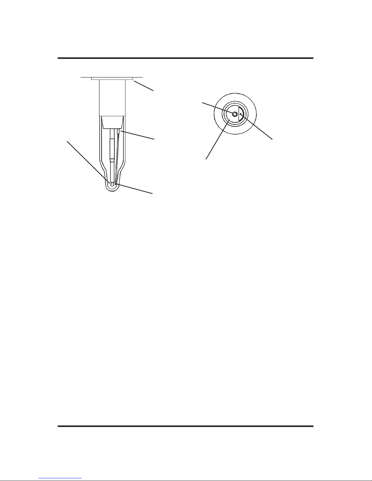
78
The Advanced®Osmometer Model 3900 User’s Guide
A. The tip of the probe must be in the center of the sample tube, an equal dis-
tance from all surfaces. The probe tip must be the same distance from the
bottom of the tube as it is from the side walls.
B. The flange of the mandrel must be flush with the head chassis.
C. The stir/freeze wire should be 1-1.5 mm, (1/32-1/16”) away from the man-
drel at this point. See bottom view.
D. The stir/freeze wire should be about 1 mm (1/32”) away from the probe.
Bend the wire where it changes diameter if necessary.
MANDREL BOTTOM VIEW
PROBE
MANDREL
STIR WIRE
A
B
C
D
Figure 11: Mandrel, Probe, and Stir Wire Adjustment
Page 97

79
Troubleshooting Table
Appendix A
Abrupt loss
of power (no
display)
1. Power availability.
Temporarily unplug the
power cord from its wall
outlet and replace it with
a known workable lamp
or small appliance.
2. Power connection.
3. Unplug the power cord
from the power cord
socket. Use a small
screwdriver to pry out
the voltage selector/fuse
holder. Visually check
the two 5 mm x 20 mm
time delay (T) fuses
mounted on it. Use a
continuity checker, or
replacement fuse to
check continuity if there
is any doubt.
Check the values
marked on the fuses. For
100-130V operation
they should be 2-Amp
fuses; for 200-250V
operation they should be
1-Amp fuses.
Symptom
Check
Suggested Action
1. Have the power restored.
2. Make sure the power
cord is firmly plugged
into both the wall outlet
and the socket on the
back of the instrument.
3. Replace the fuses if
blown or if incorrect
value.
Reinstall the fuse holder
into the back of the
instrument with the correct arrowheads matching.
If the fuses were blown
and the replacement fuses
blow also, see Chapter 5
for further assistance.
Page 98

The Advanced®Osmometer Model 3900 User’s Guide
80
“Block Probe
Failure”
“Block Probe
Open?”
“Calibration
Out of Range;
Repeat Calib”
“Calibrator Out
of Range”
“Cassette Index
Error”
“Cassette
Pusher Not
Back”
“Check
Calibration”
Switch the instrument off,
then on
Check the sample probe
by running the A/D Test.
Switch the instrument off,
then on.
Check the sample probe
by running the A/D Test.
Procedure, technique.
Wrong calibrator? See
Chapter 4.
Visually check for a cassette in the wrong position
or other visible mechanical cause.
Reported when “buzz”
point is changed. Buzz
setting can change calibration.
Symptom
Check
Suggested Action
If the problem persists, see
Chapter 5 for further assistance.
If the problem persists, see
Chapter 5 for further assistance.
Repeat calibration.
Repeat calibration.
1. Clear the cause of the
problem, if visible, and
properly realign all
remaining cassettes
before continuing.
2. Press STOP to reset the
instrument.
3. Press START to continue
testing.
If the problem persists, see
Chapter 5 for further assistance.
Recalibrate with new buzz
point.
Page 99

81
Troubleshooting Table
“Cooling
System Error”
“Duplicate
Cassette #”
“EPROM
Failure”
“Event Record
Lost”
“Fluid Level =
Error”
“Fluid
Required”
“Full Deck”
Switch the instrument off,
then on.
Cassette. Cassettes cannot
be reintroduced during
Batch or Bar Code runs.
Switch the instrument off,
then on.
Switch the instrument off,
then on.
Check whether further
testing is being impeded
by too many tested cassettes remaining in the
right (output) cassette
deck. Sensor is located in
front right side.
Symptom
Check
Suggested Action
Retry the test.
If the problem persists, see
Chapter 5 for further assistance.
Use a cassette not previously used in this run, or
start another batch.
If the problem persists, see
Chapter 5 for further assistance.
If the problem persists, see
Chapter 5 for further assistance.
A wiring or circuit board
error is indicated.If the
problem persists, see
Chapter 5 for further assistance.
Add heat transfer fluid. If
the problem persists, see
Chapter 5 for further assistance.
1. Remove some of the tested cassettes from the
right cassette deck, especially the front.
2. At “Press START to
Continue”, press START
to resume testing.
Page 100

82
The Advanced®Osmometer Model 3900 User’s Guide
“Head Not Up”
or “Head Not
Down”
“Head Rotation
Error”
“Illegal Error
Code”
Switch the instrument off,
then on.
Check the operating head
alignment by running the
Head Up/Down Test.
Check the probe and
stir/freeze wire alignment.
Visually check for a sample tube stuck on the mandrel, or other similar
mechanical cause.
Switch the instrument off,
then on.
Symptom
Check
Suggested Action
Realign the probe and stir/
freeze wire as necessary.
If the problem persists, see
Chapter 5 for further assistance.
1. Clear and discard the
stuck sample tube or
other visible cause of the
malfunction.
2. Check that the probe and
stir/freeze wire are still in
proper position.
3. Press STOP to reset the
instrument.
4. Remove the interrupted
cassette. To finish testing
it, remove already tested
samples and place the
cassette all the way to the
left in the input deck.
5. Press START to continue
testing. If the problem
recurs, see Chapter 5 for
further assistance.
Retry the test.
If the problem persists, see
Chapter 5 for further assistance.
 Loading...