

Advanced Hardware Architectures AHA4012B-006PJI, AHA4012B-006PJC Datasheet

Pr oduct Specification
AHA4012B
1.5 MBytes/sec Reed-Solomon
Error Correction Device
Advanced Hardware
Architectures, Inc.
2365 NE Hopkins Court
Pullman, WA 99163-5601
509.334.1000
Fax: 509.334.9000
e-mail: sales@aha.com
http://www.aha.com
TM
Advanced Hardware
Architectures
The Data Coding Leader
PS4012B-0100

Table of Contents
Advanced Hardware Architectures, Inc.
1.0 Introduction
1.1 Features . . . . . . . . . . . . . . . . . . . . . . . . . . . . . . . . . . . . . . . . . . . . . . . . . . . . . . . . . . . . . . . . . . . . . . . . . . . . .1
1.2 Conventions, Notations and Definitions . . . . . . . . . . . . . . . . . . . . . . . . . . . . . . . . . . . . . . . . . . . . . . . . . . . . .1
1.2.1 Definition of Correction Terms . . . . . . . . . . . . . . . . . . . . . . . . . . . . . . . . . . . . . . . . . . . . . . . . . . . . . . .2
2.0 Functional Description
2.1 Functional Overview . . . . . . . . . . . . . . . . . . . . . . . . . . . . . . . . . . . . . . . . . . . . . . . . . . . . . . . . . . . . . . . . . . .2
2.2 Correcting Capability and Polynomials. . . . . . . . . . . . . . . . . . . . . . . . . . . . . . . . . . . . . . . . . . . . . . . . . . . . . .3
2.3 Signal Descriptions. . . . . . . . . . . . . . . . . . . . . . . . . . . . . . . . . . . . . . . . . . . . . . . . . . . . . . . . . . . . . . . . . . . . .4
2.4 Pinout . . . . . . . . . . . . . . . . . . . . . . . . . . . . . . . . . . . . . . . . . . . . . . . . . . . . . . . . . . . . . . . . . . . . . . . . . . . . . . .5
2.5 Data Flow . . . . . . . . . . . . . . . . . . . . . . . . . . . . . . . . . . . . . . . . . . . . . . . . . . . . . . . . . . . . . . . . . . . . . . . . . . . .5
2.5.1 Shortened Blocks . . . . . . . . . . . . . . . . . . . . . . . . . . . . . . . . . . . . . . . . . . . . . . . . . . . . . . . . . . . . . . . . .5
2.6 Reset and Initialization Sequence. . . . . . . . . . . . . . . . . . . . . . . . . . . . . . . . . . . . . . . . . . . . . . . . . . . . . . . . . .6
2.6.1 Initialization Registers. . . . . . . . . . . . . . . . . . . . . . . . . . . . . . . . . . . . . . . . . . . . . . . . . . . . . . . . . . . . . .6
2.7 Encode, Decode or Pass-through Operations . . . . . . . . . . . . . . . . . . . . . . . . . . . . . . . . . . . . . . . . . . . . . . . .7
2.8 Buffers. . . . . . . . . . . . . . . . . . . . . . . . . . . . . . . . . . . . . . . . . . . . . . . . . . . . . . . . . . . . . . . . . . . . . . . . . . . . . . .8
2.9 Data Rate and Latencies. . . . . . . . . . . . . . . . . . . . . . . . . . . . . . . . . . . . . . . . . . . . . . . . . . . . . . . . . . . . . . . .8
2.9.1 Burst Operation . . . . . . . . . . . . . . . . . . . . . . . . . . . . . . . . . . . . . . . . . . . . . . . . . . . . . . . . . . . . . . . . . .8
2.9.2 Continuous Operation. . . . . . . . . . . . . . . . . . . . . . . . . . . . . . . . . . . . . . . . . . . . . . . . . . . . . . . . . . . . . .9
2.10 Reed-Solomon (ECC) Module and Error Rate Performance . . . . . . . . . . . . . . . . . . . . . . . . . . . . . . . . . . . .11
2.11 Determining Decoder Performance Boundaries. . . . . . . . . . . . . . . . . . . . . . . . . . . . . . . . . . . . . . . . . . . . . .12
2.12 Erasures . . . . . . . . . . . . . . . . . . . . . . . . . . . . . . . . . . . . . . . . . . . . . . . . . . . . . . . . . . . . . . . . . . . . . . . . . . . .12
3.0 Operational Description
3.1 Clock. . . . . . . . . . . . . . . . . . . . . . . . . . . . . . . . . . . . . . . . . . . . . . . . . . . . . . . . . . . . . . . . . . . . . . . . . . . . . . .12
3.2 Initialization. . . . . . . . . . . . . . . . . . . . . . . . . . . . . . . . . . . . . . . . . . . . . . . . . . . . . . . . . . . . . . . . . . . . . . . . . .13
3.3 Data Input . . . . . . . . . . . . . . . . . . . . . . . . . . . . . . . . . . . . . . . . . . . . . . . . . . . . . . . . . . . . . . . . . . . . . . . . . . .13
3.4 Data Output. . . . . . . . . . . . . . . . . . . . . . . . . . . . . . . . . . . . . . . . . . . . . . . . . . . . . . . . . . . . . . . . . . . . . . . . . .14
. . . . . . . . . . . . . . . . . . . . . . . . . . . . . . . . . . . . . . . . . . . . . . . . . . . . . . . . . . . . . . . . . . . . . . . . . . . . . .1
. . . . . . . . . . . . . . . . . . . . . . . . . . . . . . . . . . . . . . . . . . . . . . . . . . . . . . . . . . . . . . . . . . . . .2
. . . . . . . . . . . . . . . . . . . . . . . . . . . . . . . . . . . . . . . . . . . . . . . . . . . . . . . . . . . . . . . . . . .12
4.0 Signal Specifications
4.1 Input Specifications. . . . . . . . . . . . . . . . . . . . . . . . . . . . . . . . . . . . . . . . . . . . . . . . . . . . . . . . . . . . . . . . . . . .16
4.2 Output Specifications . . . . . . . . . . . . . . . . . . . . . . . . . . . . . . . . . . . . . . . . . . . . . . . . . . . . . . . . . . . . . . . . . .16
4.3 Power & Ground Pins . . . . . . . . . . . . . . . . . . . . . . . . . . . . . . . . . . . . . . . . . . . . . . . . . . . . . . . . . . . . . . . . . .17
4.4 AC Electrical Characteristics. . . . . . . . . . . . . . . . . . . . . . . . . . . . . . . . . . . . . . . . . . . . . . . . . . . . . . . . . . . . .17
4.5 DC Electrical Characteristics . . . . . . . . . . . . . . . . . . . . . . . . . . . . . . . . . . . . . . . . . . . . . . . . . . . . . . . . . . . .18
5.0 Packaging
6.0 Ordering Information
6.1 Available Parts . . . . . . . . . . . . . . . . . . . . . . . . . . . . . . . . . . . . . . . . . . . . . . . . . . . . . . . . . . . . . . . . . . . . . . .19
6.2 Part Numbering. . . . . . . . . . . . . . . . . . . . . . . . . . . . . . . . . . . . . . . . . . . . . . . . . . . . . . . . . . . . . . . . . . . . . . .20
7.0 Related Technical Publications
Appendix A
Appendix B
. . . . . . . . . . . . . . . . . . . . . . . . . . . . . . . . . . . . . . . . . . . . . . . . . . . . . . . . . . . . . . . . . . . . . . . . . . . . . . .19
. . . . . . . . . . . . . . . . . . . . . . . . . . . . . . . . . . . . . . . . . . . . . . . . . . . . . . . . . . . . . . . . . . . . . . . . . . . . . . . . .21
. . . . . . . . . . . . . . . . . . . . . . . . . . . . . . . . . . . . . . . . . . . . . . . . . . . . . . . . . . . . . . . . . . . . . . . . . . . . . . . . .23
. . . . . . . . . . . . . . . . . . . . . . . . . . . . . . . . . . . . . . . . . . . . . . . . . . . . . . . . . . . . . . . . . . . . .16
. . . . . . . . . . . . . . . . . . . . . . . . . . . . . . . . . . . . . . . . . . . . . . . . . . . . . . . . . . . . . . . . . . . . . .19
. . . . . . . . . . . . . . . . . . . . . . . . . . . . . . . . . . . . . . . . . . . . . . . . . . . . . . . . . . . . .20
PS4012B-0100
i

Advanced Hardware Architectures, Inc.
Figures
Figure 1: Block Diagram. . . . . . . . . . . . . . . . . . . . . . . . . . . . . . . . . . . . . . . . . . . . . . . . . . . . . . . . . . . . . . . . . . . . . .3
Figure 2: Typical Applications Diagram . . . . . . . . . . . . . . . . . . . . . . . . . . . . . . . . . . . . . . . . . . . . . . . . . . . . . . . . . .4
Figure 3: Pinout . . . . . . . . . . . . . . . . . . . . . . . . . . . . . . . . . . . . . . . . . . . . . . . . . . . . . . . . . . . . . . . . . . . . . . . . . . . .5
Figure 4: Data Input and Output Order. . . . . . . . . . . . . . . . . . . . . . . . . . . . . . . . . . . . . . . . . . . . . . . . . . . . . . . . . . .5
Figure 5: Burst and Continuous Operations. . . . . . . . . . . . . . . . . . . . . . . . . . . . . . . . . . . . . . . . . . . . . . . . . . . . . .10
Figure 6: Symbol (Byte) Error Rate Performance Curves for Codeword Length = 255 Bytes. . . . . . . . . . . . . . . .11
Figure 7: CLK Characteristics . . . . . . . . . . . . . . . . . . . . . . . . . . . . . . . . . . . . . . . . . . . . . . . . . . . . . . . . . . . . . . . .12
Figure 8: Reset and Initialization Timing . . . . . . . . . . . . . . . . . . . . . . . . . . . . . . . . . . . . . . . . . . . . . . . . . . . . . . . .13
Figure 9: Data Input - Input Buffer Always Ready . . . . . . . . . . . . . . . . . . . . . . . . . . . . . . . . . . . . . . . . . . . . . . . . .13
Figure 10: Data Input - Buffer Not Ready. . . . . . . . . . . . . . . . . . . . . . . . . . . . . . . . . . . . . . . . . . . . . . . . . . . . . . . . .14
Figure 11: Data Output. . . . . . . . . . . . . . . . . . . . . . . . . . . . . . . . . . . . . . . . . . . . . . . . . . . . . . . . . . . . . . . . . . . . . . .14
Figure 12: CRTN Timing . . . . . . . . . . . . . . . . . . . . . . . . . . . . . . . . . . . . . . . . . . . . . . . . . . . . . . . . . . . . . . . . . . . . .15
ii
PS4012B-0100

Advanced Hardware Architectures, Inc.
Tables
Table 1: Initialization Register Settings for Encode, Decode and Pass-Through Operations. . . . . . . . . . . . . . . . .7
Table 2: Burst Operation Using 6 MHz Clock and 1 Clock/Byte . . . . . . . . . . . . . . . . . . . . . . . . . . . . . . . . . . . . . . .9
Table 3: Continuous Operation Using 6 MHz Clock and Specified Clocks/Byte. . . . . . . . . . . . . . . . . . . . . . . . . .10
Table 4: Continuous Operation for IESS-308 Codes Using 6 MHz Clock and Specified Clocks/Byte . . . . . . . . .10
PS4012B-0100
iii

Advanced Hardware Architectures, Inc.
1.0 INTRODUCTION
The AHA4012B is a single chip integrated
circuit that implements a Reed-Solomon Forward
Error Correction alg ori thm. The AHA4012B is the
lowest cost member of the AHA PerFEC family
of forward error correction (FEC) devices
conforming to the Intelsat IE S S- 308 specific ation.
Data flow through the devic e can occur in bursts at
6 MBytes per second or contin uous at 1.5 MBytes
per second maximum.
The device supports several programmable
parameters, including; block size, error threshold,
number of check bytes and mode of operations.
Shortened blocks are supported without requirement of zero padding. The dat a input port is u sed to
initialize the progr ammable parameters a nd the two
on-chip buffers are used to input and output data.
Discontinuities in data flow may be controlled by
dedicated control pins.
High operating frequenc y, in put and output data
rate flexibility, low processing latency and various
programmable parameters make this device ideal
for many applications including: DTV, DBS,
ADSL, Satellite Communications, ISDN, High
Performance Modems and networks.
This specification provides full electrical and
mechanical information to help a system engineer
develop a system using AHA401 2B. This document
contains descriptions on correction terms, pinout,
functions and featu res , DC and AC ch ar acteristics,
package and mechanical specifications, ordering
information and Related Technical Publications.
Software simulat ion of the RS code as implemented
in the device is also available. Please contact AHA
or its authorized sa les representatives worldwide for
copies of Related Technical Publications and
software simula t io n.
1.1 FEATURES
PERFORMANCE:
• Polynomial complies to Int elsat IESS-308;
RTCA DO-217 Appendix F, Revision D and
proposed ITU-TS SG-18 (Formerly CCITT SG-
18) Standards
• 6 MBytes/sec burst transfer rate with a 6 MHz
clock for all block lengths
• Maximum channel rate of 1.5 MBytes/sec
continuous for block lengths from 54 bytes
through 255 bytes using a 6 MHz clock
• Processi n g latency tim e less than 101 µsec in
continuous operation for block lengths of 100
bytes
FLEXIBILITY:
• Programmable to correc t fro m 1 to 10 error by tes
or 20 erasure bytes per block
• Block lengths programmable from 3 to 255 bytes
• Encode, decode or pass-through capabi li ty inline with data flow
• Continuous or burst mode operation
• Programm a ble error th re shold to help determine
channel performance
SYSTEM INTERFAC E:
• Byte wide synchronous I/O ports with internal
buffering on both ports
• Input data pins used for programmable
parameters
• Dedicated control pins permit discontinuities in
system data flow
OTHERS:
• 44 pin PLCC; 50 mil lead pitch
• Pin and plug compatible with the higher
performance AHA4011
• Software emulation of the algorithm available
1.2 CONVE NTIONS, NOTATIONS AND
DEFINITIONS
– Certain signals are logically true at a voltage
defined as “low” in the dat a sheet. All such signals
have an “N” appended to the end of the signal
name. For example, RSTN and DSON.
– “Signal assertion” means the output signal is
logically true.
– Hex values are defined with a pr efix of “0x” , such
as “0x10”.
– A range of signal names is denoted by a set of
colons between t he number s. Most sign ific ant bi t
is always shown first, followed by least significan t
bit. For example, DI[7:0] represents Data Input
Bus 7 through 0.
– A product of two variables is expressed with an
“×”, for example, N × C
Length multiplied by Input clocks/byte.
– Mega Bytes per second is referred to as MBytes/
sec or MB/sec.
– Channel Rate is defined as transfer rate includi ng
user data and error correction check bytes.
represents Codeword
i
PS4012B-0100 Page 1 of 24
Advanced Hardware Architectures, Inc.
1.2.1 DEFINITION OF CORRECTION T E RMS
TERM
NAME
(other references)
Message Length
K
(user data or message
bytes)
Check symbols
R
(parity or redundan cy)
Codeword Length
N
(block lengt h)
t Error Corrections
P Error Threshold
e Number of Errors
E Number of Erasures
G Burden of Correction
DEFINITION
Number of user data symbols in one message bloc k.
Size of a symbol in AHA4012B is 8-bits. Message
length is K = N − R. The first message byte is
referred to as X
Symbols appended to the user data to detect and
correct errors. The number of check symbols
required in a system is R ≤ E + 2e.* The first check
symbol is referred to as Y
.
is Y
0
Sum of message and check symbols. N = K + R.
Maximum number of error corrections performed
by the device. The value is t = Integer .
The threshold limit to determine uncorrectability
of a Codeword and the number of check bytes
allocated for correct io n-only pur po ses (not for
detection).
An error is defined as an erroneous byte whose
correct value and position within the message
block are both unknown.
An erasure is defined as a n error whose posi tion is
known within the message block.**
A measure of the bur den of correction bein g placed
on the capabilities of the device for that message
block. The value G = 2e + E.
; the last message byte is X0.
K−1
; the last check symbol
R−1
NK–
-------------2
RANGE
(number of bytes)
1 through 253
(1, 2, 3, 4 . . . 253)
2 through 20 in
increments of 1
(2, 3, 4 . . . 20)
3 through 255
(3, 4, 5, 6 . . . 255)
1 through 10
(1, 2, 3 . . . 10)
2 through 20
(2, 3, 4 . . . 20)
0 through N
0 through N
0 through R
* For every 2 check bytes, the AHA4012B can correct either 2 erasures or 1 error.
** An erasure is detected by a parity detector or a signal dropout detector. The presence of an erasure is
indicated by asserting the ERASE signal when the erased byte is clocked into the AHA4012B.
2.0 FUNCTIONAL DESCRIPTION
This section describes an architectural
overview of the chip and its many functions,
features and operating modes. The block diagram
for the chip sh ows the Reed-Solomon ECC mod ule,
the Input and Output Buffers and their associated
control. All input an d output data are cl ocked on the
rising edge of CLK.
2.1 FUNCTIONAL OVERVIEW
The AHA4012B Reed-Solomon codec (coder/
decoder) is the lowest cost member of the AHA
PerFEC
devices. This single chip, three-layer metal, CMOS
device can operate in encode, decode or passthrough modes.
TM
family of forward error correction (FEC)
The ECC core imp lements a full err or
correcting R eed-Solomon decoder. This code is
capable of correct ing up to 10 (t = 10 ) byte-errors or
20 (t = 10) erasures in a block.
Page 2 of 24 PS4012B-0100
Advanced Hardware Architectures, Inc.
R
# erasures 2 # errors()+≥
The ECC core has three phases of operation:
Data In, Calculation and Data Out. Data to be
processed is first input into a singl e po rted Input
Buffer using a control signal DSIN. ECC core
arbitrates fo r the input data out of th e Input Buffer.
ECC core has access to the Input Buffer on clock
edges where DSIN is not asserted.
Each block is processed within the ECC core
and calculations are made. The entire block is
processed through the ECC core and transferred
into the Output Buf fer. The device asserts RDYON
signal and holds active until the Output Buffer is
completely emptied.
The ECC core loads the Output Buffer in
reverse order fo r either mode. Da ta is strobed o ut of
the device in forward order.
The use of internal buffers is restricted per the
rules defined in Section 2.9
Latencies
.
Data Rate and
Maximum delay required for each block of a
given length to pass thr ough the de vice is fixed and
does not vary with the location or the number of
errors received. This delay (or latency), expressed
in the number of clocks is discussed in a later
section.
2.2 CORRECTING CAPABILITY AND
P OLYNOMIALS
For every 2 check bytes, the de c oder corrects
either 2 erasures or 1 error. An erasure can be
determined with a parity detector or a signal dropout
detector external to the chip. An erasure is indicated
by the ERASE signal when the erased byte is
clocked into the device.
Correcting “erasures” takes only half as much
of the correction capa bility of the RS code as it takes
to correct “err ors”, since the p osition informat ion is
already known for “er asures”. The correction abil ity
of the code is bounded as:
Valid block length (N) is defined by the
relationship:
1
R
255≤≤+
N
where R ranges from 2 to 20.
A complete codeword can therefore ra nge from
a minimum of 3 to a maximum of 255 bytes.
For further discussion on error rate
performance, refer to Section 2.10
(ECC) Module and Error Rate Performa nce
Reed-Solomon
.
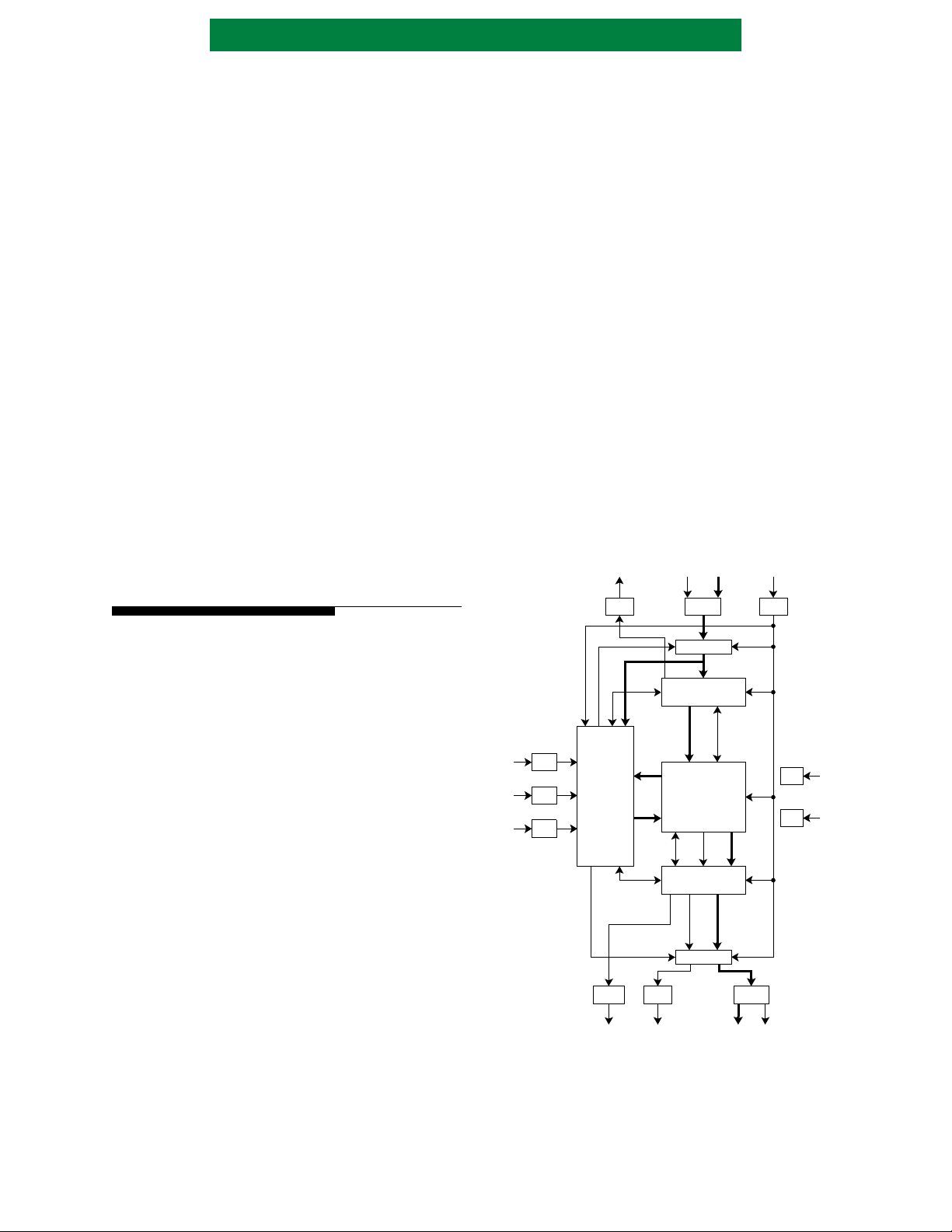
Figure 1: Block Diagram
RDYIN
RDYIN CLK
ERASE DI[7:0] CLK
DI
Compared w ith other codes , RS codes require
relatively few “overhead” check bytes to be added
to the data stream to achieve a high degree of er ror
detection and correction. Since the AHA4012B
deals with bytes (or symbols) rather than with
individual bits, when a byte is in error it does not
matter how many bits within the byt e are corrupted;
it is counted as one error.
The Reed-Solomon code is defined over the
finite field GF(28). The field defining primitive
polynomial is:
Px()x8x7x2x
1++++=
and the generator polynomial , dep endent on the
variable R, is given by:
119R+
()
Gx
=
∏
i
αi–()
x
120=
where R {2, 3, 4, 5, . . . 20} for the AHA4012B.
This polynomial is specifie d in international
standards, Intelsat IESS-308; RTCA DO-217
Appendix F, Revision D and the proposed ITU-TS
SG-18 (Formerly CCITT SG-18).
REGISTER
INPUT BUFFER
367x9
RSTN
RSTN
DSIN
DSON
DSIN
DSON
CONTROL
RDYON
RDYON CRTN DO[7:0] ERR
ECC CORE
OUTPUT BUFFER
REGISTER
CRTN
256x9
DO
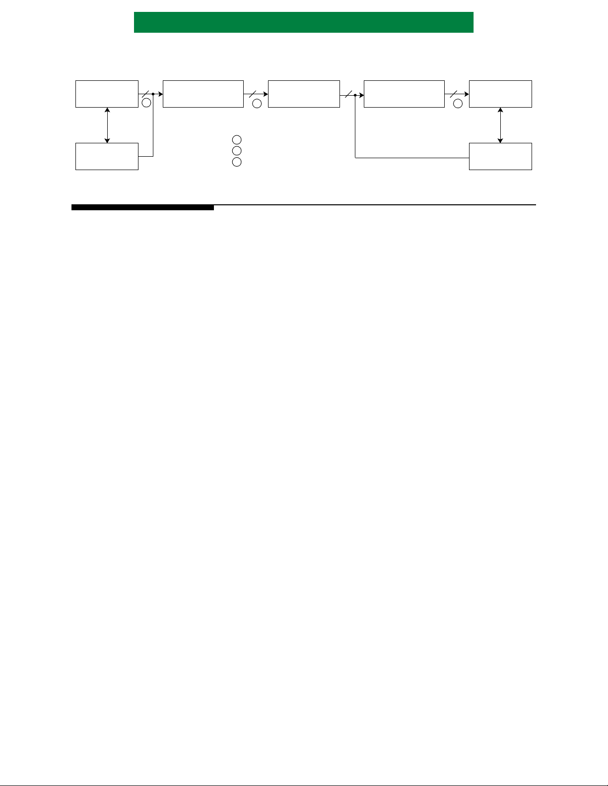
A typical system bloc k diagram is shown in the
following figure.
GND
VDD
GND
VDD
PS4012B-0100 Page 3 of 24
Advanced Hardware Architectures, Inc.
Figure 2: Typical Applications Diagram
ENCODER COMMUNICATIONS DECODER
DATA SOURCE
SYSTEM
CONTROLLER
8 8 8 8
A
AHA4012B
ECC COPROCESSOR
BLOCK FORMAT AT:
A
B
C
B C
KDATA PLUS R “DUMMY” BYTES
KDATA PLUS R CHECK BYTES
KDATA BYTE S
2.3 SIGNAL DESCRIPTIONS
CHANNEL
1 TO x BITS WIDE
AHA4012B
ECC COPROCESSOR
DATA SINK
SYSTEM
CONTROLLER
Input Pins
DI[7:0] Data Input Bus. The input byte and ERASE
are latched on the rising edge of the clock
when both DSIN and RDYIN are active. I f
either DSIN or RDYIN are inactive, the DI
and ERASE are ignored.
DSIN Data Input Strobe. Enables data from DI to
be loaded into the chip. When RDYIN is
active, DSIN being active on the rising
edge of the cl ock loads the input data i n the
device. DSIN must be activ e for o ne c lock
edge only per each input byte. DSIN is
ignored if RDYIN is inactive. Signal is
active low.
DSON Data Output Strobe. This input strobe
acknowledges to the chip that data
available on the Outpu t Bus, DO, has be en
received by the system. The device uses
this strobe to increment its internal address
counter to the next data location. DSON
must be active for one clock edge only p er
each output byte. DSON is ignored if
RDYON is inactive. Active low.
ERASE Erasure input flag fo r symbol currently on
DI. Signal is active high. ERASE signal is
used for marking all check Bytes as
erasures (dummy check Bytes) during
encode operation. It is also used to mark
input symbols that contain errors during
decoding. If not used, conn ect this signal to
ground.
RSTN Reset. Input pi n. When RSTN is active and
DSIN and DSON are inactive, the device
forces all internal control circuitry into a
known state and initializes all data path
elements. RSTN is active during
Initialization Phase. In this phase, chip
parameters are programmed by using DI
and DSIN. Signal is active low.
CLK Clock. System clock input. Refer to
Section 4.4
for clock requirements.
AC Electrical Characteristics
Output Pins
RDYIN Ready Input. Indicates the chip's abili t y to
accept data input on DI. If ac tive, DSIN is
allowed to enable the loading of input data
on DI. When inactive, DSIN is ignored.
Signal is active low.
DO[7:0] Data Output. The output byte is available
on this bus. The val ue of the outpu t byte is
undefined if RDYON is inactive. Requ ires
an acknowledge strobe, DSON, at a rising
edge of the clock to increment internal
address counter and output the next
location in the buffer. DO bus is al w ays
driven and is not tristated by the device.
R D Y O NReady Output. This output pin indicates the
chip's abil ity to gener ate output data. If
active, DSON is allowed to increment the
internal address counter for the next data
byte. When inactive DSON is ignored and
DO is undefined. Signal is active low.
CRTN Correctable. The output pin when active
indicates the blo ck did not exceed th e error
threshold programmed by P. Error
threshold must be programmed with the
same value as the number of chec k symbols
R if erasures are not used. This signal is
valid when the first mess age byte , X
the block is available out of the chip.
During all other times the signal is
undefined. Signal is valid for at least one
clock. Active low.
ERR Error. Output pin indicates the current
value on DO[7:0] is a corrected byte.
Active high.
K−1
, of
Page 4 of 24 PS4012B-0100
Advanced Hardware Architectures, Inc.
2.4 PINOUT
Figure 3: Pinout
INPUT
DI0
DI1
DI2
DI3
65432
7
VDD
8
GND
9
VDD
10
GND
11
GND
12
VDD
13
*NC
*NC
VDD
GND
GND
AHA4012B-006 PJC
14
15
16
17
1819202122232425262728
DO0
DO1
DO2
DO3
OUTPUT
*NC = No connect, reserved for future considerations.
2.5 DATA FLOW
DI4
DI5
DI6
1
4443424140
DO4
DO5
DO6
DI7
DISN
TM
DO7
VDD
CLK
ERR
GND
CRTN
39
38
37
36
35
34
33
32
31
30
29
VDD
VDD
GND
VDD
RSTN
ERASE
DSON
RDYIN
RDYON
GND
GND
device requires reinitialization only when the
parameters are changed or a reset is required.
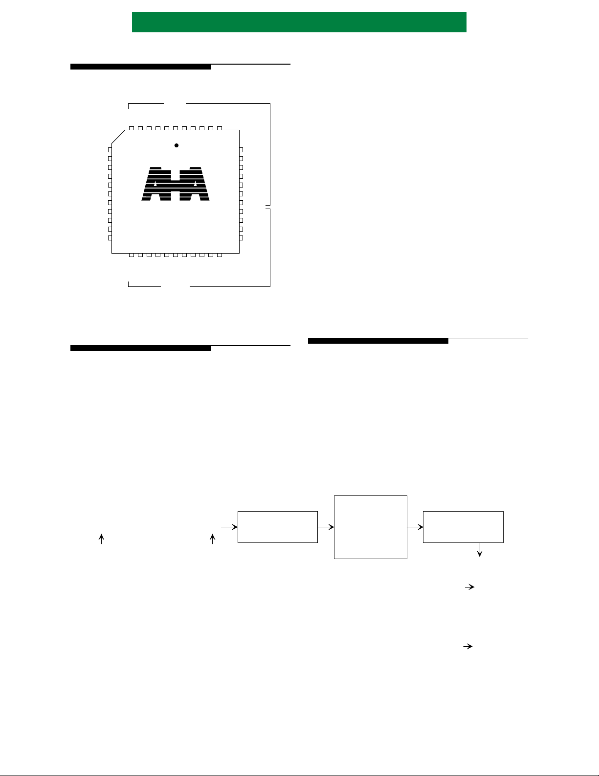
The device processes data as “blocks”
containing Message and Check Bytes. Order of
input bytes must be f irst message byte X
last message byte X
through last check byte Y0. The device
Y
R−1
, followed by first check byte
0
through
K−1
contains an internal counter to keep track of start
and end of block. No external signal is required to
indicate start and end of block. The device processes
the block in this manner:
- a block is clocked into the Input Buffer;
- transferred into the ECC module ;
- passed to t he Output Buffer in the reverse order
from what was received at the Input Port; and
- clocked out through the Output Port via the
Output Buffer. Consecutive blocks may be
input into the Input Buffer while the Output
Buffer is be ing emptied.
Data is available through the Output Port in
forward order . Data is clocked out in the same order
as it is input.
2.5.1 SHORTENED BLOCKS
The device is first initialized for various
programmable parameters including: Erasure
Multiplier, Error Threshold, Number of Check
bytes, Number of Message bytes per block, Block
Length and a Control byte. Following t his six-byte
initialization, the device may be used to encode,
decode or pass-through multiple blocks of data. The
Figure 4: Data Input and Output Order
. . . . . .
Y1Y
0
Last
Byte
In
X
Y
X
1
0R-2YR-1
X
K-2XK-1
First
Byte
In
INPUT
BUFFER
This device allows for shortened RS blocks,
thus not requiring zero padding when decoding.
During encoding, converseley, zero padding is not
performed. When the device is programmed to
decode a block of less than 244 Bytes, only the
message Bytes followed by check Bytes are sent.
Prepending with zero value Bytes to fill out the
block to 255 Bytes is not required.
ECC
Core
OUTPUT
BUFFER
Data Available
Forward Order
Last Byte Out
First Byte Out
Y
0
.
.
.
Y
R-1
X
0
.
.
.
X
K-1
PS4012B-0100 Page 5 of 24
 Loading...