


PRELIMINARY *
Product Specification
AHA3580
80 MBytes/sec ALDC Data
Compression Coprocessor IC
2365 NE Hopkins Court
Pullman, WA 99163-5601
tel: 509.334.1000
fax: 509.334.9000
e-mail: sales@aha.com
www.aha.com
advancedhardwarearchitectures
* This specification represents a product still in the design cycle, undergoing testing processes, any specifications
are based on design goals only. Parameters may be subject to change pending completion of characterization.
PS3580-1100

Advanced Hardware Architectures, Inc.
Table of Contents
1.0 Introduction . . . . . . . . . . . . . . . . . . . . . . . . . . . . . . . . . . . . . . . . . . . . . . . . . . . . . . . . . . . . . . . . . . . . . . . . . . . . .1
1.1 Conventions, Notations and Definitions. . . . . . . . . . . . . . . . . . . . . . . . . . . . . . . . . . . . . . . . . . . . . . . . . . . . .1
1.2 Features . . . . . . . . . . . . . . . . . . . . . . . . . . . . . . . . . . . . . . . . . . . . . . . . . . . . . . . . . . . . . . . . . . . . . . . . . . . .1
1.3 Applications. . . . . . . . . . . . . . . . . . . . . . . . . . . . . . . . . . . . . . . . . . . . . . . . . . . . . . . . . . . . . . . . . . . . . . . . . .1
1.4 Functional Description. . . . . . . . . . . . . . . . . . . . . . . . . . . . . . . . . . . . . . . . . . . . . . . . . . . . . . . . . . . . . . . . . .2
1.4.1 Port A and Port B Interfaces. . . . . . . . . . . . . . . . . . . . . . . . . . . . . . . . . . . . . . . . . . . . . . . . . . . . . . .3
1.4.1.1 FAS466 DMA Mode. . . . . . . . . . . . . . . . . . . . . . . . . . . . . . . . . . . . . . . . . . . . . . . . . . . . . . .3
1.4.1.2 Initiator Synchronous DMA Mode . . . . . . . . . . . . . . . . . . . . . . . . . . . . . . . . . . . . . . . . . . . .3
1.4.2 Data Expansion During Compression . . . . . . . . . . . . . . . . . . . . . . . . . . . . . . . . . . . . . . . . . . . . . . .4
1.4.3 Multiple Records. . . . . . . . . . . . . . . . . . . . . . . . . . . . . . . . . . . . . . . . . . . . . . . . . . . . . . . . . . . . . . . .4
1.4.4 Byte Alignment. . . . . . . . . . . . . . . . . . . . . . . . . . . . . . . . . . . . . . . . . . . . . . . . . . . . . . . . . . . . . . . . .4
2.0 Compression Operation . . . . . . . . . . . . . . . . . . . . . . . . . . . . . . . . . . . . . . . . . . . . . . . . . . . . . . . . . . . . . . . . . . .5
2.1 Compression Pass Through . . . . . . . . . . . . . . . . . . . . . . . . . . . . . . . . . . . . . . . . . . . . . . . . . . . . . . . . . . . . .5
2.2 Compression. . . . . . . . . . . . . . . . . . . . . . . . . . . . . . . . . . . . . . . . . . . . . . . . . . . . . . . . . . . . . . . . . . . . . . . . .5
3.0 Decompression Operation . . . . . . . . . . . . . . . . . . . . . . . . . . . . . . . . . . . . . . . . . . . . . . . . . . . . . . . . . . . . . . . . .6
3.1 Decompression Pass Through . . . . . . . . . . . . . . . . . . . . . . . . . . . . . . . . . . . . . . . . . . . . . . . . . . . . . . . . . . .6
3.2 Decompression . . . . . . . . . . . . . . . . . . . . . . . . . . . . . . . . . . . . . . . . . . . . . . . . . . . . . . . . . . . . . . . . . . . . . . .6
3.3 Decompression Output Disabled Mode. . . . . . . . . . . . . . . . . . . . . . . . . . . . . . . . . . . . . . . . . . . . . . . . . . . . .6
4.0 Microprocessor Interface and Register Access . . . . . . . . . . . . . . . . . . . . . . . . . . . . . . . . . . . . . . . . . . . . . . . .6
4.1 Microprocessor Interface. . . . . . . . . . . . . . . . . . . . . . . . . . . . . . . . . . . . . . . . . . . . . . . . . . . . . . . . . . . . . . . .6
4.1.1 Interrupts . . . . . . . . . . . . . . . . . . . . . . . . . . . . . . . . . . . . . . . . . . . . . . . . . . . . . . . . . . . . . . . . . . . . .6
4.1.2 Resets . . . . . . . . . . . . . . . . . . . . . . . . . . . . . . . . . . . . . . . . . . . . . . . . . . . . . . . . . . . . . . . . . . . . . . .7
4.1.3 Port A Interface FIFO Access. . . . . . . . . . . . . . . . . . . . . . . . . . . . . . . . . . . . . . . . . . . . . . . . . . . . . .7
4.2 Register Access. . . . . . . . . . . . . . . . . . . . . . . . . . . . . . . . . . . . . . . . . . . . . . . . . . . . . . . . . . . . . . . . . . . . . . .8
4.3 Pausing / Resume. . . . . . . . . . . . . . . . . . . . . . . . . . . . . . . . . . . . . . . . . . . . . . . . . . . . . . . . . . . . . . . . . . . . .8
5.0 Port A and Port B Configuration. . . . . . . . . . . . . . . . . . . . . . . . . . . . . . . . . . . . . . . . . . . . . . . . . . . . . . . . . . . . .8
6.0 Register Description . . . . . . . . . . . . . . . . . . . . . . . . . . . . . . . . . . . . . . . . . . . . . . . . . . . . . . . . . . . . . . . . . . . . . .9
6.1 Status 0 (STAT0). . . . . . . . . . . . . . . . . . . . . . . . . . . . . . . . . . . . . . . . . . . . . . . . . . . . . . . . . . . . . . . . . . . . .10
6.2 Status 1 (STAT1). . . . . . . . . . . . . . . . . . . . . . . . . . . . . . . . . . . . . . . . . . . . . . . . . . . . . . . . . . . . . . . . . . . . .11
6.3 Port A Configuration 0 (ACNF0) . . . . . . . . . . . . . . . . . . . . . . . . . . . . . . . . . . . . . . . . . . . . . . . . . . . . . . . . .12
6.4 Port A Configuration 1 (ACNF1) . . . . . . . . . . . . . . . . . . . . . . . . . . . . . . . . . . . . . . . . . . . . . . . . . . . . . . . . .12
6.5 Port B Configuration 0 (BCNF0) . . . . . . . . . . . . . . . . . . . . . . . . . . . . . . . . . . . . . . . . . . . . . . . . . . . . . . . . .12
6.6 Port B Configuration 1 (BCNF1) . . . . . . . . . . . . . . . . . . . . . . . . . . . . . . . . . . . . . . . . . . . . . . . . . . . . . . . . .13
6.7 Identification (ID0, ID1) . . . . . . . . . . . . . . . . . . . . . . . . . . . . . . . . . . . . . . . . . . . . . . . . . . . . . . . . . . . . . . . .13
6.8 Port A Polarity (APOL). . . . . . . . . . . . . . . . . . . . . . . . . . . . . . . . . . . . . . . . . . . . . . . . . . . . . . . . . . . . . . . . .13
6.9 Port B Polarity (BPOL). . . . . . . . . . . . . . . . . . . . . . . . . . . . . . . . . . . . . . . . . . . . . . . . . . . . . . . . . . . . . . . . .14
6.10 Port A Transfer Count (ATCL0, ATCL1, ATCH0, ATCH1) . . . . . . . . . . . . . . . . . . . . . . . . . . . . . . . . . . . . .14
6.11 Record Count (RCL0, RCL1, RCH0, RCH1). . . . . . . . . . . . . . . . . . . . . . . . . . . . . . . . . . . . . . . . . . . . . . . .15
6.12 Port B Compare Count (BCCL0, BCCL1, BCCH0, BCCH1). . . . . . . . . . . . . . . . . . . . . . . . . . . . . . . . . . . .15
6.13 Port B Transfer Count (BTCL0, BTCL1, BTCH0, BTCH1) . . . . . . . . . . . . . . . . . . . . . . . . . . . . . . . . . . . . .16
6.14 Port A FIFO Data Access (AFIF0, AFIF1). . . . . . . . . . . . . . . . . . . . . . . . . . . . . . . . . . . . . . . . . . . . . . . . . .16
6.15 Compressed Bytes Processed (CBPL0, CBPL1, CBPH0, CBPH1) . . . . . . . . . . . . . . . . . . . . . . . . . . . . . .17
6.16 Port A FIFO Control (AFCT) . . . . . . . . . . . . . . . . . . . . . . . . . . . . . . . . . . . . . . . . . . . . . . . . . . . . . . . . . . . .17
6.17 Error Status (ERRS) . . . . . . . . . . . . . . . . . . . . . . . . . . . . . . . . . . . . . . . . . . . . . . . . . . . . . . . . . . . . . . . . . .18
6.18 Interrupt Status 0 (INTS0). . . . . . . . . . . . . . . . . . . . . . . . . . . . . . . . . . . . . . . . . . . . . . . . . . . . . . . . . . . . . .18
6.19 Interrupt Status 1 (INTS1). . . . . . . . . . . . . . . . . . . . . . . . . . . . . . . . . . . . . . . . . . . . . . . . . . . . . . . . . . . . . .19
6.20 Command (CMND) . . . . . . . . . . . . . . . . . . . . . . . . . . . . . . . . . . . . . . . . . . . . . . . . . . . . . . . . . . . . . . . . . . .20
6.21 Record Length (RLL0, RLL1, RLH0, RLH1) . . . . . . . . . . . . . . . . . . . . . . . . . . . . . . . . . . . . . . . . . . . . . . . .21
6.22 Data Disabled Count (DDCL0, DDCL1, DDCH0, DDCH1) . . . . . . . . . . . . . . . . . . . . . . . . . . . . . . . . . . . . .22
6.23 Error Mask (EMSK). . . . . . . . . . . . . . . . . . . . . . . . . . . . . . . . . . . . . . . . . . . . . . . . . . . . . . . . . . . . . . . . . . .22
PS3580-1100 i

Advanced Hardware Architectures, Inc.
6.24 Interrupt Mask 0 (IMSK0) . . . . . . . . . . . . . . . . . . . . . . . . . . . . . . . . . . . . . . . . . . . . . . . . . . . . . . . . . . . . . .23
6.25 Interrupt Mask 1 (IMSK1) . . . . . . . . . . . . . . . . . . . . . . . . . . . . . . . . . . . . . . . . . . . . . . . . . . . . . . . . . . . . . .23
7.0 Signal Descriptions . . . . . . . . . . . . . . . . . . . . . . . . . . . . . . . . . . . . . . . . . . . . . . . . . . . . . . . . . . . . . . . . . . . . . .24
7.1 Microprocessor Interface. . . . . . . . . . . . . . . . . . . . . . . . . . . . . . . . . . . . . . . . . . . . . . . . . . . . . . . . . . . . . . .24
7.2 Port A Interface . . . . . . . . . . . . . . . . . . . . . . . . . . . . . . . . . . . . . . . . . . . . . . . . . . . . . . . . . . . . . . . . . . . . . .25
7.3 Port B Interface . . . . . . . . . . . . . . . . . . . . . . . . . . . . . . . . . . . . . . . . . . . . . . . . . . . . . . . . . . . . . . . . . . . . . .26
8.0 Pinout . . . . . . . . . . . . . . . . . . . . . . . . . . . . . . . . . . . . . . . . . . . . . . . . . . . . . . . . . . . . . . . . . . . . . . . . . . . . . . . . .27
9.0 Electrical Specifications . . . . . . . . . . . . . . . . . . . . . . . . . . . . . . . . . . . . . . . . . . . . . . . . . . . . . . . . . . . . . . . . . .29
9.1 Absolute Maximum Ratings. . . . . . . . . . . . . . . . . . . . . . . . . . . . . . . . . . . . . . . . . . . . . . . . . . . . . . . . . . . . .29
9.2 Recommended Operating Conditions. . . . . . . . . . . . . . . . . . . . . . . . . . . . . . . . . . . . . . . . . . . . . . . . . . . . .29
9.3 DC Specifications . . . . . . . . . . . . . . . . . . . . . . . . . . . . . . . . . . . . . . . . . . . . . . . . . . . . . . . . . . . . . . . . . . . .29
10.0 Timing Specifications . . . . . . . . . . . . . . . . . . . . . . . . . . . . . . . . . . . . . . . . . . . . . . . . . . . . . . . . . . . . . . . . . . . .30
11.0 Packaging. . . . . . . . . . . . . . . . . . . . . . . . . . . . . . . . . . . . . . . . . . . . . . . . . . . . . . . . . . . . . . . . . . . . . . . . . . . . . .41
12.0 Ordering Information. . . . . . . . . . . . . . . . . . . . . . . . . . . . . . . . . . . . . . . . . . . . . . . . . . . . . . . . . . . . . . . . . . . . .42
12.1 Available Parts. . . . . . . . . . . . . . . . . . . . . . . . . . . . . . . . . . . . . . . . . . . . . . . . . . . . . . . . . . . . . . . . . . . . . . .42
12.2 Part Numbering. . . . . . . . . . . . . . . . . . . . . . . . . . . . . . . . . . . . . . . . . . . . . . . . . . . . . . . . . . . . . . . . . . . . . .42
13.0 AHA Related Technical Publications. . . . . . . . . . . . . . . . . . . . . . . . . . . . . . . . . . . . . . . . . . . . . . . . . . . . . . . .4 2
ii PS3580-1100

Advanced Hardware Architectures, Inc.
Figures
Figure 1: Functional Block Diagram. . . . . . . . . . . . . . . . . . . . . . . . . . . . . . . . . . . . . . . . . . . . . . . . . . . . . . . . . . . . .2
Figure 2: Multiple Record Compression. . . . . . . . . . . . . . . . . . . . . . . . . . . . . . . . . . . . . . . . . . . . . . . . . . . . . . . . . .4
Figure 3: Port A Interface Input Padding . . . . . . . . . . . . . . . . . . . . . . . . . . . . . . . . . . . . . . . . . . . . . . . . . . . . . . . . .5
Figure 4: TQFP Pinout. . . . . . . . . . . . . . . . . . . . . . . . . . . . . . . . . . . . . . . . . . . . . . . . . . . . . . . . . . . . . . . . . . . . . .2 8
Figure 5: Clock Timing. . . . . . . . . . . . . . . . . . . . . . . . . . . . . . . . . . . . . . . . . . . . . . . . . . . . . . . . . . . . . . . . . . . . . .30
Figure 6: Reset Timing. . . . . . . . . . . . . . . . . . . . . . . . . . . . . . . . . . . . . . . . . . . . . . . . . . . . . . . . . . . . . . . . . . . . . .30
Figure 7: Processor Read Timing, MMODE = 1. . . . . . . . . . . . . . . . . . . . . . . . . . . . . . . . . . . . . . . . . . . . . . . . . . .31
Figure 8: Processor Write Timing, MMODE = 1. . . . . . . . . . . . . . . . . . . . . . . . . . . . . . . . . . . . . . . . . . . . . . . . . . .32
Figure 9: Processor Read Timing, MMODE = 0. . . . . . . . . . . . . . . . . . . . . . . . . . . . . . . . . . . . . . . . . . . . . . . . . . .33
Figure 10: Processor Write Timing, MMODE = 0. . . . . . . . . . . . . . . . . . . . . . . . . . . . . . . . . . . . . . . . . . . . . . . . . . .34
Figure 11: Port A, FAS466 DMA Slave Mode Read. . . . . . . . . . . . . . . . . . . . . . . . . . . . . . . . . . . . . . . . . . . . . . . . .35
Figure 12: Port A, FAS466 DMA Slave Mode Write. . . . . . . . . . . . . . . . . . . . . . . . . . . . . . . . . . . . . . . . . . . . . . . . .36
Figure 13: Port B, FAS466 DMA Master Mode Read. . . . . . . . . . . . . . . . . . . . . . . . . . . . . . . . . . . . . . . . . . . . . . . .37
Figure 14: Port B, FAS466 DMA Master Mode Write. . . . . . . . . . . . . . . . . . . . . . . . . . . . . . . . . . . . . . . . . . . . . . . .38
Figure 15: Port A, Initiator Synchronous DMA Mode In Timing . . . . . . . . . . . . . . . . . . . . . . . . . . . . . . . . . . . . . . . .39
Figure 16: Port A, Initiator Synchronous DMA Mode Out Timing. . . . . . . . . . . . . . . . . . . . . . . . . . . . . . . . . . . . . . .39
Figure 17: Port B, Initiator Synchronous DMA Mode Out Timing. . . . . . . . . . . . . . . . . . . . . . . . . . . . . . . . . . . . . . .40
Figure 18: Port B, Initiator Synchronous DMA Mode In Timing . . . . . . . . . . . . . . . . . . . . . . . . . . . . . . . . . . . . . . . .40
Figure 19: AHA3580 TQFP Package Specifications . . . . . . . . . . . . . . . . . . . . . . . . . . . . . . . . . . . . . . . . . . . . . . . .41
PS3580-1100 iii

Advanced Hardware Architectures, Inc.
Tables
Table 1: Microprocessor Interface Control Signals. . . . . . . . . . . . . . . . . . . . . . . . . . . . . . . . . . . . . . . . . . . . . . . . .6
Table 2: Port A Interface Signals . . . . . . . . . . . . . . . . . . . . . . . . . . . . . . . . . . . . . . . . . . . . . . . . . . . . . . . . . . . . . .8
Table 3: Port B Interface Signals . . . . . . . . . . . . . . . . . . . . . . . . . . . . . . . . . . . . . . . . . . . . . . . . . . . . . . . . . . . . . .8
Table 4: Clock Timing. . . . . . . . . . . . . . . . . . . . . . . . . . . . . . . . . . . . . . . . . . . . . . . . . . . . . . . . . . . . . . . . . . . . . .3 0
Table 5: Reset Timing. . . . . . . . . . . . . . . . . . . . . . . . . . . . . . . . . . . . . . . . . . . . . . . . . . . . . . . . . . . . . . . . . . . . . .30
Table 6: Processor Read Timing, MMODE = 1. . . . . . . . . . . . . . . . . . . . . . . . . . . . . . . . . . . . . . . . . . . . . . . . . . .31
Table 7: Processor Write Timing, MMODE = 1. . . . . . . . . . . . . . . . . . . . . . . . . . . . . . . . . . . . . . . . . . . . . . . . . . .32
Table 8: Processor Read Timing, MMODE = 0. . . . . . . . . . . . . . . . . . . . . . . . . . . . . . . . . . . . . . . . . . . . . . . . . . .33
Table 9: Processor Write Timing, MMODE = 0. . . . . . . . . . . . . . . . . . . . . . . . . . . . . . . . . . . . . . . . . . . . . . . . . . .34
Table 10: Port A, FAS466 DMA Slave Mode Read. . . . . . . . . . . . . . . . . . . . . . . . . . . . . . . . . . . . . . . . . . . . . . . . .35
Table 11: Port A, FAS466 DMA Slave Mode Write. . . . . . . . . . . . . . . . . . . . . . . . . . . . . . . . . . . . . . . . . . . . . . . . .36
Table 12: Port B, FAS466 DMA Master Mode Read. . . . . . . . . . . . . . . . . . . . . . . . . . . . . . . . . . . . . . . . . . . . . . . .37
Table 13: Port B, FAS466 DMA Master Mode Write. . . . . . . . . . . . . . . . . . . . . . . . . . . . . . . . . . . . . . . . . . . . . . . .38
Table 14: Port A, Initiator Synchronous DMA Mode In Timing . . . . . . . . . . . . . . . . . . . . . . . . . . . . . . . . . . . . . . . .39
Table 15: Port A, Initiator Synchronous DMA Mode Out Timing. . . . . . . . . . . . . . . . . . . . . . . . . . . . . . . . . . . . . . .39
Table 16: Port B, Initiator Synchronous DMA Mode Out Timing. . . . . . . . . . . . . . . . . . . . . . . . . . . . . . . . . . . . . . .40
Table 17: Port B, Initiator Synchronous DMA Mode In Timing . . . . . . . . . . . . . . . . . . . . . . . . . . . . . . . . . . . . . . . .40
Table 18: TQFP (Thin Quad Flat Pack) 14 × 14 mm Package Dimensions . . . . . . . . . . . . . . . . . . . . . . . . . . . . . .41
iv PS3580-1100

Advanced Hardware Architectures, Inc.
1.0 INTRODUCTION
AHA3580 is a single chip lossles s compression
and decompression in tegrated circu it implementing
the industry standard lossless adaptive data
compression algorit hm, also k nown as ALDC. Th e
device compresses, de compresses or passes throug h
data unchanged depending on the operating mode
selected. This device achieves an average
compression ratio of 2:1 on typical computer files.
The flexible hardware interface makes this part
suitable for many applicat ion s.
Port A DMA interface connects directly to
popular industry standard SCSI controllers from
QLogic and ST Microelectronics (Adaptec
designed) and a fibre channel controller from
QLogic (FAS440).
Content Addressable Memory (CAM) within
the compression/decompression engine eliminates
the need for external SRAMS.
Included in this specification is a functional
overview, operation modes, register descriptions,
DC and AC Electrical characteristics, ordering
information , and a listing of related technical
publications. It is intended for hardware and
software engineer s designing a compressi on system
using AHA3580.
AHA designs and develops lossless
compression, forward error correction and data
storage formatter/controller ICs. Technical
publications are available upon request.
1.1 CONVENTIONS, NOTATIONS AND
DEFINITIONS
– Active low signals have an “N” appended to the
end of the signal name. For example, CSN and
WRITEN.
– “Signal assertion” means the signal is logically
true.
– Hex values are represent ed wi th a prefix of “0x” ,
such as Register “0x00”. Binary values do not
contain a prefix, for example, MMODE = 1.
– A prefix or suffix of “x” in dicates a lett er missing
in a register name or signal name. For example,
xCNF0 refers to the ACNF0 or BCNF0 register.
– A range of signal names or register bits is denoted
by a set of colons between the numbers. Most
significant bit is always shown first, followed by
least significant bit. For exampl e, MDATA[7:0]
indicates signal names MDATA7 through
MDATA0.
– Mega Bytes per second is referred to as MBytes/
sec or MB/sec.
– IBM is a registered tr ademark of IBM.
1.2 FEATURES
PERFORMANCE:
• 80 MB/s data compression, decompression or
pass-through rate with a single 80 MHz clock
• 2:1 average compression ratio
• A four byte Recor d Len gth register allows record
lengths up to 4 gigabytes
• Four byte Record Count register allows multiple
record transfers
• Error checking in decompression mode
reportable via an interrupt
FLEXIBILITY:
• Polled or interrupt driven I/O
• Port A/B DMA interfaces include FAS466,
F AS440 and AIC-43C97C
• Programmable polarity for DMA control signals
• DMA FIFO access via microprocessor port at
Port A Interface
SYSTEM INTERFACE:
• Single chip data compression solution
• Two selectable micr oprocessor i nterfaces
• Programmable Interrupts
• Interfaces directly with industry standard SCSI
chips and FAS440 fibre channel controller
OTHERS:
• Open standard ALDC adaptive lossless
compression algorithm
• Complies to QIC-154, ECMA 222, ANSI
X3.280-1996 and ISO 15200 standard
specifications
• Algorithm compatible to I BM ALDC1-20S-HA
and IBM ALDC1-20S-LP, and AHA3520
• 100 pin package in 14 × 14 mm TQFP body
• Lower power 3.3 Volt device
1.3 APPLICATIONS
•Tape drives
• Network communications – wired and wireless
PS3580-1100 Page 1 of 42
Advanced Hardware Architectures, Inc.
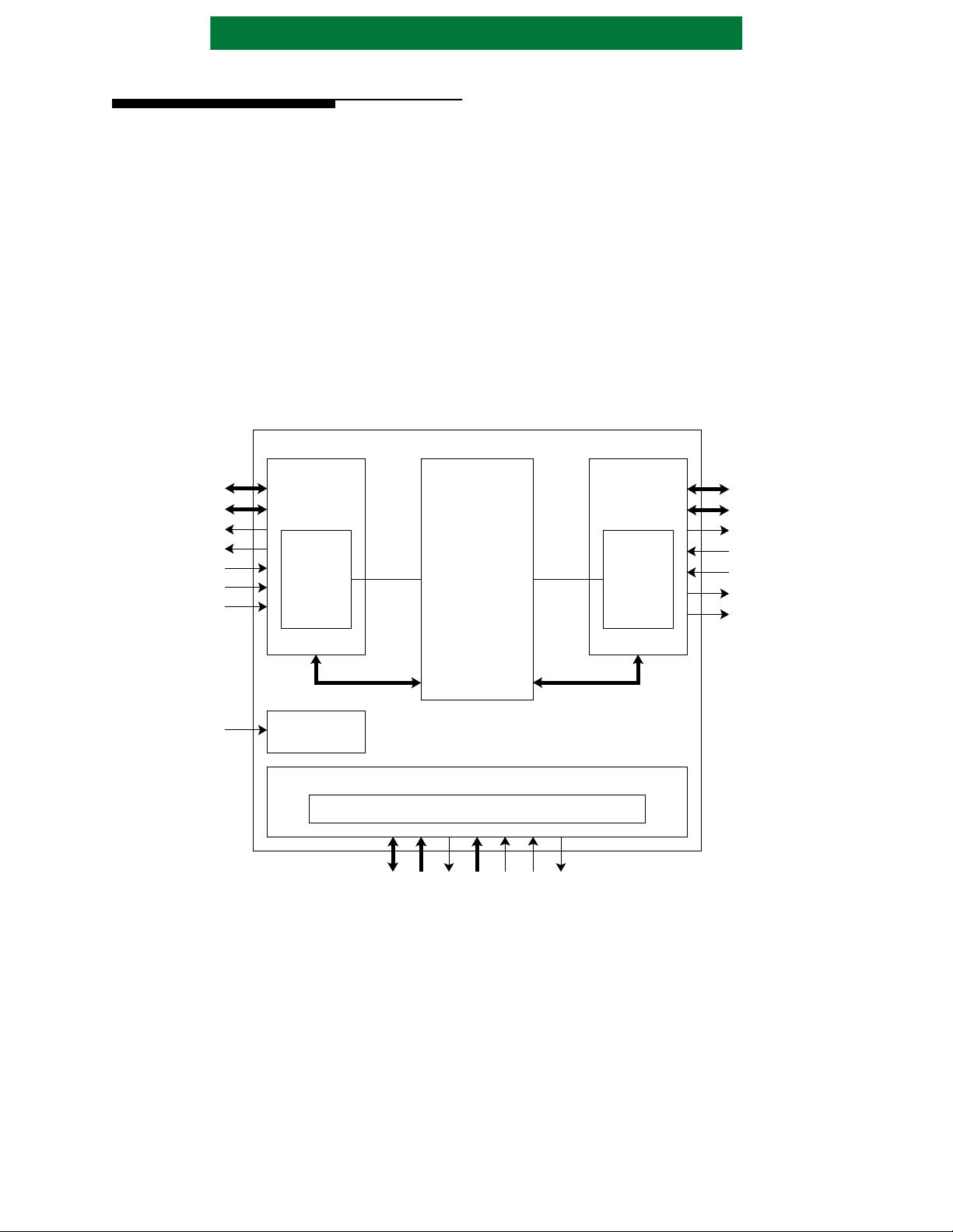
1.4 FUNCTIONAL DESCRIPTION
AHA3580 is a compression/decompression
device residing between the host interface, usually
SCSI, and the buffer manager ASIC. Major blocks
in this device are the Microproce ssor Interface, P ort
A Interface, Port B Interface, and the Compression/
Decompression Engine. The Microprocessor
Interface provides status and control information by
register access. Port A and Port B Interfaces are
configurable for polarity, handshaking modes, and
other options. The operating mode establishes the
direction of both the Port A and Port B Interfaces.
Compression or Compression P ass Through sets the
Port A Interface as an input and the Port B Interface
as an output. Conversely Decompression or
Figure 1: Functional Block Diagram
AHA3580 Compressio n Chip
ADATA[15:0]
APARITY[1:0]
ACOUT
ADBOEN
ACIN
AFF_FE
AAF_AE
PORT A
INTERFACE
PORT A
DMA
STATE
MACHINE
Decompression Pass Through sets the Port A
Interface as an output and the Port B Inter face as an
input. Decompression Output Disabled mode
allows the device to dec ompress a user programmed
number of records while dumping the
uncompressed data, then automatically begin
outputting the remaining uncompressed records.
A four byte Record Length register and a four
byte Record Count register allow the user to
partition the data into multiple records.
Compression Pass Through mode and
Decompression Pass Through modes allow data
transfers through the device without changing the
data. Both interfaces, Port A and Port B, have
selectable transfer modes.
IBM
ALDC
CORE
PORT B
INTERFACE
PORT B
DMA
STATE
MACHINE
BDATA[15:0]
BPARITY[1:0]
BCOUT
BDBOEN
BCIN
BFF_FE
BAF_AE
CLOCK
IBM is a registered trademark of IBM.
CLOCK
GENERATION
PROCESSOR INTERFACE STATE MACHINE
PROCESSOR INTERFACE
WAITN
MCIN[1:0]
MDATA[7:0]
MMODE
ADDR[4:0]
RESETN
IREQN
Page 2 of 42 PS3580-1100

Advanced Hardware Architectures, Inc.
1.4.1 PORT A AND PORT B INTERFACES
Both Port A and Port B Interfaces are
independently configurable via the Port A
Configuration registers (ACNFx), the Port A
Polarity register (APOL), th e Port B Configuration
registers (BCNFx), and the Port B Pola rity regis ter
(BPOL). Both Ports may be configured to operate in
FAS466 mode or Initiator Synchronous mode.
1.4.1.1 FAS466 DMA MODE
The FAS466 mode interface is capable of 160
MBytes/sec burst data transfers into or out of the
Port A and Port B Interfaces.
A data transfer consists of DREQx followed by
DACKx asserting. DACKx is only asserted when
the FIFO status signals, xFF_FE and xAF_AE,
permit a transfer. Slave Mode Read operation
differs from Slave Mode Write such that data
transfers are delayed one clock with Slave Mode
Read. Transf ers are also delayed one clock with Port
B F AS466 Master Mode W rite opera tion. T ransfer s
are not delayed one clock after a valid DACKx with
Port A FAS466 Slave Mode Write and Port B
FAS466 Master Mode Read transfers.
FAS466 Port A Slave Mode Read operation
transfers data from the external device to the
AHA3580 Po rt A interface. During a read
operation, ADBOEN must be asserted. A 16-bit
transfer occurs on the second clock cycle after
assertion of DACKA. Transfers continue always
delayed to the second clock after a valid DACKA.
Port B FAS466 Master Mode Write operation
functions similarly since data transfers also are
delayed to the second clock after a valid DACKB
signal.
FAS466 Port A Slave Mode Write operation
transfers data from the AHA3580 Port A interface
to the external device. ADBOEN must be
deasserted for a write transfer. When DACKA is
asserted, each rising edge of cl ock transfers a 16-bit
data word to the external device. Port B Master
Mode Read operation functio ns similarly since data
transfers occur every clock edge if DACKB is
asserted.
The AHA3580 monitors the input FIFO status
signals, AFF_FE and AAF_AE, at Port A and
controls the transfer via the DACKA signal, thus
avoiding data loss and/or FIFO corruption. When
ADBOEN is asserted during a read transfer, the
external FAS466 device drives the 16-bit data and
parity onto the ADATA[15:0] and APARITY[1:0]
for transfers into the AHA3580 device.
When AFF_FE is asserted, data can not be
transferred (DACKx will not be asserted). When
AAF_FE is asserted, data is trans ferred e very other
clock while sampling AFF_FE.
The AHA3580 Port B asserts BFF_FE when the
FIFO is empty during a write transfer or ful l during
a read transfer i ndi cating that no more data may be
transferred. Port B a sserts BAF_AE when the FIFO
is almost empty during a write trans fer or almost full
during a read transfer. When BAF_AE is asserted,
transfers should be done every other clock while
checking the status of the BFF_FE signal to
determine if another t ra nsf er ca n be done. DREQB
will remain asserted during the entire transfer.
1.4.1.2 INITIATOR SYNCHRONOUS DMA MODE
This mode is compatible with the SCSI DMA
Initiator Synchronous mode of the AIC-43C97C
device from ST Microelectronics. The SCSI
controller should be programmed for two clock
wide trans fer cycles, 16-bit interface, and
synchronous mode. The maximum transfer rate in
this mode is 40 Mega transfers per second with an
80 MHz clock, or 80 Mbytes per second.
During a decompressi on or decompression pa ss
through operation data is t ransferred from Port A to
the external SCSI controller. The AHA device
drives the data on the ADATA[15:0] and asserts
DREQA. The external device accepts the data and
responds by asserting a DACKA. Multiple DREQA
pulses along with data may occur before the first
DACKA gets asserted.
During a compression or compression pass
through operation data is transferred from the
external SCSI control ler to Port A. In this mode the
AHA device generates a DREQA pulse. The
external device responds by driving the data onto
the bus and asserting the DACKA signal. The
external device may receive multiple DREQA
pulses before responding with the first data word
and a DACKA pulse.
The AHA device will stop generating DREQA
pulses if the n umber generated is 16 greater than the
number of DACKA pulses received. The total
number of DACKA pulses must match to total
number of DREQA pulses.
Port B Initiator Synchronous DMA Mode is
similar except it opera tes as a Slave port and the DMA
count is programmed in the e xternal device. During a
decompression or decompression pass through
operation data is transferr ed from the external device
to Port B. The external devi ce dri v es the dat a on the
BDATA[15:0] and as ser ts DREQB. The AHA3580
accepts the data and responds by asserting DACKB.
Multiple DREQB pulses along with data may o ccur
before the first DACKB gets asser ted .
PS3580-1100 Page 3 of 42
Advanced Hardware Architectures, Inc.
During a compression or compression pass
through operation data is transfe rred from Port B to
the external device. In this mode the external device
generates a DREQB pulse. The AHA device
responds by driving the data onto the bus and
asserting the DACKB signal. The AHA device may
receive multiple DREQA pulses, up to a maximum
of 16, before respondi ng with the first data word a nd
a DACKB pulse.
The total number of DACKB pulses mus t match
the total num ber of DREQB pulses. The exte rnal
device may not generate a DREQB if the DREQB
count is 16 greater than the DACKB count.
1.4.2 DATA EXPANSION DURING
COMPRESSION
Data expansion occurs when the size of the data
increases during a compression operation. This
typically occurs when the data is compress ed prior
to input into the chi p.The EXPAND status bit is set
if the Port B Transfer Count is larger than the Port
A T ransfer Cou nt reg ister. If data expansion caused
the Port B T rans fer Count to exceed its maximum 4-
byte value then the BTC Overflow Error status gets
set. Worst case expansion allowable by the
algorithm is 12.5% or (9/8 ti mes the uncomp ressed
Record Length).
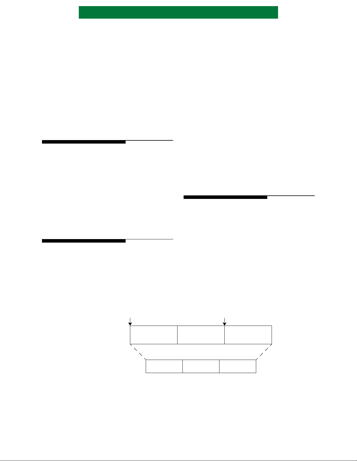
1.4.3 MULTIPLE RECORDS
The AHA3580 device has two provisions to
manage compressing a block of data into multiple
records: automatic segmentation into multiple
records at the Port A interface and the Reset history
buffer command. During compression operation,
the Port A interface autom atically partitions the
uncompressed data into equal length records
according to the Record Count and Record Length
registers. The two sets of registers determine the
number of records and length of each record in the
data transfer operati on. When compressing multiple
records the devi ce retains the con tents of the hist ory
buffer between records. This usually improves
compression ratio by al lowing data from the current
record to match against data from the previous
record. During decompress ion, t he previ ous re cord
must be decompressed prior to the current record
unless the history buffer is reset just before
compressing the curr ent record. For example, Figure
2 shows three records with a history buffer reset
before record three. In this case, record three can be
decompressed without previously decompressing
records one and two. However, decompressing
record two requires deco mpressing rec ord one fi rst.
When process ing multiple rec ords (Record
Count is greater tha n on e), the Rec ord Length must
be greater than 0x22.
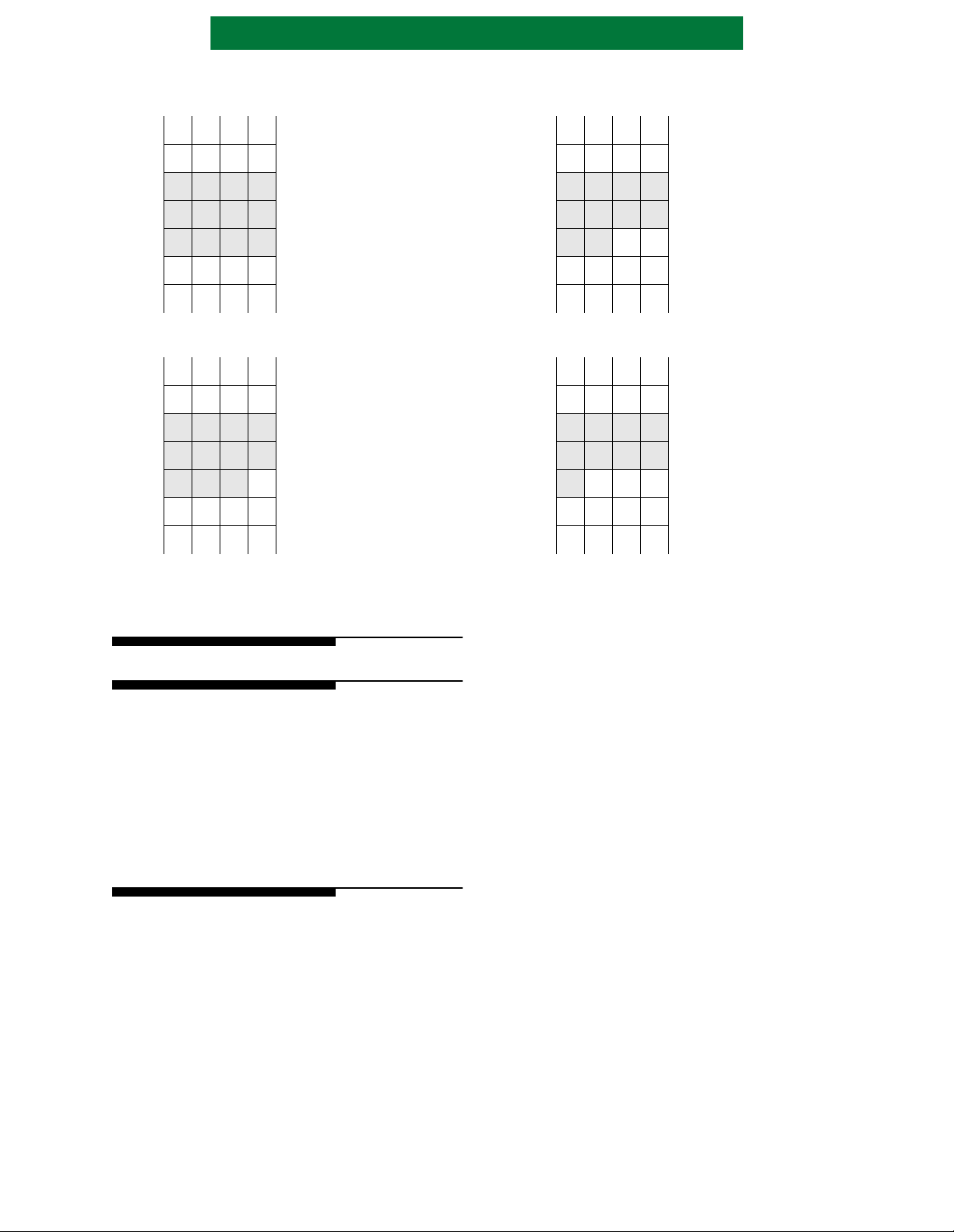
1.4.4 BYTE ALIGNMENT
Both the Port A and Po rt B interfaces support the
insertion and re moval of padding byte s to align data
transfers to any byte bounda ry wit hin a t wo-byte or
four-byte wide memory system. Figure 3 shows the
four padding possibilities. In this figure, padding
bytes are designated P
designated D
. Four bits w i thin the command
i
register are used to specify the desired input and
output padding for a given command.
Pad bytes are no t counted by any of the counters.
, and normal data bytes are
i
Figure 2: Multiple Record Compression
History
Buffer Reset
Port A
Uncompressed
Data
Port B
Compressed
Data
Page 4 of 42 PS3580-1100
RECORD 1
Compressed
RECORD 1
History Buffer Reset
(optional)
RECORD 2 RECORD 3
Compressed
RECORD 2
Compressed
RECORD 3
Advanced Hardware Architectures, Inc.
Figure 3: Port A Interface Input Padding
D11D10D9D
n+8
D7D6D5D
n+4
D3D2D1D
n
D10D9D8D
n+8
D6D5D4D
n+4
D2D1D
n
Port A Data Transfers
ADATA
8
4
0
Part (a): Zero Bytes of Padding
[15:8] [7:0]
D
1
D
3
D
5
D
7
Port A Data Transfers
ADATA
7
3
0
Part (b): One Byte of Padding
[15:8] [7:0]
D
0
D
2
D
4
D
6
Port A Data Transfers
ADATA
D9D8D7D
n+8
D
0
D
2
D
4
D
6
D5D4D3D
n+4
D1D
n
0
6
2
Part (c): Two Bytes of Padding
[15:8] [7:0]
P
1
D
1
D
3
D
5
P
D
D
D
0
0
2
4
Port A Data Transfers
ADATA
D8D7D6D
n+8
P
0
D
1
D
3
D
5
D4D3D2D
n+4
D
n
0
5
1
Part (d): Three Bytes of Padding
[15:8] [7:0]
P
1
D
0
D
2
D
4
P
P
D
D
0
2
1
3
2.0 COMPRESSION OPERA TION
2.1 COMPRESSION PASS THROUGH
Compression Pass Through mode allows data to
enter the Port A Interface, transfer through the ALDC
core and exit through the Port B Interface unchanged.
Pass through mode uses the P ort A Transfer counter ,
Port B T ransfer count er and Record Length and
Record Count re gi st e rs . T he DONE status bit an d
interrupt (if not masked) are set when the transfer
completes.
2.2 COMPRESSION
During compression operation, uncompressed
data flows into the Port A Interface, is compressed
by the compression engine , and the compressed data
transferred out of the Port B Interface.
The device contains a Content Addressable
Memory (CAM). The CAM is the history buffer
during compression operation. The compressor
appends an end marker control code to the end of the
compressed data. I t also pads the end of a transfer to
a byte boundary with zeroes.
The compression engine constantly monitors the
performance of compression for expansion during
compression operation. When the Port B Transfer
Count is la r ger th an t he Port A Transfer Count the
EXP AND bit in the Status 0 register is set indicating
data expansion during compression operation.
Port A Interface count increments with each
byte received and when this count equals the
transfer size, all bytes in this transfer have been
received into Port A.
A compression oper ation is comple te whe n t he
last byte transfer s out of the Port B Int erface and the
Record Lengt h is zero and the Recor d Count is one,
thus setting the DONE status bit and generating a
Done Interrupt if it is not masked.
PS3580-1100 Page 5 of 42
Advanced Hardware Architectures, Inc.
3.0 DECOMPRESSION OPERATION
3.1 DECOM PRESSION P ASS THR OUGH
Decompression Pass Through mode allows data
to enter the Port B Interface, transfer through the
ALDC core and exit through the Port A Interface
unchanged. Pass through mode uses the Port A
Transfer counter, Port B Transfer counter, Record
Length and Record Count registers. The DONE
status bit and interrupt (i f not masked) are set when
the transfer completes.
3.2 DECOMPRESSION
During Decompression mode, compressed data
flows into the Port B Interface and is decompress ed.
The resulting uncompressed data is transfer red out of
the Port A Interface.
A decompression operation is complete when
the last byt e transfers out of the Port A In terface,
thus setting the DONE status bit and generating a
Done Interrupt if it is not masked.
Decoder Control Code Errors are generated if
invalid control codes are detected in the compressed
data stream. This error is reported in the Error
Status register.
Multiple records can be decompressed by
programming the Record Count register. The
Record Count register decrements every time an
End of Record is decoded.
3.3 DECOMPRESSION OUTPUT DISABLED MODE
Decompression output disabled mode allows
the user to program the number of records into the
Data Disable Count register to decompress while
discarding the output. The device then switches to
normal decompression mode and continues to
decompress the remaining records determined by
the remainin g number of records in the Record
Count register , a nd trans fers this data out of Por t A.
4.0 MICROPROCESSOR INTER-
FACE AND REGISTER ACCESS
4.1 MICROPROCESSOR INTERFACE
Microprocessor Interface configuration is
determined by the MMODE pin. If MMODE is tied
high, transfers are cont rolled by a ch ip select sign al
(CSN) and a read/wri te signal (RWN), if MMODE
is tied low, transfers are controlled by separate read
(READN) and write (WRITEN) signals. Refer to
Section 10.0 Timing Specifications for timing
diagrams.
Table 1: Microprocessor Interface Cont r o l Sig nals
PIN NAME MMODE TIED LOW MMODE TIED HIGH
MCIN[0] READN CSN
MCIN[1] WRITEN RWN
WAITN WAITN WAITN
ADDR[0]
ADDR[0] = 0 selects register bits 7:0
ADDR[0] = 1 selects register bits 15:8
4.1.1 INTERRUPTS
IREQN is th e hardware interrupt signal.
IREQN is a standard TTL output. When active, it
indicates an interrupt is set in the device. The
microprocessor can determine the cause of the
interrupt by reading the Interrupt Status register.
Masking individual interrupts with the
Interrupt M ask register disables particular
interrupts from causing the interrupt signal pin to
assert (IREQN).
state when either a hardware or software reset
occurs, new compression operation begins, or by
writing a zero to the Interrupt Status bit.
get set even if the Interrupt Mask bits are set. The
exceptions are the One Byte at Port B, End of
Record at Port B, One Byte at Port A, and End of
Record at Port A. If these interrupt s are masked, this
status informat ion can only be provided at the end of
transfer, not at end of records because the ALDC
core does not identify end of records in the data
stream.
ADDR[0] = 0 selects register bits 15:8
ADDR[0] = 1 selects register bits 7:0
The interrupt signals are reset to their inactive
In general, t he Interrupt Status and Status bits
Page 6 of 42 PS3580-1100

Advanced Hardware Architectures, Inc.
4.1.2 RESETS
There is a hardware reset signal and a software
reset. When the RESETN signal is asserted all
registers are reset, current oper ations a re cance lled,
and the history buf fer is cleared . The s oftware reset
via the Command register does not affect the
Configuration registers (ACNF or BCNF),
Identification register (ID), the Polarity registers
(APOL or BPOL), or the Command register
(CMND). Al l other registers are reset, cu rrent
operations cancelled and the history buffer cleared.
Section 6.0 Register Description lists the
register values after a hardware reset, software reset
command, and after a transfer command.
A new transfer command doe s not reset the data
path; therefor e, a hardware re set or softwar e reset is
generally required prior to issuing a new transfer
command.
4.1.3 PORT A INTERFACE FIFO ACCESS
It is possible to access the Port A Interface FIFO
from the microprocessor interface. This allows the
uncompressed data strea m to be altered from the
microprocessor. This may be useful to properly
handle exception conditions. Both read and write
accesses are available. Only the Port A Interface
FIFO is accessible from the microprocessor
interface. In order to access the FIFO from the
microprocessor int erface, dat a transfers on the Port
A interface must be suspended. The DMA device
attached to the Port A interface must deactivate the
DREQA line before attempting to access t he FIFO
from the microprocessor interface. Unpredictable
results occ ur if DREQA is active during FIFO
access from the microprocessor interface.
Two registers are used to control access to the
FIFO: the Port A FIFO Contr ol (AFCT) register and
the Port A FIFO Data (AFIF) register. AFIF is a
two-byte register used to hold data to be written to
the Port A Interface FIFO during compression
operations and to hold data read from the Port A
Interface FIFO during decompression operations.
Two bits within AFCT are defined: Access Port A
FIFO (ACCF) and Request Port A FIFO (REQF).
The Access Port A FIFO bit must be set for the
entire duration of a read or write access to the Port A
FIFO. This bit controls whether the Port A FIFO is
accessed from the Port A interface or the
microprocessor int erface. The REQF bit is used as a
semaphore to reques t a read or a writ e to the P ort A
Interface FIFO. Read or write is determined by the
current command being executed. The FIF O can be
read only during deco mpression commands and ca n
be written only during compression commands.
Writing to the Port A Interface FIFO, assuming
a compression or compression bypass operation is
being executed, requires the following:
1) Suspend transfers on Port A Interface
(DREQA input must be deasserted).
2) Write a Select Port A Command.
3) Set ACCF.
4) Place data to be written to the original data
interface FIFO in AFIF.
5) Set REQF.
6) Read REQF until REQF returns to a zero.
7) Repeat steps 3 to 5 as necessary.
8) Clear ACCF and resume DMA operations.
Reading from the Port A Interface FIFO,
assuming a decompression bypass, decompression
or decompression output disabled operation is being
executed, requires the following:
1) Suspend transfers on Port A Interface
(DREQA input must be deasserted).
2) Write a Select Port A Command.
3) Set ACCF.
4) Set REQF.
5) Read REQF until REQF returns zero.
REQF is reset when two bytes have been read
from the Port A Interface FIFO and placed in
AFIF.
6) Read data from AFIF.
7) Repeat steps 3 to 5 as necessary.
8) Clear ACCF and resume DMA operations.
All Port A interface status indicators are
updated exactly as if the data is read from or written
to the Port A interface data bus. For instance:
• The Port A Interface Transfer Count (ATC)
will increment as b ytes are transferred through
the microprocessor interface.
• All Status bits (STAT0 and STAT1) and
Interrupt Status bits (INTS) will operate when
data is transferred through the microprocessor
interface.
• Padding bytes are supported at command
boundaries.
• Padding bytes may have to be inserted to
ensure that the last transfer from the
microprocessor ends on an even-byte
boundary.
PS3580-1100 Page 7 of 42
Advanced Hardware Architectures, Inc.
4.2 REGISTER ACCESS
MMODE determines whe ther ADDR[0] selects
even or odd addressed registers. When MMODE = 1
and ADDR[0]=0, odd addressed registers are
accessible. MMODE=1 causes ADDR[0] input
signal to be inverte d.
The registers may not be stable if PAUSED is
not set. Registers should onl y be written when they
are stable.
When writing to registers that are defined as 16-bit
registers, both bytes must be written before the register
is updated. When writing the 16-bit Command
register, the command is executed when the most
significant byte is written. ADDR[0] selects between
the upper and lower bytes of 16-bit registers.
Registers in the ALDC core require long er to
access than the external microprocessor interface
permits. Therefore, if back to back writes to the
same address ever occur, they must be separated by
a minimum of 8 clocks.
4.3 PAUSING / RESUME
(DACKx) deasserts. When a port is in master mode,
the PAUSED status bit will get set even if xCO UT
(DREQx) is asserted. However, in this case, several
transfers could occur before the interface pauses
and DREQx remains deassert ed. Status updat es and
no more transfers will occur. Once paused and the
last transfer is complete, the data busses are put in
high impedance. Operat ion is continued by issuing a
resume command
Registers in the ALDC core req uir e lo nger to
access than the externa l mic ropr oces sor int erf ace
permits. Therefore, th ese registers must be prefetched
for external reads . T o assure that the val ues read from
these registers are curr ent , it is recommended that a
Pause command be issued and Pau sed Status read
prior to reading these reg ist ers . When a pause
command is received, it takes up to 40 clock cycles to
update these regist ers. The PAUSED status bit is not
set until the registers are updated. Additional
microprocessor accesses dur ing t his time will delay
the prefetched reads and paused stat us. Registers that
must be prefetched includ e th e Compressed Bytes
Processed, Error Status, Interrupt Status, Record
Count and Data Disable Count regi ste rs.
When a Pause command is issued or an
unmasked data transfer interrupt occurs, the device
pauses at the next break in the DMA handshaking.
The following unmasked int errupts cause the device
to pause: ODT (Output Disable Terminated),
EORPA (End of Record at Port A), BP A ( One Byte
at Port A), EORPB (End of Recor d at Port B), BPB
(One Byte at Port B), BCMP (Port B Interface
Compare), and EORD (End of Record at Decoder).
When a port is in sl ave mode, it pauses after xCOUT
Table 2: Port A Interface Signals
SIGNAL
NAME
ACIN DACKA DREQA 7 I
ACOUT DREQA DACKA 5 O
ADBOEN deasserted ADBOEN 3 O
AFF_FE not used AFF_FE 1 I
AAF_AE not used AAF_AE 0 I
AIC-43C97C FAS466
Table 3: Port B Interface Signals
SIGNAL
NAME
BCIN DACKB DREQB 7 I
BCOUT DREQB DACKB 5 O
BDBOEN BDBOEN deasserted 3 I
BFF_FE BFF_FE not used 1 O
BAF_AE BAF_AE not used 0 O
FAS466 AIC-43C97C
5.0 PORT A AND PORT B CONFIGURATION
Port A and Port B are both 16-bit bidirectional
data ports with pa rity checki ng and gener ation. The
ports are controlled by the configuration registers
ACNF[15:0] and BCNF[15:0], and polarity
registers APOL[7:0] and BPOL[7:0].
APOL
bit
BPOL
bit
DIRECTION
DIRECTION
Page 8 of 42 PS3580-1100

Advanced Hardware Architectures, Inc.
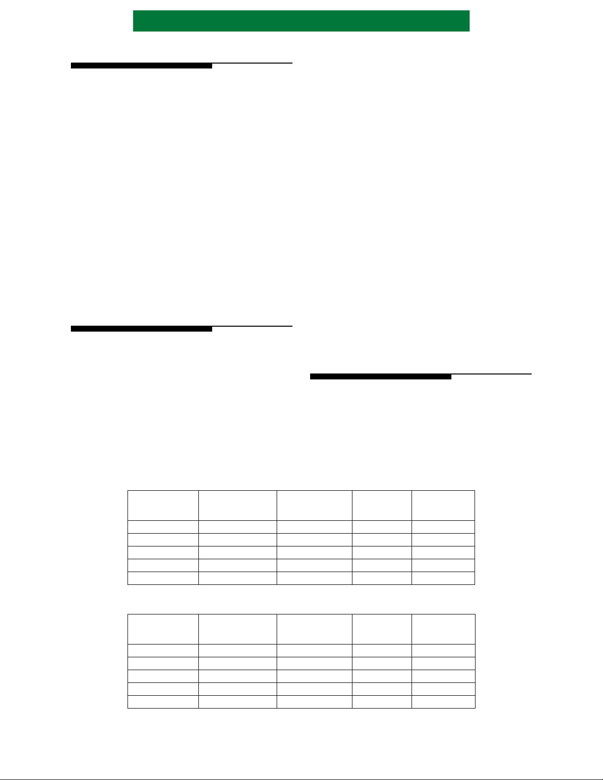
6.0 REGISTER DESCRIPTION
ADDR[4:0]
N
REGISTER RESET VALUE P
O
MMODE
0x0A 0x0B BTCL0 Port B Transfer Count, Byte 0 R 1 0x00 0x00 0x00 16
0x0B 0x0A BTCL1 Port B Transfer Count, Byte 1 R 1 0x00 0x00 0x00 16
0x0A 0x0B AFCT Port A FIFO C o n t rol R/W 2 0x00 0x00 0x00 17
0x0B 0x0A res Reserved 2
0x0A 0x0B CBPL0
0x0B 0x0A
0x0C 0x0D ERRS Error Stat u s R 1 0x00 0x00 0x00 18
0x0D 0x0C res Reserved
0x0E 0x0F INTS0 Interrupt Status, Byte 0 R/W 1 0x00 0x00 0x00 18
MMODE
= 0
0x00 0x01 STAT0 Stat u s , B y te 0 R 1 0x00 0x00 0x80 10
0x01 0x00 STAT1 Status, Byte 1 R 1, 4 0x0C 0x0C 0000UU00 11
0x00 0x01 ACNF0 Por t A Config u r a t ion, Byt e 0 R/W 2 0x00 unchanged unchanged 12
0x01 0x00 ACNF1 Por t A Config u r a t ion, Byt e 1 R/W 2 0x00 unchanged unchanged 12
0x00 0x01 BCNF0 Port B C o n f igurati o n , B yte 0 R/W 3 0x00 unchanged unchanged 12
0x01 0x00 BCNF1 Port B C o n f igurati o n , B yte 1 R/W 3 0x00 unchanged unchanged 13
0x02 0x03 ID0 Identification 0 R 1 0x80 0x80 0x80 13
0x03 0x02 ID1 Identification 1 R 1 0x35 0x35 0x35 13
0x02 0x03 APOL Port A Polarity R/W 2 0xFF unchanged unchanged 13
0x03 0x02 res Reserved
0x02 0x03 BPOL Port B P o l arity R/W 3 0xDF unchanged unchanged 14
0x03 0x02 res Reserved
0x04 0x05 ATCH0 Port A Transfer Count, Byte 2 R 1 0x00 0x00 0x00 14
0x05 0x04 ATCH1 Port A Transfer Count, Byte 3 R 1 0x00 0x00 0x00 14
0x04 0x05
0x05 0x04 RCH1 Record Count, Byte 3 R/W 2 0x00 0x00 0x00 15
0x04 0x05 BCCH0 Port B Compare Count, Byte 2 R/W 3 0x00 0x00 0x00 15
0x05 0x04 BCCH1 Port B Compare Count, Byte 3 R/W 3 0x00 0x00 0x00 15
0x06 0x07 ATCL0 Port A Transfer Count, Byte 0 R 1 0x00 0x00 0x00 14
0x07 0x06 ATCL1 Port A Transfer Count, Byte 1 R 1 0x00 0x00 0x00 14
0x06 0x07
0x07 0x06 RCL1 Record Count, Byte 1 R/W 2 0x00 0x00
0x06 0x07 BCCL0 Port B Compare Count, Byte 0 R/W 3 0x00 0x00 0x00 15
0x07 0x06 BCCL1 Port B Compare Count, Byte 1 R/W 3 0x00 0x00 0x00 15
0x08 0x09 BTCH0 Port B Transfer Count, Byte 2 R 1 0x00 0x00 0x00 16
0x09 0x08 BTCH1 Port B Transfer Count, Byte 3 R 1 0x00 0x00 0x00 16
0x08 0x09
0x09 0x08 AFIF1 Po rt A F IF O D a ta A c c es s , By t e 1 R/W 2 0x00 0x00 0x00 16
0x08 0x09 CBPH0
0x09 0x08
0x0F 0x0E INTS1 Interrupt Status, Byte 1 R/W 1 0x00 0x00 0x00 19
0x10 0x11
0x11 0x10 CMND 1 C o m m a n d 1 R/W 0x00 0xA0 0x00 20
0x12 0x13
0x13 0x12 res Reserved
0x14 0x15 RLH0 Record Length, B y t e 2 R/W 0x00 0x00 unchanged 21
0x15 0x14 RLH1 Record Length, B y t e 3 R/W 0x00 0x00 unchanged 21
MNEMONIC REGISTER NAME R/W
= 1
RCH0 Record Count, Byte 2 R/W 2 0x00 0x00 0x00
RCL0 Record Count, Byte 0 R/W 2 0x00 0x00
AFIF0 Por t A F IF O D at a A cc e s s, B y te 0 R/W 2 0x00 0x00 0x00
Compressed Bytes Processed,
Byte 2
CBPH1
CBPL1
CMND0 Command 0
res Reserved
Compressed Bytes Processed,
Byte 3
Compressed Bytes Processed,
Byte 0
Compressed Bytes Processed,
Byte 1
R/W
T
HARDW ARE
E
S
R 3 0x00 0x00 0x00 17
R 3 0x00 0x00 0x00
R 3 0x00 0x00 0x00 17
R 3 0x00 0x00 0x00
RESET
0x00 0x00 0x00
RESET
COMMAND
NEW
TRANSFER
COMMAND
0x00 15
0x00
A
G
E
#
15
15
16
17
17
20
PS3580-1100 Page 9 of 42
Advanced Hardware Architectures, Inc.
ADDR[4:0]
N
REGISTER RESET VALUE P
O
MMODE
0x1A 0x1B DDCL0 Data Disabled Count, Byte 0 R/W 0x00 0x00 unchanged 22
0x1B 0x1A DDCL1 Data Disabled Count, Byte 1 R/W 0x00 0x00 unchanged 22
0x1C 0x1D EMSK Erro r M a sk R/W 0x00 0x00 unchanged 22
0x1D 0x1C res Reserved
0x1E 0x1F IMSK0 Inter r u p t M a s k 0 R/W 0x00 0x00 unchanged 23
Notes:
1) When CMND is not a Selection Command.
2) When CMND is a Select Port A Configuration Command.
3) When CMND is a Select Port B Configuration Command.
4) U identifies a bit that is unchanged.
MMODE
= 0
0x16 0x17 RLL0 Record L e n g th, Byte 0 R/W 0x00 0x00 unchanged 21
0x17 0x16 RLL1 Record L e n g th, Byte 1 R/W 0x00 0x00 unchanged 21
0x18 0x19 DDCH0 Data Disabled Count, Byte 2 R/W 0x00 0x00 unchanged 22
0x19 0x18 DDCH1 Data Disabled Count, Byte 3 R/W 0x00 0x00 unchanged 22
0x1F 0x1E IMSK1 Inte r r u p t M a s k 1 R/W 0x00 0x00 unchanged 23
MNEMONIC REGISTER NAME R/W
= 1
T
E
S
HARDW ARE
RESET
RESET
COMMAND
NEW
TRANSFER
COMMAND
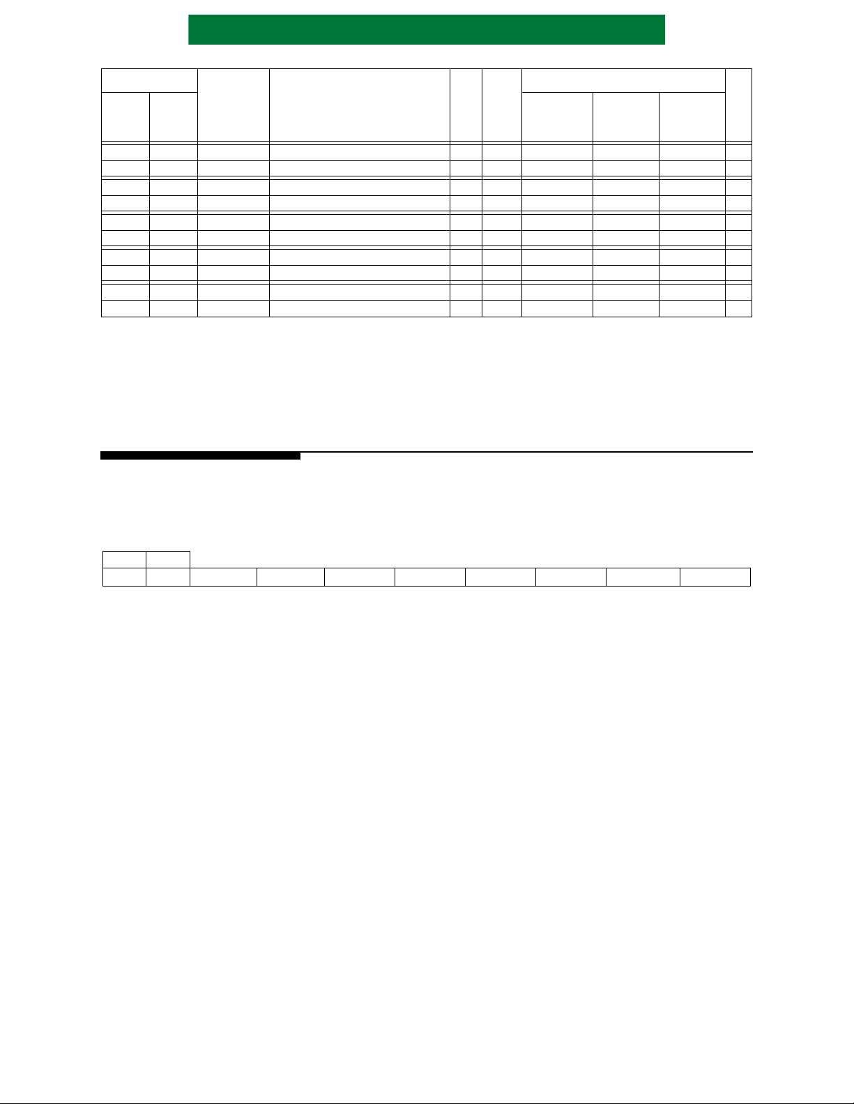
6.1 STATUS 0 (STAT0)
Read Only
Hardware Reset Value = 0x00
Reset Command = 0x00
A
G
E
#
MMODE =
01
bit7 bit6 bit5 bit4 bit3 bit2 bit1 bit0
0x00 0x01 BUSY PAUSED OUTDIS BYPASS EXP AND ANYINT ANYERR DONE
Any status bit which is active when the device pauses, due to an interrupt or Pause Command, will
remain active until there is a Resume Command.
BUSY - Busy. This bit is set when a data transfer operation begins. It is cleared when the data transfer
operation completes successfully, when an unmasked error occurs, or when a reset occurs.
PAUSED - Paused. This bit is set when a data transfer operation is currently paused. It is cleared when a
paused data transfer operation is resumed, when a reset occurs, or on a new transfer.
OUTDIS - Output Disabled. This bit i s set when Port A Interfac e output is disabled. I t is cleared when Port
A Interface output is re-enabled, when a reset occurs, or on a new transfer.
BYP ASS - Bypass. This bit is set after a Start C ompression Bypass or a Start Decompression Bypass
command is written to the Command register. It is cleared after a Start Compression, Start
Decompression, St art Decompress ion Output Disable, when a reset occurs , when an unmasked
error occurs, or when a transfer is complete.
EXP AND - Expan sion. This bit is set when the Port B Transfer Count register is larger than the Port A
Tr ansfer Count re gister . I t may toggle many times d uring a compress ion operation. It is cleared
when another data transfer operation begins or when a reset occurs.
ANYINT - Any Interrupt. This bit is set while an unmask ed in te rr upt is active. Cleared on a new transf er,
and when all unmasked interrupts have been cleared.
ANYERR - Any Error. This bit is set when an unmasked error occurs. It is cleared when a data transfer
operation begins or when a reset occurs.
DONE - Done. This bit is s et when the current data tran sfer operation is complete. It is cleared when a
data transfer operation begins or when a reset occurs.
Page 10 of 42 PS3580-1100

6.2 STATUS 1 (STAT1)
Read Only
Hardware Reset Value = 0x0C
Reset Command = 0x0C
Advanced Hardware Architectures, Inc.
MMODE =
01
0x01 0x00 EORD BCMP BPB EORPB EMPB EMPA BPA EORPA
The Status bits BPB, EORPB, BPA and EORPA will onl y get set afte r the last word i s transfe rred if the
following Interrupt Mask bits are set: BPBM, EORPBM, BPAM and EORPAM. If these bits are set, the
ALDC core provides end of transfer information, but no end of record information.
EORD - End of Record at Decoder. This bit is set when the ALDC decoder detects an End of Record
BCMP - Port B Interface Compare. Thi s bit is set when Port B T rans fer Count is gr eater than or equa l to
BPB - One Byte at Port B. During compre ssion bypass and c ompression operati ons, this bit i s set at the
EORPB - End of Record at Port B. During compression bypass and c ompression ope rations, this bit i s set
bit15 bit14 bit13 bit12 bit11 bit10 bit9 bit8
control code in the compressed data stream or when an ALDC Decoder Control Code Error
occurs. This bit is cleared af ter reset, when the de coder begins proce ssing the first code word of
the next record, or when a ne w data transfer op eration begins. I t is valid for Decompre ssion and
Decompression Output Disable modes.
Port B Interface Compare Count. Othe rwise, it is cleare d. This bit is cleared af ter reset or when
a new data transfer operation begins. This bit is valid for all modes of operation.
same time the End of Record at Port B (STAT1[4] and INTS1[4]) is set if only one byte at the
Port B Interface is part of the current record. During decompression bypass operation, this bit
is set during the las t da ta tra nsfer of the record at the Port B Interface if only on e byt e be longs
to the current r eco rd. This bit is cl ear ed aft er reset, when a new data t ran sfer operation beg ins ,
or when the first byte of the next record is transferred. Not valid during Decompression and
Decompression Output Disable modes.
when the last byte of a compressed record is transferre d out of the Port B interface. During
decompression bypass o perations, this bit is set when the last by te of a record is tr ansferred into
the Port B interface. This bit is cleared after reset, w hen a new data transfer operation begins,
or when the first byte of the next record is transferred. Not valid during Decompression and
Decompression Output Disable modes.
EMPB - Empty at Port B. This bit is set when there is no data in the Port B interface data path. This bit
must be set when writing to the Recor d Lengt h register during Dec ompression bypass operat ion
and when writing to the Record Count register during Decompression and Decompression
Output disabled operations. Set after reset.
EMP A - Empty at Port A. This bit is set when there is no data in the Port A interface data path. This bit
must be set when writing to t he Reco rd Length or Record Count registers during Compression
and Compression Bypass operations. Set after reset.
BP A - One Byte at Port A. During compression bypass and compression operations, this bit is set during
the last data transfer of the record at the Port A interface if only one byte belongs to the current
record. During decompression bypass, decompression, and decompression output disabled
modes, this bit is set the same time the End of Record at Port A interface bit (STAT1[0] and
INTS1[0]) is set if only one byte at the Port A interface is part of the current record. This bit is
cleared after reset, when a new data transfer operation begins, or when the first byte of the next
record is transferred.
EORP A - End of Record at Por t A. During compression by pass and compression operations, th is bit is set
each time the Record Length (RL) is decremented to zero. During decompression bypass,
decompression, and decompre ssion out put disabled oper ations, this bit is set whe n the last byt e
of a record is tr ansferred out the P ort A interf ace. This bit is cle ared after res et, when a new dat a
transfer op eration begins, or when the fi rst byte of the next record is tr ansferred.
PS3580-1100 Page 11 of 42

Advanced Hardware Architectures, Inc.
6.3 PORT A CONFIGURATION 0 (ACNF0)
Read/Write
Hardware Reset Value = 0x00
Reset Command = unchanged
MMODE =
01
0x00 0x01 reserved
bit7 bit6 bit5 bit4 bit3 bit2 bit1 bit0
6.4 PORT A CONFIGURATION 1 (ACNF1)
Read/Write
Hardware Reset Value = 0x00
Reset Command = unchanged
MMODE =
01
0x01 0x00 PARITY ODD SLAVE MODE[2:0] reserved
PARITY - Parity. When set, parity checking is enabled for the ADATA[15:0] data bus. When cleared,
ODD - Odd. Setting this bit along with PARITY enables odd parity checking and generation on the
SLAVE - Slave. Must always be written with a one.
MODE[2:0]-DMA Mode. These bits conf igure the in terface DMA mode of the Por t A Interfac e with values
bit15 bit14 bit13 bit12 bit11 bit10 bit9 bit8
parity checking is disabled for the ADATA[15:0] bus.
ADA TA[15:0] data bus. When cleared wi th PARITY set even parity checking and gener ation is
enabled on the ADATA[15:0] data bus.
as defined below.
MODE[2:0] DMA TYPE MASTER/SLAVE
000 Reserved —
001 Reserved —
010 Reserved —
011 Reserved —
100 Reserved —
101 FAS466 SLAVE
110 43C97C SCSI Initia tor MASTER
111 reserved —
6.5 PORT B CONFIGURATION 0 (BCNF0)
Read/Write
Hardware Reset Value = 0x00
Reset Command = unchanged
MMODE =
01
0x00 0x01 reserved FIFOTH[3:0]
FIFOTH[3:0]-FIFO Threshold. These bits configure the Port A FIFO threshold value. V alues from 0001 through
bit7 bit6 bit5 bit4 bit3 bit2 bit1 bit0
1111 are valid. A value of 0000 results in the same operation as 0001. Valid for FAS466 mode.
Page 12 of 42 PS3580-1100

Advanced Hardware Architectures, Inc.
6.6 PORT B CONFIGURATION 1 (BCNF1)
Read/Write
Hardware Reset Value = 0x00
Reset Command = unchanged
MMODE =
01
0x01 0x00 PARITY ODD reserved MODE[2:0] reserved
PARITY - Parity. When set, parity checking is enabled for the BDATA[15:0] data bus. When cleared,
ODD - Odd. When set, odd parity checking and generation is us ed on the BDAT A[15:0] data bu s. When
MODE[2:0]-DMA Mode. These bits conf igure the inte rface DMA mode of the Port B Interface wit h values
bit15 bit14 bit13 bit12 bit11 bit10 bit9 bit8
parity checking is disabled for the BDATA[15:0] bus.
cleared, even parity checking and generation is used on the BDATA[15:0] data bus.
as defined below.
MODE[2:0] DMA TYPE MASTER/SLAVE
000 Reserved —
001 Reserved —
010 Reserved —
011 Reserved —
100 Reserved —
101 FAS466 MASTER
110 43C97C SCSI Initia tor SLAVE
111 reserved —
6.7 IDENTIFICATION (ID0, ID1)
Read Only
Hardware Reset Value = 0x3580
Reset Command = 0x3580
MMODE =
01
0x02 0x03 ID[7:0]
0x03 0x02 ID[15:8]
ID[15:0]- The bits of this register correspond to the identific ation code of the chip. This register is
accessible when CMND is not a Selection Command.
6.8 PORT A POLARITY (APOL)
Read/Write
Hardware Reset Value = 0xFF
Reset Command = unchanged
MMODE =
01
0x02 0x03 ACIN reserved ACOUT reserved ADBOEN reserved AFF_FE AAF_AE
The bits of this register correspond to Port A Interface signals. A set bit programs the corresponding
signal to be active low. A cleared bit programs the corresponding signal to be active high. This register is
only accessible when CMND is Select Port A Configuration.
bit7 bit6 bit5 bit4 bit3 bit2 bit1 bit0
PS3580-1100 Page 13 of 42

Advanced Hardware Architectures, Inc.
6.9 PORT B POLARITY (BPOL)
Read/Write
Hardware Reset Value = 0xDF
Reset Command = unchanged
MMODE =
01
0x02 0x03 BCIN reserved BCOUT reserved BDBOEN reserved BFF_FE BAF_AE
The bits of this register correspond to Port B Interface signals. A set bit programs the corresponding
signal to be act ive low . A cleared bit prog rams the corresponding s ignal to be active hi gh.This register is only
accessible when CMND is Select Port B Configuration.
bit7 bit6 bit5 bit4 bit3 bit2 bit1 bit0
6.10 PORT A TRANSFER COUNT (ATCL0, ATCL1, ATCH0, ATCH1)
Read Only
Hardware Reset Value = 0x00000000
Reset Command = 0x00000000
Port A Tr ansfer Count Low
MMODE =
01
0x06 0x07 A TCL[7:0]
0x07 0x06 A TCL[15:8]
Port A Transfer Count High
MMODE =
01
0x04 0x05 ATCH[7:0]
0x05 0x04 ATCH[15:8]
ATC[31:0]- Port A Transfer Count. These registers provide status information on the number of bytes
transferred for a current data transfer operation. During a compression operation, ATC is
incremented as each ori ginal data byte is received by th e Port A Interface. When ATC equals the
product of the Record Count and Record Length during compression, all bytes in the
compression operation have been received by the AHA3580. During a decompression
operation, ATC is incremented as ea ch decom pres sed dat a byte is sent by the Por t A Inte rfac e.
This register is only accessible when CMND is not a Selection Command.
In the case where onl y one byte is re quired to complet e a transfer operation (i.e. , an odd number
of bytes in the transfer), the ATC is incremented by one after the byte transfers. ATC should not
be used to dete rmine the decompr ession operation is complete. I nstead, use the DONE status bit
and/or interrupt. Data blocks of Record Count times Record Length must be smaller th e (2
1) to prevent overf low of this 4 -byte T ransf er Count register. Reset on new transfer commands.
Pad bytes are not counted.
32
−
Page 14 of 42 PS3580-1100

Advanced Hardware Architectures, Inc.
6.11 RECORD COUNT (RCL0, RCL1, RCH0, RCH1)
Read/Write
Hardware Reset Value = 0x00000000
Reset Command = 0x00000000
Record Count Low
MMODE =
01
0x06 0x07 RCL[7:0]
0x07 0x06 RCL[15:8]
Record Count High
MMODE =
01
0x04 0x05 RCH[7:0 ]
0x05 0x04 RCH[15:8]
RC[31:0]- Record Count indicates the number of records to be compressed or decompressed. Record
Count must be set to 0x00 000001 d uri ng Decompr ession By pas s. If th e Re cord Cou nt must be
written to durin g a compr ession oper ation, the n the Empt y at Port A (EMPA) St atus bit must be
set. If the Record Count must be writ te n to dur i ng a decompression operati on, th en the Empty
at Port B (EMPB) Status bit must be set.
6.12 PORT B COMPARE COUNT (BCCL0, BCCL1, BCCH0, BCCH1)
Read/Write
Hardware Reset Value = 0x00000000
Reset Command = 0x00000000
Port B Compare Count Low
MMODE =
01
0x06 0x07 BCCL[7:0]
0x07 0x06 BCCL[15:8]
Port B Compare Count High
MMODE =
01
0x04 0x05 BCCH[7:0]
0x05 0x04 BCCH[15:8]
BCC[31:0] Port B compare count register is used to pause th e device after a s pecified number of bytes are
transferred at the Port B interface. Port B Compare Count is a four byte register with the two
most significant bytes contained in Port B Compare Count High (BCCH), and the two least
significant bytes contained in the Port B Compare Count Low register (BCCL).
PS3580-1100 Page 15 of 42

Advanced Hardware Architectures, Inc.
6.13 PORT B TRANSFER COUNT (BTCL0, BTCL1, BTCH0, BTCH1)
Read Only
Hardware Reset Value = 0x00000000
Reset Command = 0x00000000
Port B Tr ansfer Count Low
MMODE =
01
0x0A 0x0B BTCL[7:0]
0x0B 0x0A BTCL[15:8]
Port B Transfer Count High
MMODE =
01
0x08 0x09 BTCH[7:0]
0x09 0x08 BTCH[15:8]
BTC[31:0] -Port B Transfer Count. These registers provide status information on the number of bytes
transferred for a current data transfer operation. During a compression operation, BTC is
incremented as each compressed data byte is sent by the Port B Interface. During a
decompression operati on, BTC is incr emented as each compres sed data by te is rec eived by th e
Port B Interface. This register is only accessible when CMND is not a Selection Command.
In the special case where only one byte i s required to c omplete a trans fer operation (i .e., an odd
number of bytes in the transfer), the BTC is incremented by one after the byte transfers. BTC
should not be used to determine the decompression operation is complete. Instead, use the
DONE status bit and/or interrupt. Data blocks of Record Count times Record Length must be
smaller than (2
Reset by a new compression mode transfer command, but not by a new decompression mode
transfer. Pad bytes are not counted.
32
−1) to prevent overflow of this 4-byte transfer count register.
6.14 PORT A FIFO DATA ACCESS (AFIF0, AFIF1)
Read/Write
Hardware Reset Value = 0x0000
Reset Command = 0x0000
MMODE =
01
0x08 0x09 FA[7:0]
0x09 0x08 FA[15:8]
FA[15:0]- Port A FIFO Data regist er i s a te mporary holdi ng regist er fo r data t o be wr itte n to or read from
the Port A interfac e FIFO. During co mpressi on bypass and compress ion opera tions, t he Port A
FIFO indicates it has received the data by resetting REQF in the AFCT register. During
decompression bypass, decompression, and decompression output disabled operations, data
may be read from this regi ster after the Port A FIFO res ets REQF in the AFCT register. This
register is only accessible when CMND is a Select Port A Configuration Command. This
register is reset by a new transfer.
Page 16 of 42 PS3580-1100

Advanced Hardware Architectures, Inc.
6.15 COMPRESSED BYTES PROCESSED (CBPL0, CBPL1, CBPH0, CBPH1)
Read/Write
Hardware Reset Value = 0x00000000
Reset Command = 0x00000000
Compressed Bytes Processed Low
MMODE =
01
0x0A 0x0B CBPL[7:0]
0x0B 0x0A CBPL[15:8]
Compressed Bytes Processe d High
MMODE =
01
0x08 0x09 CBPH[7:0]
0x09 0x08 CBPH[15:8]
CBPL[31:0] -Compressed Bytes Processed counter. Counts the total number of bytes processed by the
ALDC decoder during decompr ession and deco mpression outpu t disabled ope rations. It can be
used in conjunction with the Port B Transfer Count to determine the number of compressed
bytes, if any, that reside in the Port B interface and AL DC core.
6.16 PORT A FIFO CONTROL (AFCT)
Read/Write
Hardware Reset Value = 0x00
Reset Command = 0x00
MMODE =
01
0x0A 0x0B reserved ACCF REQF
ACCF - Access FIFO. When set, access to the Port A FIFO is redirected from the Port A interface to the
REQF - Request to FIFO. During compre ssion bypa ss and compr ession ope rations , this bit is set to one
bit7 bit6 bit5 bit4 bit3 bit2 bit1 bit0
microprocessor interface. This bit is cleared after reset or a new transfer.
requesting a write to the Port A FIFO. During decompression bypass, decompression, and
decompression output dis abled ope rati ons, thi s bit i s set to on e reques ting a r ead fro m the Port
A interface FIFO. This bit is cleared when the Port A FIFO has completed the request or after
a reset. This regist er is only acces sible when CMND is a Sele ct Port A configu ration command.
Reset by a new transfer.
PS3580-1100 Page 17 of 42

Advanced Hardware Architectures, Inc.
6.17 ERROR STATUS (ERRS)
Read Only
Hardware Reset Value = 0x00
Reset Command = 0x00
MMODE =
01
0x0C 0x0D reserved APERR BPERR reserved BTCO ATCO ADCC reserved
The Err or Status register provides error status bits t o the microprocessor. These bits are set regardless of t he
error mask settings. Reset by a new compression mode transf er.
APERR - Port A Interface Parity Error. This bit is set when a parity error is detected during a transfer into
BPERR - Port B Interface Parity Error . This bit is se t when a parit y error is det ected durin g a transfer into
BTCO - Port B Transfer Count Overflow Error. This bit is set when a carry out is detected on the Port
ATCO - Port A Transfer Count Overflow Error. This bit is set when a carry out is detected on the Port
ADCC - ALDC Decoder Control Code Error. This bit is set during decompression when an invalid
bit7 bit6 bit5 bit4 bit3 bit2 bit1 bit0
ADATA[15:0] and the Port A Interface Parity bit is set. It is cleared when a new compression
mode transfer begins or when a reset occurs.
BDATA[15:0] and the Port B Interface Parity bit is set. It is cleared when a new compression
mode transfer begins or when a reset occurs.
B Tr ansfe r Count r egist er. It is cleared when a new compression mode t ransf er begi ns or whe n
a reset occu rs.
A Tr ansfe r Count r egist er. It is cleared when a new compression mode t ransf er begi ns or whe n
a reset occu rs.
control code is detected in the compressed data stream. It is cleared when a new compression
mode transfer begins or when a reset occurs.
6.18 INTERRUPT STATUS 0 (INTS0)
Read Only
Hardware Reset Value = 0x00
Reset Command = 0x00
MMODE =
01
0x0E 0x0F DONE PAUSED ODT reserved ERROR
Interrupt Status bits are reset by writing a zero. This is referred to as an interrupt reset. Writing a one has
no effect.
DONE - Done Inte rr upt . This bit is set when data transfer has com pl et ed on the Port B Interface during
PAUSED - Paused Interrupt. This bit is set by a Pause command, or an unmasked data transfer interrupt . It is
ODT - Output Disabled T er minated. This bit i s set when the end of record of the la st suppressed re cord
ERROR - Error In terrupt. This bit is set when an unmasked error occurs. It is cleared whe n a new
bit7 bit6 bit5 bit4 bit3 bit2 bit1 bit0
compression and when data transfer has completed on the Port A Interface during
decompression. It is cleared when a new compression mode transfer begins, when a reset
occurs, or by an interru pt reset.
cleared when a new compression mode tra nsfer begins, when a reset occurs, or by an int errupt reset.
is processed by the ALDC decoder. This bit is cleared after reset, after an interrupt reset is
written, or when a new compression mode transfer begins.
compression mode transfer begins or when a reset occurs. The Error Status register is used to
determine the cause of the error.
Page 18 of 42 PS3580-1100

Advanced Hardware Architectures, Inc.
6.19 INTERRUPT STATUS 1 (INTS1)
Read/Write
Hardware Reset Value = 0x00
Reset Command = 0x00
MMODE =
01
0x0F 0x0E EORD BCMP BPB EORPB reserved BPA EORPA
The Interrupt Status bits BPB, EORPB, BPA and EORP A will only get set after the last word is
transferred if the fol lowing Interrupt Mask bits are set: BPBM, EORPBM, BPAM and EORP AM. If these
mask bits are set, the ALDC core provides end of transfer information, but no end of record information.
EORD - End of Record at Decoder, This bit is set when the ALDC decoder detects an End of Record
BCMP - Port B Interface Compare. Thi s bit is set when Port B T rans fer Count is gr eater than or equa l to
BPB - One Byte at Port B. During compre ssion bypass and c ompression operati ons, this bit i s set at the
EORPB - End of Record at Port B. During compression bypass and c ompression ope rations, this bit i s set
bit15 bit14 bit13 bit12 bit11 bit10 bit9 bit8
control code in the compressed data stream or when an ALDC Decoder Control Code Error
occurs. This bit is cleared after reset, when an interrupt reset is written, or when a new
compression mode transfer begins.
Port B Interface Compare Count. This bit is cleared after reset, when an interrupt reset is written,
or when a new compression mode transfer begins.
same time the End of Record at Port B (STAT1[4] and INTS1[4]) is set if only one byte at the
Port B Interface is part of the current record. During decompression bypass operation, this bit
is set during the las t da ta tra nsfer of the record at the Port B Interface if only on e byt e be longs
to the curre nt record. This bit is cleared after reset, wh en an interrupt reset is written, or when
a new compression mode transfer begins.
when the last byte of a compressed record is transferre d out of the Port B interface. During
decompression bypass o perations, this bit is set when the last by te of a record is tr ansferred into
the Port B interface. Thi s bit i s clea red aft er re set, when a n in terru pt res et is wr itte n, or when a
new compression mode transfer begins.
BP A - One Byte at Port A. During compression bypass and compression operations, this bit is set
during the last dat a trans fer of the reco rd at th e Port A int erfa ce if only one byte bel ongs to the
current record. During decompression bypass, decompression, and decompression output
disabled modes, this bit is set the same time the End of Record at Port A interface bit (STAT1[0]
and INTS1[0]) is set if only one byte at the Port A interface is part of the current record. This
bit is cleare d after reset, w hen an interrup t reset is written, or when a new compressio n mode
transfer begins.
EORP A - End of Record at Port A. During compression bypass and compre ssion operation s, this bit is set
each time the Record Length (RL) is decremented to zero. During decompression bypass,
decompression, and decompre ssion out put disabled oper ations, this bit is set whe n the last byt e
of a record is transferred out the Port A interface. This bit is cleared after reset, when an interrupt
reset is written, or when a new compression mode tr ansfer begin s.
PS3580-1100 Page 19 of 42

Advanced Hardware Architectures, Inc.
6.20 COMMAND (CMND)
Read/Write
Hardware Reset Value = 0x0000
Reset Command = 0xA000
MMODE =
01
0x10 0x11 CMND[7:0]
0x11 0x10 CMND[15:8]
Unspecified opcodes are reserved and may not be writt en.
CMND[15:0]-Command.This register provides for operation as described in the following table.
CMND[15:0] ACTION
SELECTION COMMANDS
0xC100
0xC200
0x5000-0x500F
0x5800-0x580F
0x6000-0x600F
0x6800-0x680F
0x6C00-0x6C0F
Select Port A Configuration. The Port A Configuration and Port A
Polarity registers are enabled for reads and writes.
Select Port B Configuration. The Port B Configuration and Port B
Polarity registers are enabled for reads and writes.
TRANSFER COMMANDS
(Described in Sections 2.0 and 3.0)
Start Compression Bypass.
– CMND[3:2] determines the numb er of pad byt es t o expec t at the Po rt A
interface.
– CMND[1:0] determines the numbe r of pad bytes to insert at the Port B
interface.
Start Compression.
– CMND[3:2] determines the numb er of pad byt es t o expec t at the Po rt A
interface.
– CMND[1:0] determines the numbe r of pad bytes to insert at the Port B
interface.
Start Decompression Bypass.
– CMND[3:2] determines the number of pa d bytes to ex pec t at th e Port B
interface.
– CMND[1:0] determines the numbe r of pad bytes to insert at the Port A
interface.
Start Decompression.
– CMND[3:2] determines the number of pa d bytes to ex pec t at th e Port B
interface.
– CMND[1:0] determines the numbe r of pad bytes to insert at the Port A
interface.
Start Decompression Output Disabled.
– CMND[3:2] determines the number of pa d bytes to ex pec t at th e Port B
interface.
– CMND[1:0] determines the numbe r of pad bytes to insert at the Port A
interface.
Page 20 of 42 PS3580-1100

Advanced Hardware Architectures, Inc.
CMND[15:0] ACTION
CONTROL COMMANDS
Pause. When a data tra nsfer operat ion is in pro gress, any curr ent operati on
steps are co mpleted and the Port A Interface and Port B Interface data
0x4200
0x4400-0x440F
0xA000
0xA400 Reset the history buffer. Only use between compression operations.
0x0000 NOP, no operation is performed.
busses are placed into a high impedance state. The Paused Interrupt and
Paused Status bits are then set. All data currently being processed by the
data transfer operation is preserved.
Resume. A previously paused data t ransf er ope rati on resumes p roces sin g.
The Paused Interr upt and Paused sta tus bits are cl eared and the Busy status
bit is set.
– RESUME[3:2] determines the number of pad bytes at the Port B
interface.
– RESUME[1:0] determines the number of pad bytes at the Port A
interface.
Software Reset. The Port A Configuration, Port B Configuration,
Identification, Port A Polarity, and Port B Polarity registers are not
affected b y t his command. All oth er reg isters are reset, current operat ion s
are cancelled, and the hist ory buf fer is clear ed. Twelve clocks are require d
to complete the reset operation. Suspend writing to any registers during
this time.
MISCELLANEOUS COMMANDS
6.21 RECORD LENGTH (RLL0, RLL1, RLH0, RLH1)
Read/Write
Hardware Reset Value = 0x00000000
Reset Command = 0x00000000
Record Length Low
MMODE =
01
0x16 0x17 RLL[7:0]
0x17 0x16 RLL[15:8]
Record Length High
MMODE =
01
0x14 0x15 RLH[7:0]
0x15 0x14 RLH[15:8]
RL[31:0]- The Record Length r egister indicates the number of Bytes cont ained in each uncompr essed data
record for compres sion bypass and c ompression opera tions. This regi ster decrement s with each
Byte transferred into Port A. When the Record Length reaches zero, the Port Interface bits
STAT 1[ 8] a nd I NTS1[8] are set. During d eco mp res si on by pas s operations, the Record Length
register indicates the total number of bytes to transfer. Record Length is not used for
decompression and decompression output disabled operations.
When processing m ultiple records (Record Co unt is g reater than one) , the Reco rd Leng th must
be greater th an 0x22. If Record Length = 0x 00000000 when a ne w transfer or r esume command
are written, the counter rolls over to 0x10000000. When Record Count is greater than 1, then
Record Length must be greater than 0x22. Pad bytes are not counted.
PS3580-1100 Page 21 of 42

Advanced Hardware Architectures, Inc.
6.22 DATA DISABLED COUNT (DDCL0, DDCL1, DDCH0, DDCH1)
Read/Write
Hardware Reset Value = 0x00000000
Reset Command = 0x00000000
Data Disabled Count Low
MMODE =
01
0x1A 0x1B DDCL[7:0]
0x1B 0x1A DDCL[15:8]
Data Disabled Count High
MMODE =
01
0x18 0x19 DDCH[7:0]
0x19 0x18 DDCH[15:8]
DDC[31:0]- Data Disabled Count.The Data Disabled Count register provides the microprocessor control of
the number of records skip ped during a S tart Decompr ession Outpu t Disabled opera tion. If the
Data Disabled Count is s et to z ero dur in g a S tar t Decompre ssion Outp ut Disa bled ope rati on or
the DDC is greater than the Record Count during a Start Decompression Output Disabled
operation, then the Port A Interface output is disabled for the entire transfer.
6.23 ERROR MASK (EMSK)
Read/Write
Hardware Reset Value = 0x00
Reset Command = 0x00
MMODE =
01
0x1C 0x1D reserved APERRM BPERRM reserved BTCOM ATCOM ADCCM reserved
The Error Mask register provides error reporting configuration to the micro processor. If an unmasked error
status bit is active, ANYERR status and ERROR interrupts are set. Errors are masked by setting the appropri ate
mask bit to one.
APERRM -Port A Interface Parity Error Mask.
BPERRM -Port B Interface Parity Error Mask.
BTCOM - Port B Transfer Count Overflow Error Mask.
ATCOM - Port A Transfer Count Overflow Error Mask.
ADCCM - ALDC Decoder Control Code Error Mask.
bit7 bit6 bit5 bit4 bit3 bit2 bit1 bit0
Page 22 of 42 PS3580-1100

Advanced Hardware Architectures, Inc.
6.24 INTERRUPT MASK 0 (IMSK0)
Read/Write
Hardware Reset Value = 0x00
Reset Command = 0x00
MMODE =
01
0x1E 0x1F DONEM PAUSEDM ODTM reserved ERRORM
The Interrupt Mask 0 register masks the individual interrupts all owing the user t o control which one s may
cause the Interrupt signal pin (IREQN) to asse rt. For e xample, if DONEM and PAUSEDM are set with
ERRORM cleared, only an ERROR interrupt will cause the Interrupt signal pin t o assert. I nterrupts are masked
by setting the appropriate mask bit t o one.
DONEM - Done Interrupt Mask.
PAUSEDM -Paused Interrupt Mask.
ODTM - Output Disabled Terminated Mask.
ERRORM -Error Interrupt Mask.
bit7 bit6 bit5 bit4 bit3 bit2 bit1 bit0
6.25 INTERRUPT MASK 1 (IMSK1)
Read/Write
Hardware Reset Value = 0x00
Reset Command = 0x00
MMODE =
01
0x1F 0x1E EORDM BCMPM BPBM EORPBM reserved BPAM EORPAM
bit15 bit14 bit13 bit12 bit11 bit10 bit9 bit8
The Interrupt Mask 1 register masks the individual interrupts allowing the user to control which ones
may cause the Interrup t signal pin ( IREQN) to assert. I nterrupts a re masked by set ting the appropr iate mask
bit to one.
EORDM - End of Record at Decoder Interrupt Mask.
BCMPM - Port B Interf ace Compare Interrupt Mask.
BPBM - One Byte at Port B Interrupt Mask.
EORPBM -End of Record at Port B Interrupt Mask.
BP AM - One Byt e at Port A Interru pt Mask.
EORP AM -End of Record at Port A Interrupt Mask.
PS3580-1100 Page 23 of 42

Advanced Hardware Architectures, Inc.
7.0 SIGNAL DESCRIPTIONS
This section contains descriptions for all the pins. Each signal has a type code associated with it. The
type codes are described in the following table.
TYPE CODE DESCRIPTION
I Input only pin
O Output only pin
I/O Input/Output pin
7.1 MICROPROCESSOR INTERFACE
MICROPROCESSOR INTERFACE
SIGNAL TYPE DESCRIPTION
MDATA[7:0] I/O Microprocessor data bus Hi-Z
MCIN[0] I
MCIN[1] I
WAITN O
ADDR[4:0] I
MMODE I Microprocessor Interface mode selector pin. Input
RESETN I Hardware reset signal. Input
IREQN O Interrupt request output signal. High
CLOCK I Clock input Input
+TIE I These pins must be tied high in the system. Input
−TIE I These pins must be tied low in the system. Input
Microprocessor interface control pin [0]. If MMODE is high
this pin is CSN. If MMODE is low this pin is READN.
Microprocessor interface control pin [1]. If MMODE is high
this pin is RWN. If MMODE is low this pin is WRITEN.
Microprocessor output signal. WAITN is driven during CSN
and then goes to tristate with a resistive pullup.
Microprocessor Interface address bus, used to select internal
registers.
DEFAULT
AFTER RESET
Input
Input
High
Input
Page 24 of 42 PS3580-1100

Advanced Hardware Architectures, Inc.
7.2 PORT A INTERFACE
PORT A INTERFACE
SIGNAL TYPE DESCRIPTION
ACIN I
ACOUT O
ADBOEN O
APARITY[1:0] I/O
ADATA[15:0] I/O
AFF_FE I
AAF_AE I
Port A Interface Control Input signal. This signal functions as
DREQA. Polarity is programmed by APOL[7].
Port A Interface Control Outp ut signa l. This s ignal f uncti ons a s
DACKA. Polarity is programmed by APOL[5].
Port A Interface Control signal. Controls direction of Port A
transfers. A low leve l indi cate s tran sfers into P ort A, and a h igh
level indicates transfers out of Port A.
When enabled, this pin checks parity on input and generates
parity for output for the AD bus. APARITY[0] is used for
AD[7:0], and APARITY[1] is used for AD[15:8]. Setting
ACNF[15]=1 enables APARITY[0]. Setting ACNF[15]=1 and
ACNF[10]=1 enables APARITY[1]. When disabled these pins
may be tied high, tied low or not connected.
Port A Interface Data bus. The upper eight bits [15:8] are
enabled by setting ACNF[10]=1. When the upper eight bits are
disabled they may be tied high, tied low, or not connected.
FIFO Full/FIFO Empty. In FAS466 mode this signa l is asse rted
when the external devic es FI FO reaches the full or empty sta te ,
depending on the data transfer direction.
FIFO Almost Full/FIFO Almost Empty. In FAS466 mode this
signal is asserted when the external devices programmable
FIFO threshold has been reached.
DEFAULT
AFTER RESET
Input
High
High
Hi-Z
Hi-Z
Input
Input
Note: Refer to Section 5.0 Port A a nd Por t B Config urati on an d Table 2 for configu ratio n of Po rt A cont r o l sig nals.
PS3580-1100 Page 25 of 42

Advanced Hardware Architectures, Inc.
7.3 PORT B INTERFACE
PORT B INTERFACE
SIGNAL TYPE DESCRIPTION
BCIN I
BCOUT O
BDBOEN I
BFF_FE O
BAF_AE O
BPARITY[1:0] I/O
BDATA[15:0] I/O
Port B Interface Control Input signal. This signal functions as
DACKB. Polarity is programmed by BPOL[7].
Port B Interface Contr ol Output signal. Th is signal functions as
DREQB. Polarity is programmed by BPOL[5].
Port B Interface Control signal. Controls direction of transfers.
A low level indicates transfers out of Port B, and a high level
indicates transfers into Port B
Port B Interface Output signal. Port B FI FO almost full signal.
Polarity is programmed by BPOL[1]. Exactly when this flag
gets set depends on the threshold bits in the Port B
Configuration 0 register. In FAS466 DMA mode this signal is
FIFO Full or FIFO Empty depending on the direction of the
transfer.
Port B Interface Output signal. Port B almost empty signal.
Polarity is programmed by BPOL[0]. Exactly when this flag
gets set depends on the threshold bits in the Port B
Configuration 0 register. In FAS466 DMA mode this signal is
Almost Full or Almost Empty depending on the direction of t he
transfer.
When enabled, this pin checks parity on input and generates
parity for output for the BD bus. BPARITY[0] is used for
BD[7:0], and BPARITY[1] is used for BD[15:8]. Setting
BCNF[15]=1 enables BPARITY[0]. Setting BCNF[15]=1 and
BCNF[10]=1 enables BPARITY[1]. When disabled these pins
may be tied high, tied low or not connected.
Port B Interface Data bus. The upper eight bits [15:8] are
enabled by setting BCNF[10]=1. When the upper eight bits are
disabled they may be tied high, tied low, or not connected.
DEFAULT
AFTER RESET
Input
High
High
High
Low
Hi-Z
Hi-Z
Note: Refer to Section 5.0 Port A a nd Por t B Config urati on an d Table 3 for configu ratio n of Po rt B cont r o l sig nals.
Page 26 of 42 PS3580-1100

8.0 PINOUT
PIN TQFP SIGNAL PIN TQFP SIGNAL
Advanced Hardware Architectures, Inc.
99 No Connect 49 ACIN
100 VDD 50 VDD
1 GND 51 GND
2 BDATA[7] 52 ADATA[7]
3 BDATA[6] 53 ADATA[6]
4BDATA[5] 54+TIE
5 BDATA[4] 55 ADATA[5]
6 BDATA[3] 56 ADATA[4]
7 BDATA[2] 57 ADATA[3]
8 VDD 58 VDD
9 GND 59 GND
10 BDATA[1] 60 ADATA[2]
11 BFF_FE 61 ADBOEN
12 BAF_AE 62 No Connect
13 BDATA[0] 63 ADATA[1]
14 BDATA[15] 64 ADATA[0]
15 BDATA[14] 65 ADATA[15]
16 BDATA[13] 66 ADATA[14]
17 BDATA[12] 67 ADATA[13]
18 VDD 68 VDD
19 GND 69 GND
20 BDATA[11] 70 ADATA[12]
21 BDATA[10] 71 ADATA[11]
22 BDATA[9] 72 ADATA[10]
23 BDATA[8] 73 ADATA[9]
24 BPARITY[0] 74 ADATA[8]
25 BPARITY[1] 75 APARITY[0]
26 VDD 76 VDD
27 GND 77 GND
28 No Connect 78 APARITY[1]
29 IREQN 79 MDATA[7]
30 No Connect 80 +TIE
31 WAITN 81 VDD
32 BDBOEN 82 MDATA[6]
33 −TIE 83 MDATA[5]
34 BCOUT 84 MDATA[4]
35 RESETN 85 MDATA[3]
36 +TIE 86 ACOUT
37 CLK 87 No Connect
38 GND 88 GND
39 VDD 89 VDD
40 ADDR[4] 90 MCIN[0]
41 ADDR[3] 91 MCIN[1]
42 No Connect 92 MDATA[2]
43 BCIN 93 MDATA[1]
44 −TIE 94 MDATA[0]
45 −TIE 95 No Connect
46 ADDR[2] 96 AFF_FE
47 ADDR[1] 97 AAF_AE
48 ADDR[0] 98 MMODE
PS3580-1100 Page 27 of 42

Figure 4: TQFP Pinout
Advanced Hardware Architectures, Inc.
APARITY[0]
ADATA[8]
ADATA[9]
ADATA[10]
ADATA[11]
ADATA[12]
GND
VDD
ADATA[13]
ADATA[14]
ADATA[15]
ADATA[0]
ADATA[1]NCADBOEN
ADATA[2]
GND
VDD
ADATA[3]
ADATA[4]
ADATA[5]
+TIE
ADATA[6]
ADATA[7]
75747372717069686766656463626160595857565554535251
GND
VDD
GND
APARITY[1]
MDATA[7]
+TIE
VDD
MDATA[6]
MDATA[5]
MDATA[4]
MDATA[3]
ACOUT
NC
GND
VDD
MCIN[0]
MCIN[1]
MDATA[2]
MDATA[1]
MDATA[0]
NC
AFF_FE
AAF_AE
MMODE
NC
VDD
76
77
78
79
80
81
82
AHA3580A-080 PTC
83
84
85
86
87
88
89
90
91
92
93
94
95
96
97
98
99
100
12345678910111213141516171819202122232425
GND
VDD
GND
BFF_FE
BDATA[7]
BDATA[6]
BDATA[5]
BDATA[4]
BDATA[3]
BDATA[2]
BAF_AE
BDATA[1]
BDATA[0]
BDATA[15]
VDD
GND
BDATA[14]
BDATA[13]
BDATA[12]
50
49
48
47
46
45
44
43
42
41
40
39
38
37
36
35
34
33
32
31
30
29
28
27
26
BDATA[9]
BDATA[8]
BDATA[11]
BDATA[10]
BPARITY[0]
BPARITY[1]
VDD
ACIN
ADDR[0]
ADDR[1]
ADDR[2]
–TIE
–TIE
BCIN
NC
ADDR[3]
ADDR[4]
VDD
GND
CLK
+TIE
RESETN
BCOUT
–TIE
BDBOEN
WAITN
NC
IREQN
NC
GND
VDD
NC = No Connect
Page 28 of 42 PS3580-1100

Advanced Hardware Architectures, Inc.
9.0 ELECTRICAL SPECIFICATIONS
9.1 ABSOLUTE MAXIMUM RATINGS
ABSOLUTE MAXIMUM RATINGS
SYMBOL PARAMETER MIN MAX UNITS NOTES
Vdd Power supply voltage 3.6 Volts
Vpin Voltage applied to any signal pin 0 5.5 Volts
9.2 RECOMMENDED OPERATING CONDITIONS
RECOMMENDED OPERATING CONDITIONS
SYMBOL PARAMETER MIN MAX UNITS NOTES
Vdd Power supply voltage 3.0 3.6 Volts
Ta Ambient temperature 0 +70 °C
Tc Case temperature +95 °C
9.3 DC SPECIFICATIONS
DC SPECIFICATIONS
SYMBOL PARAMETER CONDITIONS MIN TYP MAX UNITS NOTES
Vil Input low voltage 0 0.8 Volts
Vih Input high voltage 2.0 3.3 5.5 Volts
Vol Output low voltage Iol = 4.0 mAmps 0 0 0.4 Volts
Voh Output high voltage Ioh = -0.4 mAmps 2.4 3.3 Vdd Volts
Iil Input low current Vin = 0 Volts 5 µAmps
Iih Input high current Vin = Vdd Volts 5 µAmps
Iozl Output tristate low current Vout = 0 Volts 20 µAmps
Iozh Output tristate high current Vout = Vdd Volts 20 µAmps
IddA Active Idd current Vdd = 3.6 Volts TBD mAmps 1
Idd Supply current (static) TBD mAmps
Iol Low level output current TBD mAmps
Ioh High level output current TBD mAmps
Cin Input capacitance 3 pF
Cout Output capacitance 6 pF
Notes:
1) Test Conditions: worst case compression current; 0mA loads.
PS3580-1100 Page 29 of 42

Advanced Hardware Architectures, Inc.
10.0 TIMING SPECIFICATIONS
Notes:
1) All AC timings are referenced to 1.4 Volts.
Figure 5: Clock Timing
3 2
CLOCK
4 5
1
Table 4: Clock Timing
NUMBER PARAMETER MIN MAX UNITS NOTES
1 CLK period 12.5 ns 1
2 CLK low pulsewidth 5 ns 1
3 CLK high pulsewidth 5 ns 1
4 CLK rise time 3 ns 2
5 CLK fall tim e 3 ns 2
Notes:
1) All AC Timings are referenced to 1.4 Volts
2) Rise and fall times are between0.1 Vdd and 0.9 Vdd.
Figure 6: Reset Timing
RESETN
21
MCIN[0] or MCIN[1]
(CSN, READN or WRITEN)
Table 5: Reset Timing
NUMBER PARAMETER MIN MAX UNITS NOTES
1 RESETN pulsewidth 5 clocks
2
Page 30 of 42 PS3580-1100
RESETN delay to CSN, READN or
WRITEN
2clocks

Advanced Hardware Architectures, Inc.
Figure 7: Processor Read Timing, MMODE = 1
MCIN[1] (RWN)
MCIN[0] (CSN)
WAITN
ADDR
MDATA
12
5 6
8 9
Valid
Tristate Tristate
13
3 4
7
10
14
Valid
11
12
Table 6: Processor Read Timing, MMODE = 1
NUMBER PARAMETER MIN MAX UNITS NOTES
1 RWN setup to CSN asserted 4 ns
2 RWN hold from CSN asserted 4 ns
3 CSN pulsewidth 3 clocks 1
4 Delay from CSN deasserted until next CSN 1 clock+5 ns
5 CSN asserted to WAITN asserted 18 ns
6 CSN hold from WAITN deasserted 0 ns 1
7 WAITN deasserted from CSN asserted 2 clocks 3 clocks+18 ns
8 ADDR setup to CSN asserted 2 ns 2
9 ADDR hold from CSN asserted 6 ns 2
10 MDATA valid from CSN asserted 2 clocks+15 ns
11 MDATA trista te from CSN deass erted 3 20 ns
12 MDATA hold from CSN deasserted 3 20 ns
13 CSN asserted to MDATA driven 1 clock
14 CSN deasserted to WAITN tristate 10 ns
Note:
1) When WAITN causes CSN to deassert, ignore number 3, otherwise ignore number 6.
2) The device latches ADDR on the falling edge of CSN. The user should latch MDATA on the rising edge of CSN.
PS3580-1100 Page 31 of 42

Advanced Hardware Architectures, Inc.
Figure 8: Processor Write Timing, MMODE = 1
MCIN[1] (RWN)
MCIN[0] (CSN)
WAITN
ADDR
MDATA
12
5 6
8 9
Valid
7
3 4
12
10
11
Valid
Table 7: Processor Write Timing, MMODE = 1
NUMBER PARAMETER MIN MAX UNITS NOTES
1 RWN setup to CSN asserted 4 ns
2 RWN hold from CSN asserted 4 ns
3 CSN pulsewidth 2 clocks 1
4 Delay from CSN deasserted until next CSN 1 clock+5 ns 2
5 CSN asserted to WAITN asserted 18 ns
6 CSN hold from WAITN deasserted 0 ns 1
7 WAITN deasserted from CSN asserted 1 cl ock 2 clocks+18 ns
8 ADDR setup to CSN asserted 2 ns 3
9 ADDR hold from CSN asserted 6 ns 3
10 MDATA valid before CSN deasserted 4 ns
11 MDATA hold from CSN deasserted 4 ns
12 CSN deasserted to WAITN tristate 10 ns
Notes:
1) When WAITN causes CSN to deassert, ignore number 3, otherwise ignore number 6.
2) When a read to a r egister immediat ely follows a write to that same r egister or to the command r egister, CSN must
deassert for a minimum of 3 clocks after the write.
3) The device latches ADDR on the falling edge of CSN.
Page 32 of 42 PS3580-1100

Advanced Hardware Architectures, Inc.
Figure 9: Processor Read Timing, MMODE = 0
MCIN[0] (READN)
(Note 3)
WAITN
ADDR
MDATA
3
6
7
Valid
Tristate Tristate
11
1
5
8
4
12
10
Valid
2
9
Table 8: Processor Read Timing, MMODE = 0
NUMBER PARAMETER MIN MAX UNITS NOTES
1 READN pulsewidth 3 clocks 1
2
3 READN asserted to WAITN asserted 18 ns
4 READN hold from WAITN deasserted 0 ns 1
5 WAITN deasserted from READN asserted 2 clocks 3 clocks+18 ns
6 ADDR setup to READN asserted 2 ns 2
7 ADDR hold from READN asserted 6 ns 2
8 MDATA valid from READN asserted 2 clocks+15 ns
9 MDATA tristate from READN deasserted 20 ns
10 MDATA hold from READN deasserted 3 ns
11 MDATA asserted from READN asserted 1 clock
12 READN deasserted to WAITN tristate 10 ns
Delay from READN deasserted until next
READN
2clocks
Notes:
1) When WAITN causes READN to deassert ignore number 1, otherwise ignore number 4.
2) The device latches ADDR on the falling edge of READN. The user should latch MDATA on the rising edge of
READN.
3) WRITEN must be deasserted during register reads.
PS3580-1100 Page 33 of 42

Advanced Hardware Architectures, Inc.
Figure 10: Processor Write Timing, MMODE = 0
MCIN[1] (WRITEN)
(Note 3)
WAITN
ADDR
MDATA
6
Valid
3
7
1
5
4
10
8
9
Valid
2
Table 9: Processor Write Timing, MMODE = 0
NUMBER PARAMETER MIN MAX UNITS NOTES
1 WRITEN pulsewidth 2 clocks 1
2
3 WRITEN asserted to WAITN asserted 18 ns
4 WRITEN hold from WAITN deasserted 0 ns 1
5 WAITN deasserted from W RITEN asserted 1 clock 2 clocks+18 ns
6 ADDR setup to WRITEN asserted 2 ns 2
7 ADDR hold from WRITEN asserted 6 ns 2
8 MDATA valid before WRITEN deasserted 4 ns
9 MDATA hold from WRIT EN deasserted 4 ns
10 WRITEN deasserted to WAITN tristate 10 ns
Delay from WRITEN deasserted until next
WRITEN
3clocks
Notes:
1) When WAITN causes WRITEN to deassert ignore number 1, otherwise ignore number 4.
2) The device latches ADDR on the falling edge of WRITEN.
3) READN must be deasserted during register writes.
Page 34 of 42 PS3580-1100

Advanced Hardware Architectures, Inc.
Figure 11: Port A, FAS466 DMA Slave Mode Read
CLK
(input)
1
2
AFF_FE
(input)
AAF_AE
(input)
ACIN
(DREQA input)
3
ACOUT
(DACKA output)
3
ADBOEN
(output)
ADATA
(input)
1
2
D1D0
D2
Table 10: Port A, FAS466 DMA Slave Mode Read
NUMBER PARAMETER MIN MAX UNITS NOTES
1 Input setup to CLK rising edge 3 ns
2 Input hold from CLK rising edge 2 ns
3 Output delay from CLK rising 2 9 ns
PS3580-1100 Page 35 of 42

Advanced Hardware Architectures, Inc.
Figure 12: Port A, FAS466 DMA Slave Mode Write
CLK
(input)
AFF_FE
(input)
AAF_AE
(input)
ACIN
(DREQA input)
ACOUT
(DACKA output)
ADBOEN
(output)
ADATA
(output)
1
1
3
3
4
3
D0 D3 D4
D1 D2
3
1 2
2
2
5
Table 11: Port A, FAS466 DMA Slave Mode Write
NUMBER PARAMETER MIN MAX UNITS NOTES
1
2
3 Outputs valid from CLK rising 2 9 ns
4 ADBOEN inactive to ADATA driven 2 ns
5 ADATA tristate from ADBOEN active 0 5 ns
Input signals: AFF_FE, AAF_AE and
DREQA setup to CLK rising edge
Input Signals: AFF_FE, AAF_AE and
DREQA hold from CLK rising edge
3ns
2ns
Page 36 of 42 PS3580-1100

Advanced Hardware Architectures, Inc.
Figure 13: Port B, FAS466 DMA Master Mode Read
CLK
(input)
3
BFF_FE
(output)
BAF_AE
(output)
BCOUT
(DREQB output)
1
2
BCIN
(DACKB input)
BDBOEN
(input)
1 2
BDATA
(input)
BDATA
(output)
5
D0
D1 D2
4
Table 12: Port B, FAS466 DMA Master Mode Read
NUMBER PARAMETER MIN MAX UNITS NOTES
1 DACKB and BDATA setu p to CLK risi ng edge 3 ns
2
3 Output signals delay from CLK rising 2 9 ns
4 BDBOEN inactive to BDAT A (outp ut) tristat ed 5 n s 1
5 BDBOEN active to BDATA (output) driven 0 ns 1
Notes:
1) The device controlling BDBOEN must prevent floating and contention on BDATA.
DACKB and BDATA hold from CLK rising
edge
2ns
PS3580-1100 Page 37 of 42

Advanced Hardware Architectures, Inc.
Figure 14: Port B, FAS466 DMA Master Mode Write
CLK
(input)
BFF_FE
(output)
BAF_AE
(output)
BCOUT
(DREQB output)
BCIN
(DACKB input)
BDBOEN
(input)
BDATA
(output)
1
1
2
4
1
D0 D3 D4
3
D1 D2
1 1
1
1
5
Table 13: Port B, FAS466 DMA Master Mode Write
NUMBER PARAMETER MIN MAX UNITS NOTES
1 Output valid from CLK rising edge 2 9 ns
2 Input setup to CLK rising edge 3 ns
3 Input hold from CLK rising edge 2 ns
4
5
BDATA driven from active edge of
BDBOEN
BDATA tristate from inactive edge of
BDBOEN
0ns
5ns
Page 38 of 42 PS3580-1100

Advanced Hardware Architectures, Inc.
Figure 15: Port A, Initiator Synchronous DMA Mode In Timing
1
ACOUT
(DREQA output)
ACIN
(DACKA input)
ADATA
2
3
4
5
87
6
Table 14: Port A, Initiator Synchronous DMA Mode In Timing
NUMBER PARAMETER MIN MAX UNITS NOTES
1 DREQA cycle time 2 clocks
2 DREQA asserted width 1 clocks
3 DREQA negated width 1 clocks
4 DACKA cycle time 2 clocks
5 DACKA asserted width 1 clocks
6 DACKA negated width 1 clocks
7 ADATA valid to DACKA asserted 1 clocks
8 DACKA asserted to data invalid 1 clocks
Figure 16: Port A, Initiator Synchronous DMA Mode Out Timing
1
ACOUT
(DREQA output)
ACIN
(DACKA input)
ADATA
2
5 6
3
4
7
8
Table 15: Port A, Initiator Synchronous DMA Mode Out Timing
NUMBER PARAMETER MIN MAX UNITS NOTES
1 DREQA cycle time 2 clocks
2 DREQA asserted width 1 clocks
3 DREQA negated width 1 clocks
4 DACKA cycle time 2 clocks
5 ADATA valid to DREQA asserted 5 ns
6 DREQA asserted to ADATA invalid 1 clocks
7 DACKA asserted width 1 clocks
8 DACKA negated width 1 clocks
PS3580-1100 Page 39 of 42

Advanced Hardware Architectures, Inc.
Figure 17: Port B, Initiator Synchronous DMA Mode Out Timing
1
BCIN
(DREQB input)
BCOUT
(DACKB output)
BDATA
2
3
4
5
87
6
Table 16: Port B, Initiator Synchronous DMA Mode Out Timing
NUMBER PARAMETER MIN MAX UNITS NOTES
1 DREQB cycle time 2 clocks
2 DREQB asserted width 1 clocks
3 DREQB negated width 1 clocks
4 DACKB cycle time 2 clocks
5 DACKB asserted width 1 clocks
6 DACKB negated width 1 clocks
7 BDATA valid to DACKB asserted 1 clocks
8 DACKB asserted to data invalid 1 clocks
Figure 18: Port B, Initiator Synchronous DMA Mode In Timing
1
BCIN
(DREQB input)
BCOUT
(DACKB output)
BDATA
2
5 6
3
4
7
8
Table 17: Port B, Initiator Synchronous DMA Mode In Timing
NUMBER PARAMETER MIN MAX UNITS NOTES
1 DREQB cycle time 2 clocks
2 DREQB asserted width 1 clocks
3 DREQB negated width 1 clocks
4 DACKB cycle time 2 clocks
5 BDATA valid to DREQB asserted 5 ns
6 DREQB asserted to BDATA invalid 1 clocks
7 DACKB asserted width 1 clocks
8 DACKB negated width 1 clocks
Page 40 of 42 PS3580-1100

Advanced Hardware Architectures, Inc.
11.0 PACKAGING
Figure 19: AHA3580 TQFP Package Specifications
D
D1
P
76
77
78
79
80
B
AHA3580A-080 PTC
(LCA) E1
96
97
98
99
100
(LCB)
A2
A
L
A1
Table 18: TQFP (Thin Quad Flat Pack) 14 × 14 mm Package Dimensions
(All dimensions are in mm)
NUMBER OF PIN AND SPECIFICATION DIMENSION
SYMBOL
MIN NOM MAX
(LCA) 25
(LCB) 25
A1.7
A1 0.05 0.15
A2 1.35 1.4 1.45
D 15.80 16.0 16.20
D1 13.90 14.0 14.10
E 15.80 16.0 16.20
E1 13.90 14.0 14.10
L 0.50 0.60 0.75
P0.50
B 0.17 0.22 0.27
JEDEC Outline MO-136
100
SB
E
P
2524232221
PS3580-1100 Page 41 of 42

Advanced Hardware Architectures, Inc.
12.0 ORDERING INFORMATION
12.1 AVAILABLE PARTS
PART NUMBER DESCRIPTION
AHA3580A-080 PTC
12.2 PART NUMBERING
AHA 3580 A- 080 P T C
Manufacturer
Device Number:
3580
Revision Letter:
A
Package Material Codes:
P Plastic
Package Type Codes:
T T - Thin
Test Specifications:
C Commercial 0°C to +70°C
Device
Number
80 MBytes/sec ALDC Data Compression Cop rocessor IC,
3.3V I/O, 2.5V Core
Revision
Level
Speed
Designation
Package
Material
Package
Type
Test
Specification
13.0 AHA RELATED TECHNICAL PUBLICATIONS
DOCUMENT # DESCRIPTION
PB3580
PB3540
PS3540
PS3520
ABDC17
ANDC18 AHA Application Note – Differences between AHA and IBM Devices
AHA Product Brief – AHA3580 80 MBytes/sec ALDC Data Compression
Coprocessor IC
AHA Product Brief – AHA3540 40 MBytes/sec ALDC Data Compression
Coprocessor IC
AHA Product Specification – AHA3540 40 MBytes/sec ALDC Data Compression
Coprocessor IC
AHA Product Specification – AHA3520 20 MBytes/sec ALDC Data Compression
Coprocessor IC
AHA Application Brief – Differ ences between AHA3540 and IBM ALDC1-20 S-LP
Devices
Page 42 of 42 PS3580-1100
 Loading...