

Advanced Global Technology QSP-660 User Manual

Owner’s Manual
QSP-660
and
Operating Instructions
Instructions for basic operation and installation
P/N 000-0865-002
c
Advanced Technology Video, Inc.Advanced Technology Video, Inc.
14842 NE 95th Street žžRedmond, Washington 98052
Phone 888/288-7644žž425/885-7000žžFax 425/881-7014
Customer Service: sales@atvideo.com
Technical Service: tech@atvideo.com
Home Page: http://www.atvideo.com

Table of Contents
Introduction....................................................................................................................................................................3
Operational Features Description ..................................................................................................................................3
Live Camera Displays .............................................................................................................................................. 3
DigiLock and Playback..........................................................................................................................................3
VCR Bypass.............................................................................................................................................................3
Advanced Alarm System with Alarm Scheduling......................................................................................................3
Alarm Log and Printing.............................................................................................................................................3
Getting Started...............................................................................................................................................................4
Installation Steps......................................................................................................................................................4
Back Panel Connections................................................................................................................................................5
Video Line Termination Switches...................................................................................................................................5
Operation.......................................................................................................................................................................6
Remote Control Operation............................................................................................................................................. 7
Set Up Menus................................................................................................................................................................8
Main Menu....................................................................................................................................................8
Set Time/Date...............................................................................................................................................8
Other Display Options...................................................................................................................................9
Advanced Function Menus ............................................................................................................................................9
Camera Set Up.............................................................................................................................................9
Camera Label Changing...............................................................................................................................9
Sequence Set Up........................................................................................................................................10
Sequencing Format Screens ...................................................................................................................... 11
Alarm Set Up .............................................................................................................................................. 12
External Alarms ..........................................................................................................................................12
Video Loss Alarms......................................................................................................................................12
Alarm Scheduling........................................................................................................................................13
Set Alarm Enable Schedule........................................................................................................................13
Enable Scheduled Alarms........................................................................................................................... 13
Alarm Control Options ................................................................................................................................14
Alarm Dwell Adjustment..............................................................................................................................14
Alarm Activation Type.................................................................................................................................15
Alarm Log................................................................................................................................................... 15
Other Options .............................................................................................................................................16
Security Set Up...........................................................................................................................................16
Hand Held IR Remote Control .....................................................................................................................................17
Programming your ATV QSP-660 Remote Control................................................................................................17
Alarm Interconnection on the QSP-660 ....................................................................................................................... 18
RS-232 Remote Control Interface................................................................................................................................20
Equipment Requirements ............................................................................................................................................21
Specifications...............................................................................................................................................................21
Warranty Information ...................................................................................................................................................22
YEAR 2000 CONFORMANCE...............................................................................................................................22
LIMITATION OF WARRANTY ...............................................................................................................................22
FCC Statement............................................................................................................................................................22
QSP-660: Instructions for Basic Operation and Installation
Page 2

Advanced Technology Video, Inc.
I
NTRODUCTION
Thank you for purchasing Advanced Technology Video’s QSP-660 four camera Real Time Quad. This
instruction manual describes the powerful features of this product for basic and advanced operation. It also
covers the installation steps that will allow quick and easy integration into your security system.
The following section provides an overview of the operational features of the QSP-660. If you are familiar with
the QSP-660, you should proceed to the
instructions.
O
PERATIONAL FEATURES DESCRIPTION
Live Camera Displays
The QSP-660 is initially in the Live Camera Display mode whenever power is applied to the unit. Live cameras
can be displayed in quad, PIP, dual PIP, split screen, squish screen, or full frame formats. In addition, any
display can be frozen using a front panel button, the IR remote control, or external signal input. In any of these
display modes, the unit can be programmed to sequence one or more cameras with a programmable dwell
time.
Getting Started
section on page 4 for step-by-step installation
DigiLock
In VCR playback mode, digital information is used to compensate for the poor vertical synchronization signals
frequently encountered with time lapse VCRs.
The QSP-660 DigiLock decoding reconstructs the timing so that successfully decoded frames are read into
monitor display memory consistently without any jumping, tearing, or other side-effects of poor synchronization.
VCR Bypass
Many VCRs have on-screen programming menus that require a monitor for programming the VCR. The QSP660 includes a VCR Bypass feature that facilitates VCR programming by allowing the QSP-660 VCR input
(VCR’s video output) to be routed directly to the display monitor.
Advanced Alarm System with Alarm Scheduling
The QSP-660 contains the most advanced and flexible Alarm System available in a video real time quad. The
QSP-660 Advanced Alarm System supports External Alarms and Video Loss Alarms. In addition, the QSP-660
alarm system can be enabled and disabled through a 7-day Alarm Schedule and/or a user programmable
external Master Enable signal.
The QSP-660 has four alarm channels associated with the four camera inputs. Each alarm channel includes a
programmable external alarm and Video Loss Alarm. External alarm inputs are individually selectable for
contact closure or opening as well as logic levels (+5V, 0V). Each alarm channel may also be individually
selected for enable/disable through the QSP-660 Alarm Schedule. The Alarm Schedule is a 7-day timer
schedule with a single ON and OFF time associated with each day of the week. The QSP-660 also has an
external input signal that can be selected between picture Freeze and Alarm Master Enable. The Alarm Master
Enable signal can be used in conjunction with your burglar alarm control panel so that the alarm control panel
can enable or disable the QSP-660 alarm system. For more information on “Alarm Scheduling” see page 13.
and Playback
Alarm Log and Printing
The QSP-660 has an internal Alarm Log that provides storage for up to 100 alarm events. In addition, its text
can be transmitted to the serial port for printing or storage on a host computer. The Alarm Log is a circular
storage buffer so that the most recent alarm events are always stored. Alarm event text can also be sent directly
to the serial port, when an event occurs, for immediate printing or external processing. Alarm events, which may
be printed and stored in the Alarm Log, include any enabled External Alarms or Video Loss Alarms. For
instructions on the use of the QSP-660 alarm log and printing features see “Alarm Log” on page 15.
QSP-660: Instructions for Basic Operation and Installation
Page 3
G
ETTING STARTED
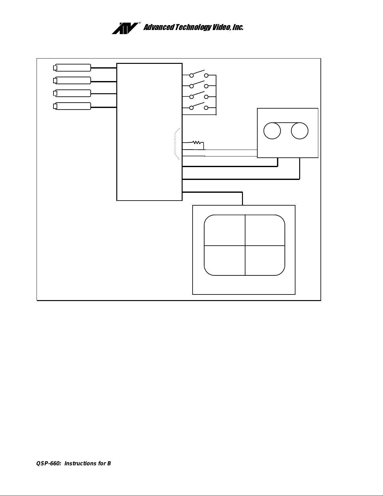
Advanced Technology Video, Inc.
Camera
Camera
Camera
Camera
QSP-660
Optional for VCR
recording
changes
VCR-IN
VCR OUT
VIDEO OUT
(Optional)
10K
Configuration
Alarm Inputs
Alarm Out
VCR
OUT
IN
Monitor
The above diagram shows the typical 4-camera installation for the QSP-660. Up to four cameras can be
connected to the real time quad using the back panel connectors.
: The VCR and monitor connections must be as shown above for proper operation.
Note
Installation Steps
The following steps should be followed to ensure proper connection and set up of your QSP-660.
A diagram showing the overall connection configuration of the QSP-660 is shown above.
The installation steps are:
1. Connect your cameras, monitor, and VCR (if recording is necessary) to the QSP-660. Refer to
the “Back Panel Connections” and “Video Line Termination Switches” section on page 5 for
proper connections and switch settings for your particular installation.
2. Power up the QSP-660, then enter the QSP-660 set up menus by pressing and holding the
DISPLAY
manual starting on page 8. Set the current time and date in the QSP-660 using the
Time/Date
3. Exit the QSP-660 menus by pressing the
menu system.
QSP-660: Instructions for Basic Operation and Installation
button for approximately 3 seconds. Refer to the
menu.
DISPLAY
Set Up
button to exit each menu and finally the
menus section of the
Set
Page 4
Advanced Technology Video, Inc.
4. If your VCR has internal on-screen menus for its set up, use the
VCR Bypass
feature of the
QSP-660 to view the VCR’s on-screen menus on the display monitor. See the “VCR Bypass
Function” description on page 3.
5. At this point, the basic configuration of your QSP-660 is complete. You may now proceed to set
more advanced functions as required for your installation (alarms, camera labels, etc.) Refer to
the
Advanced Function menus
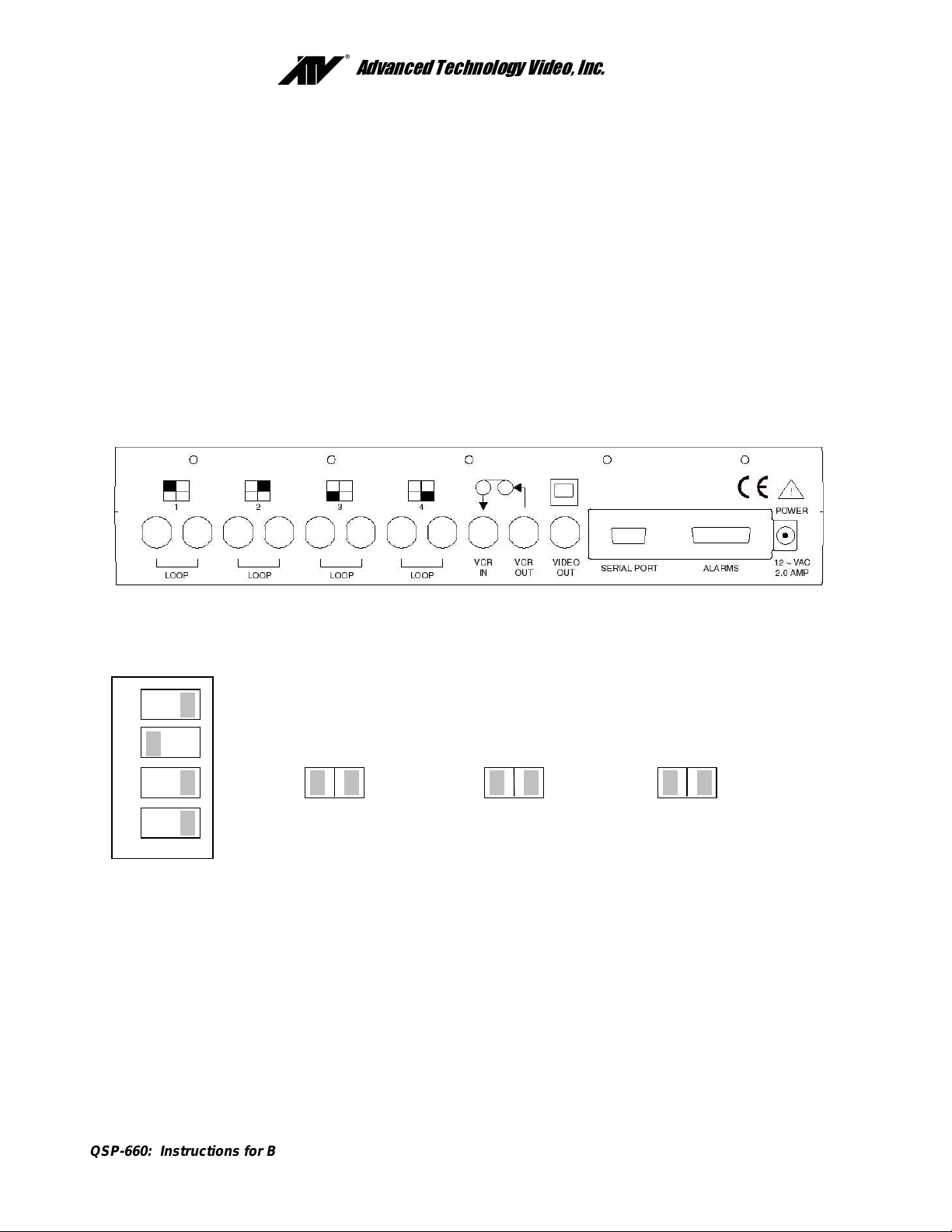
ACK PANEL CONNECTIONS
B
starting on page 9 for detailed information.
The four-camera input BNC connectors are labeled LOOP and the factory default configuration is 75 ohm
termination ON. One DIP switch and three jumpers inside the unit (see section below) determine whether each
inputs’ 75 ohm termination is ON or OFF.
Connect the QSP-660 VCR IN to the video output of the VCR and the QSP-660 VCR OUT to the video input of
the VCR. The alarm connector is a standard DB-15, which will mate with the included alarm wire adapter board
or standard computer-type cable. See page 18 for further alarm connection information.
IDEO LINE TERMINATION SWITCHES
V
1
2
3
4
SW4
Unused*
Unused*
Camera 4
VCR
JP3
Camera 3
Camera 2
JP2 JP1
Camera 1
*This switch must be in the position shown for proper QSP-660 operation.
The video line termination switches/jumpers for each camera input are located in the rear of the unit and are
accessed by removing the top cover. The switches/jumpers are in the order shown above when looking down
on the circuit board. The above switches/jumpers are shown in the factory default settings (75 ohm terminations
ON).
There is an additional termination switch for the VCR input on position 4 of SW 4.
Note:
QSP-660: Instructions for Basic Operation and Installation
Page 5
Advanced Technology Video, Inc.
O
PERATION
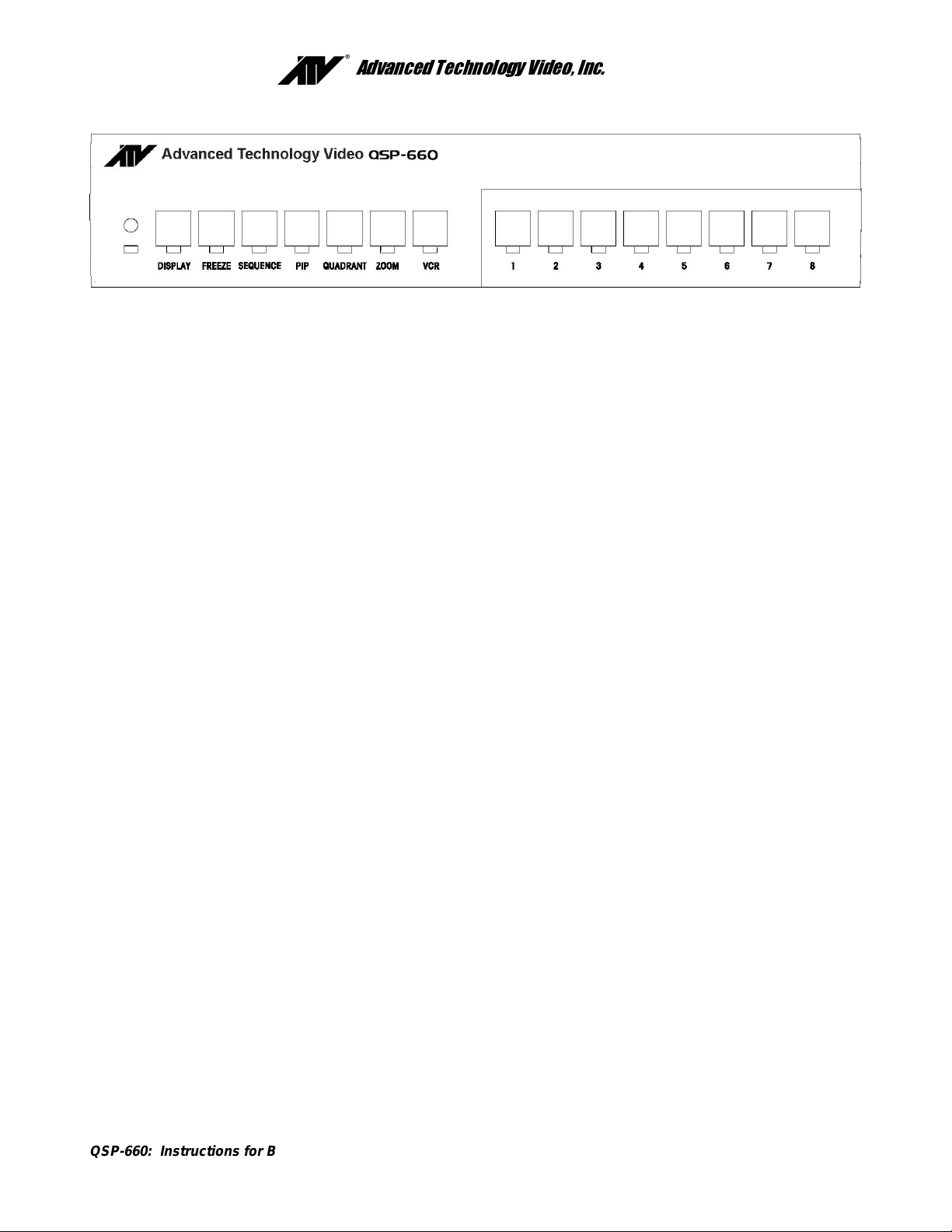
Your QSP-660 has seven mode control buttons and four numbered camera buttons which allow easy access to
all modes of operation. The seven mode buttons on the left are used to control monitor display operations and
VCR playback. An LED below each button will light when the unit is in the mode corresponding to that button.
: Live camera display modes
Note
affect recording. Following is a summary of each button’s
will
function and the QSP-660 operating modes.
DISPLAY
During live mode, this button selects the quad display. It will also return the unit to the quad display mode from
any other (non-quad) display mode. A push and hold of this button for approximately 3 seconds will bring up the
QSP-660 set up main menu.
FREEZE
In all display modes a press of this button will freeze the camera image(s) on the monitor display (the output to
the VCR recording is also frozen in this case). Another push of this button will deactivate the freeze mode.
SEQUENCE
A button press will activate the camera sequencing for the live mode. Another push of this button will deactivate
the sequencing mode. The default camera hold time is 3 seconds.
PIP
When starting in the quad or full screen camera display in live display mode, pressing the
Picture) button will cause the unit to switch to the Single PIP display. Additional presses will cycle the unit
through Dual PIP, Split Screen, Squish Screen, Full Frame and back to Single PIP displays.
QUADRANT
This button rotates the orientation of the cameras clockwise on the screen into the desired positions in PIP, Dual
PIP, Split Screen, and Squish Screen display modes.
ZOOM
The ZOOM function will expand a quadrant of any image in playback mode. Repeated presses of this button will
rotate through the quadrants.
VCR
Pressing this button will switch monitor display from the live camera display mode to the VCR playback mode.
The LED indicator will light to show that VCR playback is now possible.
VCR Bypass Function.
The VCR Bypass function is activated by a long button press of the
While in VCR Bypass mode, the QSP-660 will pass the VCR output directly to the monitor. A single push of the
button will return the unit to normal VCR playback mode and a second push will return the unit to live
VCR
display mode.
CAMERA Buttons (1 Through 4)
The individual camera buttons 1 through 4 are used to select which camera is to be used for display purposes
during live display modes and as zoom in playback. In addition, camera buttons 1 through 4 are also used in the
QSP-660 set up menus.
button for approximately 3 seconds.
VCR
(Picture-in-
PIP
QSP-660: Instructions for Basic Operation and Installation
Page 6

Advanced Technology Video, Inc.
R
EMOTE CONTROL OPERATION
The IR remote control provided with your QSP-660 has a limited set of buttons. Operation with the remote
control is slightly different than the front panel. The remote control has a single CAMERA button for selecting
cameras and successive button presses will rotate through the available cameras. Sequencing is initiated by
pressing and holding the remote control’s FREEZE button for approximately 3 seconds. Pressing the
QUADRANT button anytime in VCR playback accesses the ZOOM function.
Menus are not available through the remote control. The remote control must be
Note:
programmed when the batteries are removed. See “Programming Your ATV QSP-660 Remote
Control” on page 17.
QSP-660: Instructions for Basic Operation and Installation
Page 7
 Loading...