

INSTALLATION
INSTRUCTIONS
Table Of Contents
SEP Unit Dimensions . . . . . . . . . . . . . . . . . . . . . . . . . . . . 2
Shipping . . . . . . . . . . . . . . . . . . . . . . . . . . . . . . . . . . . . . . 3
Optional Accessories . . . . . . . . . . . . . . . . . . . . . . . . . . . . 3
CSA Requirements in USA . . . . . . . . . . . . . . . . . . . . . . . . 4
CSA Requirements in Canada . . . . . . . . . . . . . . . . . . . . . 4
Additional Requirements . . . . . . . . . . . . . . . . . . . . . . . . . 5
Unit Heater Installation . . . . . . . . . . . . . . . . . . . . . . . . . . . 5
Combustion and Ventilation Air . . . . . . . . . . . . . . . . . . 5
Rotation of Combustion Air Inducer . . . . . . . . . . . . . . . . . 5
Venting . . . . . . . . . . . . . . . . . . . . . . . . . . . . . . . . . . . . . . . 6
Electrical Connections . . . . . . . . . . . . . . . . . . . . . . . . . . . 11
Typical SEP Wiring Diagram . . . . . . . . . . . . . . . . . . . . . . 11
Gas Connection . . . . . . . . . . . . . . . . . . . . . . . . . . . . . . . . . 12
Leak Check . . . . . . . . . . . . . . . . . . . . . . . . . . . . . . . . . . . . . . 12
SEP
100,000 to 400,000 Btuh Series
UNIT HEATERS
IM-SEP-0652453-07
November 2011
Supersedes 65245306
Unit Start−Up . . . . . . . . . . . . . . . . . . . . . . . . . . . . . . . . . . . . . . 12
To Turn Off Gas to Unit . . . . . . . . . . . . . . . . . . . . . . . . . . . . . . 14
Heating Sequence of Operation . . . . . . . . . . . . . . . . . . . . . . . . 14
Ignition Control LED . . . . . . . . . . . . . . . . . . . . . . . . . . . . . . . . . 14
High Altitude Adjustment . . . . . . . . . . . . . . . . . . . . . . . . . . . . . 14
Gas Flow . . . . . . . . . . . . . . . . . . . . . . . . . . . . . . . . . . . . . . . . . 16
Gas Pressure Adjustment . . . . . . . . . . . . . . . . . . . . . . . . . . . . 16
Limit Control Switch . . . . . . . . . . . . . . . . . . . . . . . . . . . . . . . . . 16
Louver Vane Adjustments . . . . . . . . . . . . . . . . . . . . . . . . . . . . 16
Combustion Air Pressure Switch . . . . . . . . . . . . . . . . . . . . . . . 16
Service . . . . . . . . . . . . . . . . . . . . . . . . . . . . . . . . . . . . . . . . . . . 16
Start−Up and Performance Checklist . . . . . . . . . . . . . . . . . . . . 17
Template . . . . . . . . . . . . . . . . . . . . . . . . . . . . . . . . . . . . . . . . . . 18
Warranty . . . . . . . . . . . . . . . . . . . . . . . . . . . . . . . . . . . . . . . . . . 19
RETAIN THESE INSTRUCTIONS
Failure to follow safety warnings
exactly could result in serious injury,
death, or property damage.
Be sure to read and understand the
installation, operation and service instructions in this manual.
Improper installation, adjustment, alteration, service or maintenance can cause
serious injury, death or property damage.
Do not store or use gasoline or other
flammable vapors and liquids in the vicinity of this or any other appliance.
Installation and service must be per-formed
by a qualified installer, service agency or
the gas supplier.
FOR FUTURE REFERENCE
WARNING
FIRE OR EXPLOSION HAZARD.
WHAT TO DO IF YOU SMELL GAS:
• Do not try to light any appliance.
• Do not touch any electrical switch; do not use
any phone in your building.
• Leave the building immediately.
• Immediately call your gas supplier from a
neighbor’s phone. Follow the gas supplier’s instructions.
• If you cannot reach your gas supplier, call the fire
department.
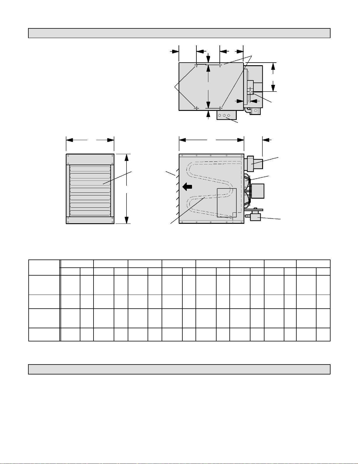
SEP Unit Dimensions
*7-5/8
1/2
D
(194)
FOR UNIT SUSPENSION
Additional
mounting nuts
F
furnished on
E
SEP−250,
SEP−300,
SEP−345 and
G
SEP−400 models
FLUE
only.
OUTLET
(13)
ELECTRICAL INLETS
TOP VIEW
A
H
INDUCER
LOUVERS
DIRECT
AIR
DRIVE FAN
FLOW
GAS
HEAT
VALVE
EXCHANGER
A B C D E F G H
Unit
in.
mm
in.
mm
in.
mm
in.
mm
in.
mm
in.
mm
in.
mm
in.
mm
SEP-100
SEP-115
31-5/16
795
32-3/16
817
20-3/16
512
11-1/2
292
19-1/16
484
11-3/4
298
3-1/4
83
7-7/8
200
SEP−145
SEP−175
31-5/16
795
32-3/16
817
23-1/8
588
11-1/2
292
22-1/16
560
8−1/2
216
3-1/4
83
8−11/16
220
SEP−200
SEP-230*
SEP−250*
31-5/16
795
32-3/16
817
41-1/8
1045 3-11/16
97
40
1016
17-3/4
451
3-1/2
89
8-11/16
220 SEP−300*
31-5/16
795
32-3/16
817
41-1/8
1045 3-11/16
97
40
1016
17-1/2
445
3-1/2
89
9-13/16
248
SEP−400*
2
NOTE – SEP models 100, 115, 145, 175 and 200
have a single fan. SEP models 230, 250, 300, 345
and 400 have two fans.
NOTE – Two mounting nuts are furnished on
SEP models 100, 115, 145, 175 and 2 00. F our
mounting nuts ar e f urnished on SEP models
230, 250, 300, 345 and 400 models.
SEP−230,
(13)
1/2
3/8" x 16 MOUNTING NUTS
C
COMBUSTION AIR
ADJUSTABLE
B
END VIEW
SIDE VIEW
SEP-345*
*Unit contains dual fans.
Shipping
The heater is completely assembled and is shipped with installation and operating instructions, warranty certificate
and flue transition. Check the unit for shipping damage. The receiving party should contact the last carrier
immediately if any shipping damage is found.
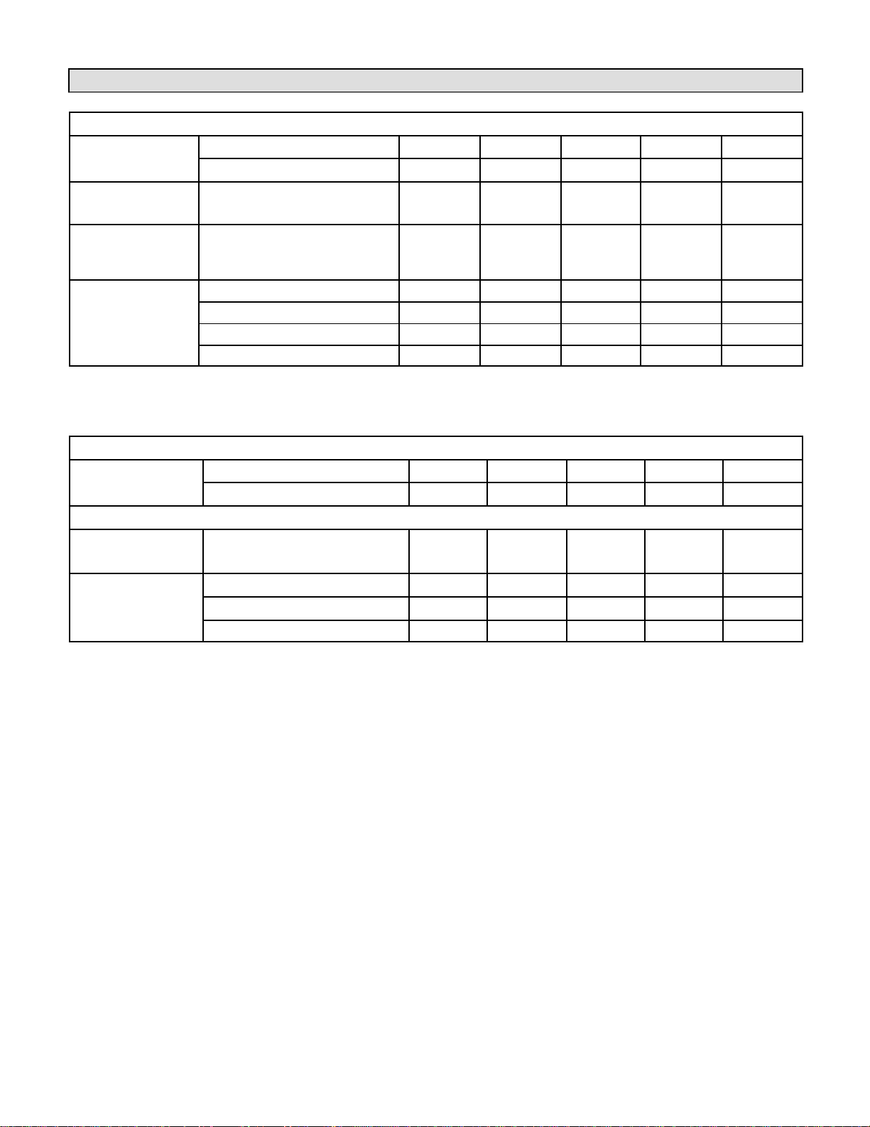
Optional Accessories
SEP−100 to SEP−230
Gas Part No. − Stainless Steel
SEP−100S
SEP−115S
SEP−145S
SEP−175S
SEP−200S
Heating
Performance
Part No. − Aluminized Steel
SEP−100A
SEP−115A
SEP−145A
SEP−175A
SEP−200A
Hanging Bracket
100001381
X X X X X
Kit
High Altitude
Pressure Switch
176722600
X 1
X 1
X 1
X 2
− − −
Kit
165296401
X
LPG/Propane Kit
165295202
X X X
165295205
X
165295203
SEP−230 to SEP−400
Gas Part No. − Stainless Steel
SEP−230S
SEP−250S
SEP−300S
SEP−345S
SEP−400S
Heating
Performance
Part No. − Aluminized Steel
SEP−230A
SEP−250A
SEP−300A
SEP−345A
SEP−400A
Optional Accessories − Must Be Ordered Extra
Hanging Bracket
100001381
X X X X X
Kit
165296403
X
X
LPG/Propane Kit
165295203
X
X
165295206
X
3
TABLE 1
1
SEP−100 through −145 require replacement combustion air inducer pressure switch at altitudes over 5500 feet above sea level.
2
SEP−175 requires replacement combustion air inducer pressure switch at altitudes over 2500 feet above sea level.
TABLE 2
Top
Sides
Bottom
Rear
Flue
in
mm
in
mm
in
mm
in
mm
in
mm
0 18
Combustible materials that are affected by
units can approach 200°F.
4
CSA Requirements in USA
Installation of gas unit heaters must conform with local
building codes or, in the absence of local codes, with the
current edition of ANSI−Z223.1, National Fuel Gas Code.
Installation in aircraft hangers must be in accordance with
the current edition of ANSI/NFPA No. 409, Standard for
Aircraft Hangers.
Installation in parking structures must be in accordance
with the current edition of ANSI/NFPA No. 88A,
Standard for Parking Structures.
Installation in repair garages must be in accordance
with the current edition of ANSI/NFPA No. 88B,
Standard for Repair Garages.
Authorities having jurisdiction should be consulted
before installation. Air for combustion and ventilation
must conform to the methods outlined in the current
edition of ANSI Z223.1, Section 5.3, Air for Combustion
and Ventilation, or applicable provisions of local
building codes.
The National Fuel Gas Code (ANSI-Z223.1) is
available from:
These units are CSA international design−certified. These
unit heaters are certified for clearances to combustible
material as listed in table 1 and on unit rating plate.
Accessibility and service clearances must be observed
in addition to fire protection clearances.
All electrical wiring and grounding for unit must be in
accordance with the regulations of the current edition of
ANSI/NFPA No. 70, National Electric Code.
The National Electric Code is available from:
American National Standard Institute Inc.
11 West 42nd Street
New York, NY 10036
National Fire Protection Association
1 Batterymarch Park
PO Box 9101
Quincy, MA 02269−9101
CSA Requirements in Canada
These instructions are intended only as a general guide
and do not supersede local codes in any way.
Authorities having jurisdiction should be consulted
before installation. The installation must conform with
local building codes or, in the absence of local codes,
with the current edition of CSA-B149 installation
compliance codes. All electrical wiring and grounding
for the unit must also comply with the current edition of
CSA C22.1, Canadian Electrical Code.
These unit heaters are CSA-certified for clearances to
combustible material listed on the rating plate and table
3. Adequate clearance must be provided around the
appliance and around air openings into the combustion
chamber. Provision must be made for service
accessibility.
NOTE: Fire protect ion clearances may be exceeded to
provide additional space for service and accessibility.
UNIT CLEARANCES TO COMBUSTIBLE MATERIALS
6 152 6 152 0
TABLE 3
457 6 152
GARAGE / WAREHOUSE INSTALLATIONS
1 − In a storage area, clearance from the heater to
combustible materials must be such that the
combustible material must not attain a
temperature above 160°F (71°C) during
continuous operation of the unit.
WARNING
exposure to temperatures less than 160°F
(plastics, plastic wrap, styrofoam, cardboard,
etc.) must be stored well away from this
heater. Discharge air temperatures for these
2 − Maintain an 8−foot (2.5 m) minimum clearance
from the floor to the bottom of the heater. Refer to
the current edition of CSA-B149 installation
compliance codes.
1 − In an area where aircraft are housed or serviced, a
10−foot (3 m) minimum clearance from the highest
surface of the aircraft to bottom of the heater must
be maintained.
2 − In other areas, an 8-foot (2.5m) minimum
clearance from the floor to bottom of heater must
be maintained.
3 − Heaters should be located so that they are
protected from damage from aircraft or other
appliances needed for servicing of aircraft. Refer
to requirements of the enforcing authorities.
In a confined area, the heater must be installed in
accordance with the current edition of CSA-B149
installation compliance codes. Be sure to check with
local codes and ordinances for additional requirements.
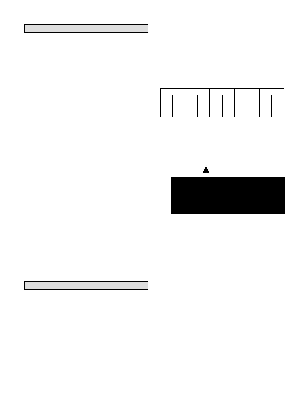
AIRCRAFT HANGER
Model Number
Feet (Meters)
SEP−100 and SEP−115
16 (4.9)
SEP−145, SEP−175, and
20 (6.1)
SEP−200
SEP−230, SEP−250,
SEP−300, SEP−345 and
30 (9.1)
SEP−400
Improper installation, adjustment, alteration, ser-
agency or the gas supplier.
As with any mechanical equipment, personal
equipment.
Do not use the gas manifold pipe to lift unit. Any
misaligned.
Insufficient combustion air can cause headaches,
nausea, dizziness, asphyxiation or death.
5
Additional Requirements
The Commonwealth of Massachusetts stipulates the
following additional requirements:
1 − Gas furnaces shall be installed by a licensed
plumber or gas fitter only.
2 − The gas cock must be T handle" type.
Unit Heater Installation
WARNING
vice or maintenance can cause property damage,
personal injury or loss of life. Installation and
service must be performed by a licensed
professional installer (or equivalent), service
CAUTION
injury can result from contact with sharp sheet
metal edges. Be careful when you handle this
The appliance shall not be installed downstream from
evaporator coils or cooling units.
Install the unit in the desired location as governed by
clearances, vent connection, air direction, gas supply,
electrical supply and service accessibility.
On SEP models 100, 115, 145, 175, and 200, mounting
nuts are furnished at the balance point (two positions
only). On SEP models 230, 250, 300, 345 and 400,
mounting nuts are furnished at each corner of the unit.
Mounting nuts will accommodate 3/8" x 16 threaded rods.
1 − Cut threaded rods to desired length and slide a
3/8" nut onto the rod.
2 − Slide a flat washer onto the threaded rod AFTER
the nut (7/16" inside diameter X 1" outside
diameter X 1/16" thick washer).
3 − Screw the rods (two or four) into the mounting
nuts on the unit.
4 − Tighten nuts to secure unit to rods.
IMPORTANT
excessive upward or downward force on the
manifold pipe and bracket assembly can cause
the ignition burner and igniter to become
MAXIMUM MOUNTING HEIGHTS
TABLE 4
Combustion and Ventilation Air
Adequate facilities for supplying air for combustion and
ventilation must be provided in accordance with the
current edition of ANSI Z223.1, section 5.3, and
CSA−B149 installation compliance codes, or applicable
provisions of local building codes.
All gas−fired appliances require air to be used for the
combustion process. In many buildings today, there is a
negative indoor air pressure caused by exhaust fans, etc.
If sufficient quantities of combustion air are not
available, the heater or another appliance will operate
in an inefficient manner, resulting in incomplete
combustion which can result in the production of
excessive carbon monoxide.
CAUTION
If indoor air is to be used for combustion, it must be free
of the following substances or the life of the heat
exchanger will be adversely affected: chlorine, carbon
tetrachloride, cleaning solvent, halogen refrigerants,
acids, cements and glues, printing inks, fluorides, paint
removers, varnishes, or any other corrosives.
Rotation of Combustion Air Inducer
(SEP−100, −115 and −145 Only)
The combustion air inducer on SEP models −100, −115
and −145 may be rotated 90° either to the left or right of
the original vertical position in order to better suit the
application.
NOTE − It is not permissible to rotate the combustion
air inducer on SEP models −175, −200, −230, −250,
−300, −345 and −400.
Rotate the combustion air inducer assembly as follows:
1 − Remove the heater from the carton. Decide the best
unit heater orientation. The vent can be installed in
one of three discharge positions: up, left, or right.
2 − If the inducer is to be rotated, follow the
6
instructions in this section; otherwise, refer to
instructions under Venting" section.
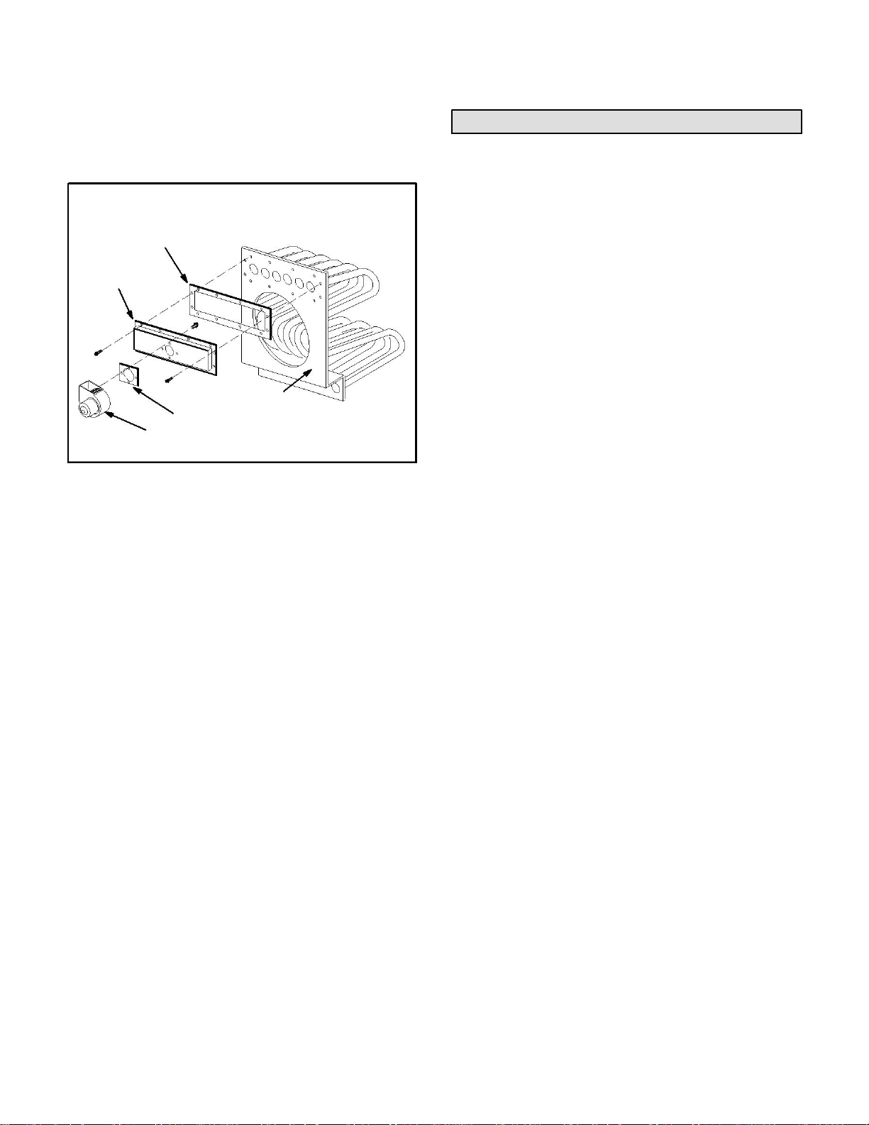
3 − Before making an electrical or gas connections,
remove the securing screws on the flue
box/combustion air inducer. See figure 1.
FLUE BOX AND
COMBUSTION AIR INDUCER ASSEMBLY
FLUE BOX GASKET
FLUE BOX
COMBUSTION AIR INDUCER
VEST PANEL
COMBUSTION AIR INDUCER GASKET
4 − Remove the flue box/combustion air inducer
assembly, ensuring that the gasket is not
damaged. If the gasket is damaged, replace it.
5 − Use a 1/4" socket to remove the three screws
which secure the combustion air inducer to the
flue box.
Remove the inducer and gasket from the flue box
ensuring that the gasket is not damaged. If the
gasket is damaged, replace it.
6 − Use the template provided in the back of this
manual to mark new hole locations. Use a 7/32"
drill bit to drill holes in flue box.
7 − Place the gasket between the combustion air
inducer and the flue box. Rotate both the inducer
and the gasket 90° to the desired position.
Reinsert and tighten the three inducer securing
screws
(#8−16 X 1/2" HWHSMS).
8 − Place the gasket between the flue box and the
vest panel. Position the flue box/combustion air
inducer assembly on the vest panel. Fasten the
flue box to the vest panel using the flue box
securing screws (#10−16 X 5/8" HWHSMS) and a
5/16" driver.
FIGURE 1
9 − The unit heater is now ready for installation as
described in the Venting section.
Venting
NOTE − The vent is a passageway, vertical or nearly
so, used to convey flue ga ses from an applianc e, or its
vent connector, to the outside atmosphere. The vent
connector is the pipe or duct that connects a fuel-gas
burning appliance to a vent or chimney.
NOTE − Local codes may supersede any of these
provisions.
GENERAL RECOMMENDATION AND
REQUIREMENTS
SEP unit heaters must be vented in compliance with
the latest edition of the National Fuel Gas Code (NFPA
54 / ANSI Z223.1) in the USA and with CSA-B149.1
codes in Canada, as well as applicable provisions of
local building codes, and the following instructions.
A sheet metal flue transition is supplied with this
certified unit. It must not be modified or altered and
must be installed on the outlet of the combustion
air inducer assembly prior to the installation of the
vent connector. Failure to comply with this
requirement will void the certification of the unit by
the approval agencies.
A single-wall vent connector may be used in all
applications between the furnace and the vertical vent
pipe.
A single−wall vent pipe used as a vent connector or as
a vertical vent, must have all seams and joints sealed
with pressure-sensitive aluminum tape or silicone
rubber sealant. Aluminum tape must meet the
provisions of SMACNA AFTS−100−73 Standards. The
aluminum tape must have a temperature rating of
400°F (204°C).
Silicone rubber sealant must have a temperature rating
of 482°F (250°C), i.e., Dow Corning RTV−736 or
equivalent.
All joints must be secured with at least two corrosion
resistant screws. All joints must be checked for gas
tightness after installation. Single-wall vent pipe used
as vertical vent must not pass through any attic, interior
wall, concealed space, or floor.
 Loading...