

Advanced Distributor Products HX Installation Manual
adp.feedback@adpnow.com
**Large Tonnage A & H Coils (greater than 5 Tons) are not AHRI Certified
*
front
Slab Coil
Top Connection
Side Connection
Coil
**
Part # 96654008
Evaporator Coil Installation Instructions
A-Coil
Page 4
Multi-position A-
Page 4 - 7
Page 5
Horizontal A-Coil
Page 5
Horizontal A-Coil
July 2010
Page 5
PRODUCT IMPROVEMENT IS A CONTINUOUS PROCESS AT ADVANCED DISTRIBUTOR PRODUCTS. THEREFORE, PRODUCT
SPECIFICATIONS ARE SUBJECT TO CHANGE WITHOUT NOTICE AND WITHOUT OBLIGATION ON OUR PART. PLEASE CONTACT
YOUR ADP REPRESENTATIVE OR DISTRIBUTOR TO VERIFY DETAILS. © BY ADVANCED DISTRIBUTOR PRODUCTS. ALL
* Only applies to C-Series upflow/downflow cased A-Coil
RIGHTS RESERVED.
ADP evaporator coils are designed for use with condensing units or heat pump units. These instructions are intended as a
general guide and do not supersede local codes in any way. Consult with local authorities having jurisdiction before
installation. Read this installation manual and all “Warning” statements prior to installing the evaporator coil.
Check coil for shipping damage and verify the contents of the box containing the evaporator coil. If you should find damage,
immediately contact the last carrier. Verify the efficiency requirements are appropriate with the matched condensing or heat
pump units such as capacity, SEER, EER, and/or HSPF. Check outdoor unit manufacturer for proper line sizing. It is
recommended that the coil be washed with a coil cleaner to remove any residual oil that may have been left from the
manufacturing process. Coils are shipped with a 10 psi dry air holding charge. Puncture rubber plug on suction line
to release charge before removing plugs. The absence of pressure does not verify a leak. Check the coil for leaks before
installing or returning it to your wholesaler.
Position the coil on the outlet of the furnace using sheet metal screws. Drain pans are made of a polymer that can withstand
temperatures up to 450 deg. F. Maintain a 3” clearance on oil or drum type heat exchangers and 1½” on sectionalized
heat exchangers. Coil should be level, or pitched slightly toward the drain connection. Airflow face velocity above 350
ft/min. is not recommended for downflow or counterflow applications due to potential water blow-off. Refer to
Engineering & Specification Guide for limitations.
2175 West Park Place Blvd., Stone Mountain, GA 30087
panel
***
GENERAL
www.adpnow.com
1
REFRIGERANT METERING
R-22 TXV Part #s
R-410A TXV Part #s
18-36 MBTUH Bleed A/C
65540600
18-36 MBTUH Non-Bleed A/C
65026401
42-60 MBTUH Bleed A/C
65540700
42-60 MBTUH Non-Bleed A/C
65026400
18-36 MBTUH Non-Bleed A/C
99167501
18-36 MBTUH Non-Bleed A/C-HP
65616601
42-60 MBTUH Non-Bleed A/C
99167502
42-60 MBTUH Non-Bleed A/C-HP
65616602
18-36 MBTUH Non-Bleed A/C-HP
65616201
42-60 MBTUH Non-Bleed A/C-HP
65616202
Teflon O-Ring Seal
Figure 1
Coils are suited for R-22 and R-410A refrigerants and can be used with or without a TXV. Replacement TXV part numbers
are listed below; see kit instructions for change out or installation. ADP recommends placing a wet rag around the suction
line at the cabinet during brazing to prevent overheating and damaging the sensing bulb. For optimum performance, the bulb
should be reattached outside of the cabinet to the main suction line no more than one foot from the suction line connection
and positioned on the suction line at 9 or 3 O’clock and insulated. When changing a system from AC to heat pump or heat
pump to AC check the current TXV specifications to determine if a TXV replacement is required. If the evaporator coil
contains a Non-Bleed TXV and is used with a condensing unit containing a reciprocating compressor, a hard start
mechanism will be required on the outdoor unit.
Large Tonnage A-Coils of 7.5 Ton (R-410A) cooling capacity include an adjustable TXV that can be used to fine tune
superheat. Turn adjustment clockwise to increase superheat 4°F per turn and counterclockwise to decrease superheat 4°F
per turn. To return to factory setting, turn adjustment stem counterclockwise until the spring is completely unloaded (reaches
stop or starts to “ratchet”). Then, turn it back 6 “Total Turns”.
! IMPORTANT !
When changing the expansion valve, the TXV MUST match the refrigerant type and capacity of the condensing unit. Failure
to do so will result in poor performance and possible compressor damage. All coils must be matched properly as listed in the
AHRI directory.
Cased coils with piston florator assemblies are shipped with a cap and nut over the threaded fitting. Remove the cap and nut
slowly, allowing charge to escape, and secure the liquid line stub (attached to cabinet) to the florator assembly with nut.
Discard cap.
For optimum performance, the piston should be sized to
match the recommendation from the outdoor unit manufacturer.
If the outdoor unit manufacturer does not recommend a piston size
refer to the piston-sizing chart on page 3.
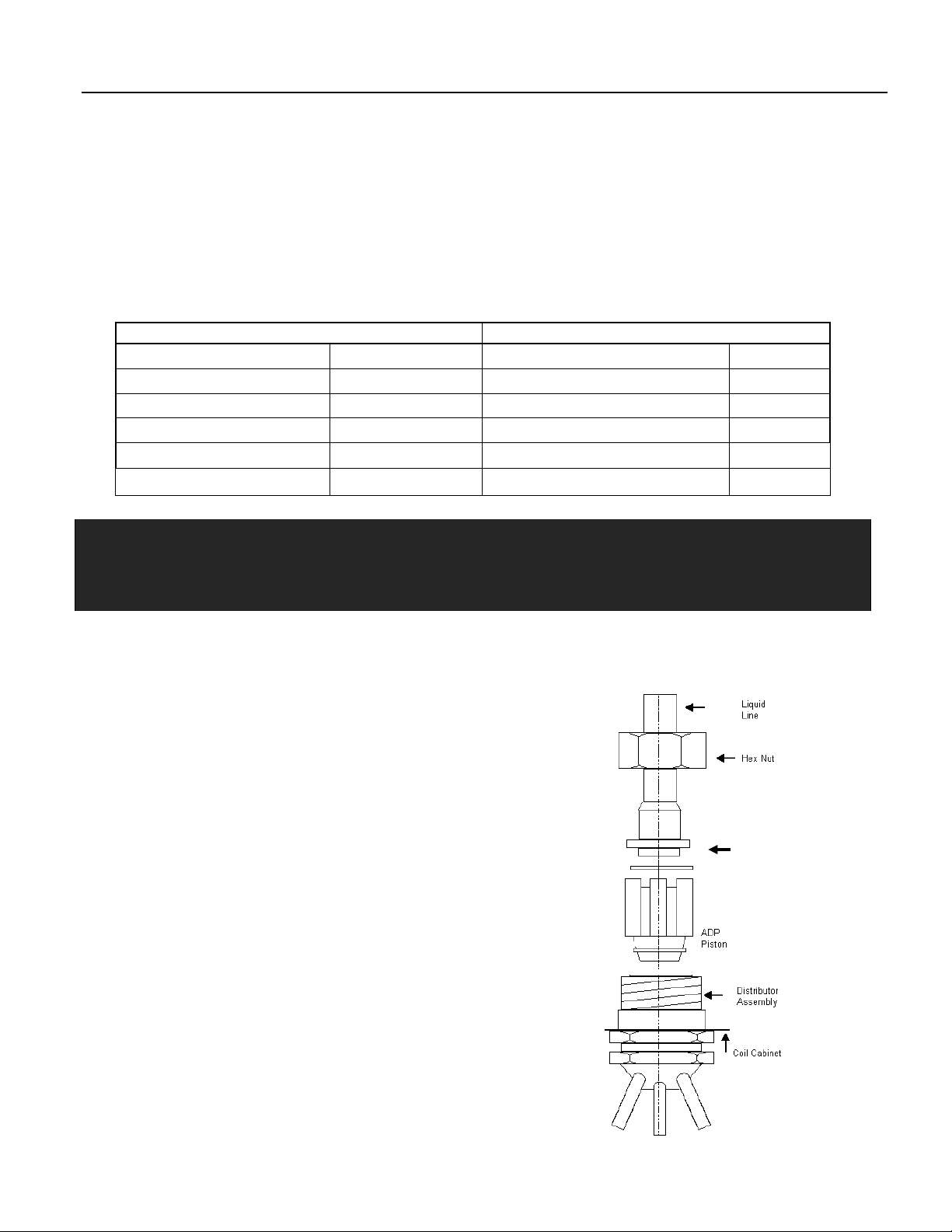
When changing ADP florator pistons refer to the Figure 1 and
use the following procedure:
1. Loosen hex nut located on liquid line and separate
from distributor assembly.
2. Remove the existing piston from inside the distributor
assembly.
3. Insert the desired ADP piston into the distributor
assembly.
4. Inspect Teflon O-Ring and replace if damaged.
Ensure Teflon O-Ring is in place.
5. Re-install florator nut to body and torque to 10 ft-lbs.
2
Florator Piston Size
R-22
R-410A
Ton
Piston
Size
Part #
Piston
Size
Part #
1 41
100000035
41
100000035
1.5 53
100000036
49
100000049
2 59
100000037
53
100000036
2.5 67
100000039
59
100000037
3 73
100000041
67
100000039
3.5 80
100000044
73
100000041
4 84
100000045
76
100000042
5 93
100000047
93
100000047
Figure 2
CONDENSATE DRAIN
Coils are equipped with multiple drain connections. Determine the drain connections to be used and note the difference
between the primary (green) and secondary (red) openings. Drain plugs are provided for all openings, remove and discard
the appropriate plugs with ½” drive ratchet and verify that remaining plugs are tight. (2.5 ft-lbs) Attach drain line to pan with ¾
“ male pipe thread PVC fittings. Hand tight is adequate - Do not over tighten & do not reduce drain line size!
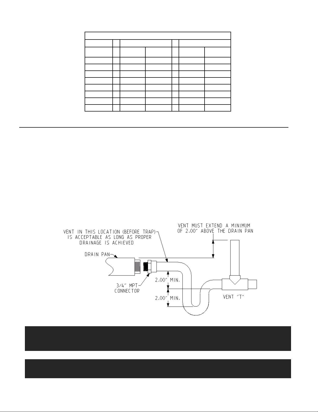
Route drain(s) line so they will not be exposed to freezing temperatures and do not interfere with accessibility to the coil, air
handling system or filter. The drain should be pitched downward 1” per 10’ with a 2” trap as close to the coil as possible. If line
makes a second trap, or has an extended run before termination, a vent tee should be installed after the trap closest to the
pan. See Figure 2.
If the coil is located in or above a living space where damage may result from condensate overflow, a separate ¾” drain must
be provided from the secondary drain connection. Run this drain to a place in compliance with local installation codes where it
will be noticed when unit is operational. Condensate flowing from the secondary drain indicates a plugged primary drain.
Prime the trap with water. Test line for leaks. Test water flow with unit in operation. An auxiliary drain pan should also be
installed under the unit as specified by most local building codes.
! WARNING !
Product contains fiberglass wool. Disturbing the insulation in this product during installation, maintenance or repair will
expose you to fiberglass wool. This material may cause respiratory, skin, and eye irritant. Breathing this may cause lung
cancer. (Fiberglass wool is known to the State of California to cause cancer.)
IMPORTANT
The Clean Air Act of 1990 bans the intentional venting of refrigerant (CFC’s and HFC’s). Approved methods of reclaiming
must be followed. Fines and/or incarceration may be levied for non-compliance.
3
 Loading...