

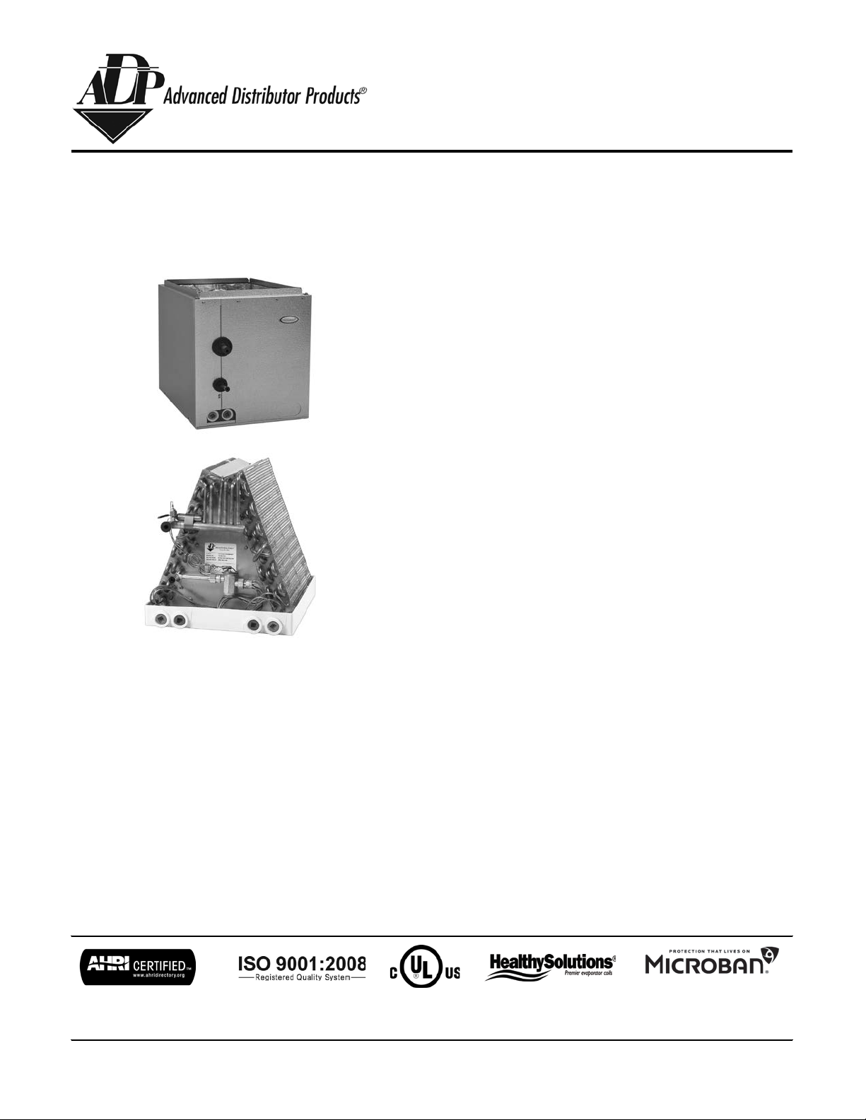
HE Series
Evaporator Coils
SG-HE-02
Specification Guide
Contents ..................................................... Page
HE Series A-Coils
Features ..................................................... 2
Nomenclature .............................................
3
Specifications.............................................. 4
Pallet Quantities ........................................ 12
Product improvement is a continuous process at Advanced Distributor Products. Therefore, product specifications are subject to change without notice
www.adpnow.com
March 2018
and without obligation on our part. Please contact your ADP representative or distributor to verify details.
© by Advanced Distributor Products. All rights reserved.
2175 West Park Place Blvd., Stone Mountain, GA 30087

HE Series – Product Features
• High efficienc y lanced fin design
• “No-hassle” 5 year warranty.
• R-22, R-410A, AC & Heat Pump compatible.
• All coils have durable packaging wit h bar coded labels on the box.
• Threaded expansi on valves available f actory install ed or as a field installed kit.
• Coils are air pr essure tested at 500 psi, l eak tested with heli um , sealed with rubber plugs, then charged wit h dry air.
• Piston options i nclude externally accessible body for eas y piston change out and/or TXV installati on.
• Microban® antimicrobial additive t o inhibit the growth of m old and mildew in the drain pan.
• UV resistant drain pans are molded of high t emperature (450 deg. F) engineered polymer .
• Dual 3/4" FPT condensate drains on front-left and front-right side of drain pans.
• Patented HydroTEC™ low water retention drain pan.
• Copper refrigerant connections for easy brazing on both cop per and aluminum slab models.
• Intertek lab tested 1% or less cabinet air leakage for better efficiency.
• Cased coil cabinets are fully lined with 5/8" foil faced insulation.
• Optional painted or embossed galvanized s teel cabinets.
• Short cabinet wit h easy access.
• Non-captive refrigerant lines with long stubs make for eas y installation.
• Enhanced refrigerant pipe grommets: secure, tight, and eas y to install.
• Copper distributor tube assem bly provides brass to brass threads for t rouble-free servic e of TXV.
• Expansion valve with improved temperature sensing:
1.) Mounted inside cabinet to prevent exter nal sweating
2.) Bulb clamped standard factory instal led
• All multi-position coils are upfl ow, d ownflow, and left or r ight airflow capable.
• Cabinet insulation hold down tabs f or easy drain pan removal.
• Interlocking doors reduce air leakage and allow for easy access.
• Foam drain seal for reduced air leakage.
• All multi-position coils are field convertible from horizontal right-to-left airflow and horizontal left
-to-right airflow.
• Suction line refrigerant connections are 3/4" ODF (A-Coil 18-36 size models) or 7/8" ODF (A-Coil 42-60 size models)
• Suction line refrigerant connections are 1.125" on slab numbers E43, E46, E56, and E65 for size 42 models and higher.
• Corrosion resistant coil header plates.
• All A-Coils are upflow or downflow capable.
WARNING—Face velocity above 350 ft/min. is not recommended for downflow or counterflow applications due to potential
water blow-off.
2

HE Series – Nomenclatu re
Cabinet Color
Piston Size
[3]
H = Embossed
AP = TXV access port
[4]
A = Armstrong
MBTUH R-22 R-410A
D = Ducane/Aire-Flo
G = ICP
J = Goodman/Amana
L = Lennox
N = Nordyne
P = Carrier/Bryant/Payne
R = Rheem/Ruud
T = Trane/American Std.
Y = York/Luxaire/Coleman
Product Code
[5]
Slab Number
00 = Right-hand uncased
E & A = Copper slab
01 = Right-hand cased
G = Aluminum s l ab
04 = Left-hand uncased
05 = Left-hand cased
Metering Device
[1]
20 = Right-hand cased multi-position
1 = Piston (R-410A)
22 = Left-hand cased multi -position
2 = Piston (R-22)
6 = Non-bleed A/C TXV (R-410A) Cabinet Height
[6]
7 = Bleed HP-A/C TXV (R-410A)
00 = Uncased
8 = Bleed A/C TXV (R-410A)
12 = 12.5"
9 = Non-bleed HP-A/C TXV (R-410A)
16 = 16.5"
18 = 18.5" (up to 31.5")
Nominal MBTUH
Cabinet Upper Notch
Cabinet Depth
[2]
A = Uncased
A = Uncased
D = 21.0"
B = .75" (standard)
C = 20.5"
E = 21.5"
Width
140 = 14"
130 = 13"
142 = 14.25"
140 = 14"
145 = 14.5"
155 = 15.5"
175 = 17.5"
170 = 17"
210 = 21"
200 = 20"
245 = 24.5"
205 = 20.5
255 = 25.5"
235 = 23.5"
251 = 25.1"
Uncased
60 =
939342 =
807348 =
847630 =
675936 =
736718 =
534924 =
59
53
1205AP
12 =
41
41
145HG30224
D
Cased
B
3
[1] 7 and 8 valve options available only for York family products.
[2] C-depth not available for aluminum slabs.
[3] Piston will always be sized to match the nominal BTU rating of the coil.
[4] TXV access port standard on factory installed TXVs; optional on piston models.
[5] Refrigerant connections and exposed drain connections are both on the left or right side as indicated.
[6] Cabinet height not a selectable option, see cased dimensions.
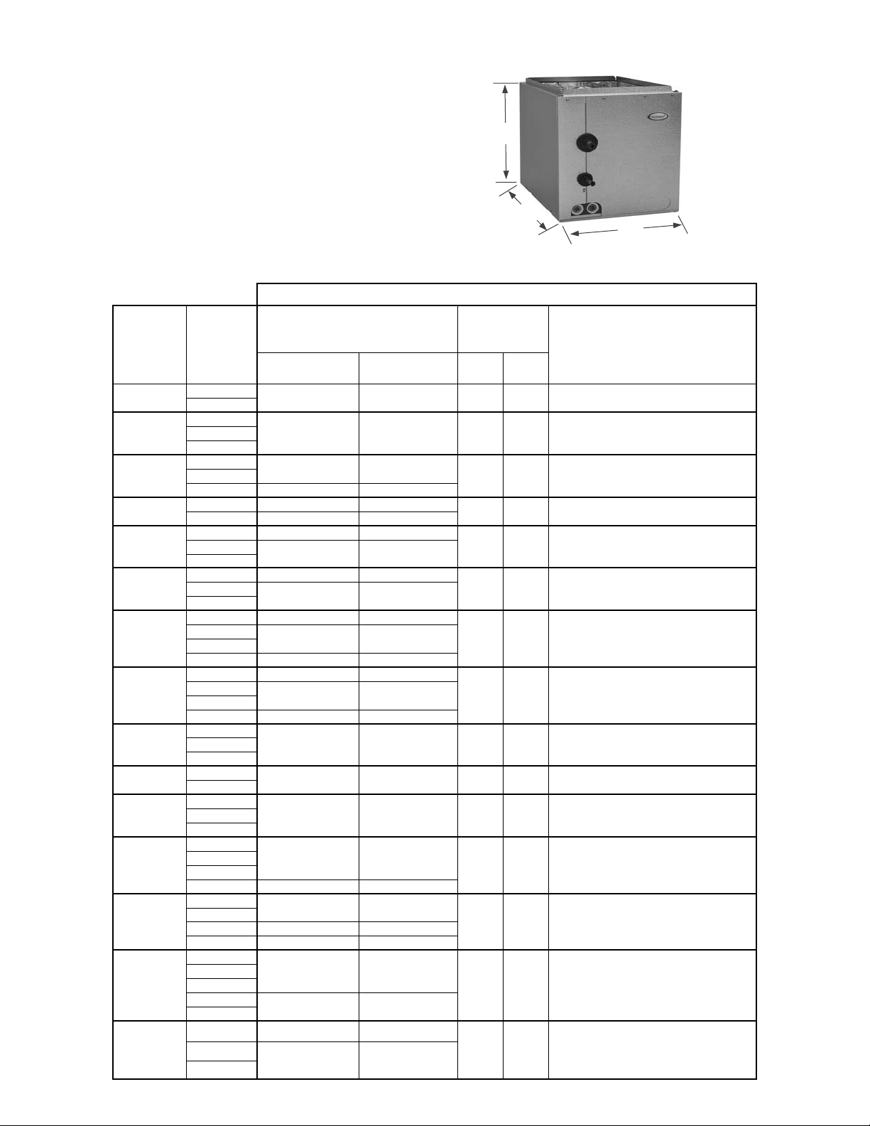
HE Series –
Cased Specifications
A = Width
Multi-
Pos
18241824302430
36 14.25" - 21.0" 14.5" - 21.0"
36 14.5" - 24.5" 14.5" - 24.5"
42 17.5" - 24.5" 17.5" - 24.5"
36 14.5" - 24.5" 14.5" - 24.5"
424836 14.25" - 24.5" 14.5" - 24.5"
424836 14.25" - 24.5" 14.5" - 24.5"
424860 21.0" - 24.5" 21.0" - 24.5"
36 ** 14.25" - 24.5" ** 14.5" - 24.5"
424860 21.0" - 24.5" 21.0" - 24.5"
4248601824182430182430
36 14" - 24.5" 14.5" - 24.5"
243036 14.25" - 24.5" 14.5" - 24.5"
42
17.5" - 24.5" 17.5" - 24.5"
2430364248
Cased Dimensions
** 16.5" height available in all col ors.
E depths only).
** 25.5" height available in all col ors.
E depths only).
B
A
4
B = Depth
C = Height (excluding 3/4" top flange)
Supply Opening: (A - 1.5") x (B - 1.5")
Return Opening: (A - 1.0") x (B - 0.5")
[1] E & A = Copper slab; G = A l uminum slab.
C
[1]
Slab
Number
A08
A09 14" - 21.0" 14" - 21.0" 16.5" 16.5" --
A10
A11
A12 20.5" 20.5" --
A13 ** 25.5" ** 25.5"
A14
A15
A91 25.5" - 24.5" -- 25.5" --
Nominal
MBTUH
Vertical Multi-Position Vert
14" - 17.5" 14" - 17.5" 12.5" 16.5"
14" - 21.0"
17.5" - 24.5"
17.5" - 24.5" 17.5" - 24.5"
** 17.5" - 24.5" ** 17.5" - 24.5"
Width [A]
14" - 21.0"
17.5" - 24.5"
Height [C]
16.5" 16.5"
18.5" 20.5" --
** 22.5" height available in H, R & T
colors.
25.5" 25.5" --17.5" - 24.5" 17.5" - 24.5"
** If cabinet width is 17" or less for
** 25.5" ** 25.5"
upflow or 17.25" for multi-position,
cabinet height must be 27. 5".
Not available in multi-posi tion or "C"
Depth (20.5")
Notes
--
--
(E,G) 20
(E,G) 21 14" - 17.5" 14" - 21.0" ** 16.5" ** 16.5"
(E,G) 22
(E,G) 23
(E,G) 24 20.5" 20.5" --
(E,G) 25 ** 25.5" ** 25.5"
14.5" - 17.5" 14" - 21.0" 12.5" 16.5" --
14" - 24.5" 14" - 24.5"
14" - 17.5" 14" - 24.5"
14.25" - 21.0" 14.5" - 21.0"
17.5" - 24.5" 17.5" - 24.5"
36 14.25" - 21.0" 14.5" - 21.0"
42
48
17.5" - 24.5" 17.5" - 24.5"
** 14.5" height available in P col or (D &
16.5" 16.5" --
18.5" 20.5" --
** 22.5" height avail in H, R & T c ol ors .
** 21.5" height available in P col or (D &

HE Series –
182418243024303636423642483642483642486036424860424860182418243018243036243036422430364248
Uncased Specifications
A = Width
[2] Face velocity above 350 ft/min not recommended f or downflow applic ations due to potential water blow-off.
Csd
Vert
Csd
MP
Csd
Vert
Csd
MP
600 270 .20 .18 .15 - - - - -
800
360 .25 .20 .18 - - - - -
600 224 .19 .14 .11 .09 - - - -
800 299 .22 .17 .13 .12 - - - -
1000 375 .25 .21 .17 .16 - - - -
800 257 .17 .13 .11 .09 - - - -
1000 321 .23 .17 .15 .12 - - - -
1200 386 - .23 .21 .19 - - -
1200 337 - .22 .20 .16 .15 - - -
1400 393 - - .26 .20 .19 - - -
1200 300 - .21 .19 .17 .09 - - -
1400 350 - - .25 .20 .16 - - -
1600 400 - - - .26 .22 - - -
1200 270 - .19 .18 .16 .12 - - -
1400 315 - - .24 .19 .17 - - -
1600 360 - - - .24 .23 - - -
1200 245 - .18 .18 .14 .06 - - -
1400 286 - - .23 .20 .16 - - -
1600 327 - - - .23 .19 - - -
2000 409 - - - - .24 - - -
1200 225 - .16 .18 .14 .06 - - -
1400 262 - - .23 .20 .16 - - -
1600 300 - - - .23 .19 - - -
2000 375 - - - - .24 - - -
1400 200 - - - - - - - 0.22
1600 229 - - - - - - - 0.26
2000 286 - - - - - - - 0.36
600 270 .21 .19 .17 - - - - -
800 360 .26 .24 .21 - - - - -
600 224 .20 .18 .15 .14 - - - -
800 299 .23 .20 .18 .17 - - - -
1000 375 .27 .25 .23 .22 - - - -
600 193 .18 .15 .12 .11 - - - -
800 257 .22 .18 .15 .14 - - - -
1000 321 .28 .22 .20 .19 - - - -
1200 386 - .28 .25 .24 - - - -
800 225 .21 .16 .15 .12 .11 - - -
1000 281 .26 .21 .19 .17 .15 - - -
1200 337 - .27 .25 .22 .20 - - -
1400 393 - - .31 .27 .24 - - -
800 200 .15 .13 .11 .10 - - -
1000 250 .22 .18 .16 .14 - - -
1200 300 .29 .25 .20 .19 - - -
1400 350 - - .30 .25 .25 - - -
1600 400 - - - .31 .31 - - -
Uncased Dimensions and Airflow Data
Weights
5
B = Depth
C = Height (excluding 3/4" top flange)
[1] E & A = Copper slab; G = A l uminum slab.
C
B
A
[1]
Slab
Number
A08
A09
A10
A11
A12
A13
A14
A15
Nominal
MBTUH
CFM
Face
Vel.
(fpm)
Wet Coil Air Pressure Drop (inches W.C.)
[2]
13" 14" 15.5" 17" 20" 20.5" 23.5" 25.12" Unc
by Drain Pan Width [A]
Depth
19.5" 11" 21 27 33
19.5"
19.5" 15"
19.5" 17" 30 42 48
19.5" 19" 33 46 52 26
19.5" 21.0"3836
Pan
[B]
Coil
Height
[C]
13" 23 33 37 18
Copper Slab Alum Slab
Unc
17 22
26
21
26 38 44
50 56 29 40 45
54 60 30 43 4819.5" 23"
42 58 64 34 46 5119.5" 25"
30 35
24 34 38
37
26
30
42
A91
(E,G) 20
(E,G) 21
(E,G) 22
(E,G) 23
(E,G) 24
36
(E,G) 25
42
48
1200 270 .28 .26 .19 .18 - - 1400 315 - - .29 .24 .22 - - 1600
360
- - - .29 .28 - - -
20" 25"
19.5" 11"
19.5" 13" 20 30 35 16
19.5" 15"
19.5" 17" 26 38 45 21
19.5" 19"
56 6154 70 76 43
18 26 31 14 21 25
24 28
23 33 38
27 40
32 46 54 26 37 4319.5" 21.0"
18 26 30
30 36
47 22 32 38

[1] E & A = Copper slab; G = A l uminum slab.
Multi-
Pos
Cased Dimensions
424860
21.0" - 24.5" 20.5" - 24.5"
42
48
60
21.0" - 24.5" 21.0" - 24.5"
18241824302430
36 14" - 21.0" 14.5" - 21.0"
182430
36 14.25" - 21.0" 14.5" - 24.5"
182430
36 14.25" - 24.5" 14.25" - 24.5"
2430363036
42 17.5" - 24.5" 17.5" - 24.5"
243036 14.25" - 24.5" 14.5" - 24.5"
42 17.5" - 24.5" 17.5" - 24.5"
30 '** 25.5" height available in all c ol ors.
36 22.5" height available in H, R, & T
42 21.5" height available in P color
48 (D & E depth only).
36 14.25" - 24.5" 14.5" - 24.5"
424860 21.0" - 24.5" 21.0" - 24.5"
36 14.25" - 24.5" 14.5" - 24.5"
424860 21.0" - 24.5" 21.0" - 24.5"
36 ** 14" - 24.5" * * 14.5" - 24.5"
424860 21.0" - 24.5" 21.0" - 24.5"
36 14.25" - 24.5" 14.5" - 24.5" **25.5" **25.5
424860 21.0" - 24.5" 21.0" - 24.5"
** If cabinet width is 17" or less for
cabinet height must be 27. 5".
** 25.5" height available in all col ors.
E depths only).
** 16.5" height available in all col ors.
E depths only).
**25.5" height available in all col ors.
24.5" height available in P color
** 25.5" height available in all col ors.
E depths only).
6
[1]
Slab
Number
(E,G) 26
(E,G) 27
(E,G) 30
(E,G) 31 14" - 21.0" 14" - 21.0" ** 16.5" ** 16.5"
(E,G) 32
(E,G) 7J
(E,G) 33
(E,G) 8J 14.25" - 24.5" 14.5" - 24.5" 18.5" 20.5 --
Nominal
MBTUH
Vertical Multi-Position Vert
17.5" - 24.5" 17.5" - 24.5"
** 17.5" - 24.5" ** 17.5" - 24.5"
14" - 17.5"
14" - 21.0" 14" - 21.0"
14" - 21.0" 14.5" - 21.0"
14" - 24.5" 14" - 24.5"
Width [A]
14" - 17.75" 12.5" 16.5" --
Height [C]
** 25.5" ** 25.5"
** 25.5" ** 25.5"
16.5" 16.5" --
16.5" 16.5 --
18.5" 20.5"
** 24.5" height available in P col or (D &
upflow or 17.25" for multi-position,
** 14.5" height available in P col or (D &
Notes
--
(E,G) 34
(E,G) 9J
(E,G) 35
(E,G) 1K
(E,G) 36
(E,G) 2K
(E,G) 37
(E,G) 3K
36
42
48
14.25" - 24.5" 14.5" - 24.5"
14" - 24.5" 14" - 24.5"
14.25" - 24.5" 14.5" - 24.5"
17.5" - 24.5" 17.5" - 24.5"
14.25" - 24.5" 14.5" - 24.5"
17.5" - 24.5" 17.5" - 24.5"
17.5" - 24.5" 17.5" - 24.5"
17.5" - 24.5" 17.5" - 24.5"
** 17.5" - 24.5" ** 17.5" - 24.5"
17.5" - 24.5" 17.5" - 24.5"
20.5" 20.5" --
20.5" 20.5 --
** 25.5" ** 25.5"
**25.5"
** 25.5" ** 25.5"
**25.5" **25.5
** 25.5" ** 25.5"
25.5" 25.5"
** 22.5" height avail in H, R, & T colors.
** 21.5" height available in P col or (D &
**25.5
** 25.5" height available in all col ors.
** 24.5" height available in P col or (D &
E depths only).
(D& E depths only)
**If cabinet width is les s than 17.5",
cabinet height will be 27.5".
**If cabinet width is les s than 17.5",
cabinet height will be 27.5".

424860
42
486018241824302430361824303618243036243036303642243036
42
30364248364248603642486036424860364248
60
[1] E & A = Copper slab; G = A l uminum slab.
[2] Face velocity above 350 ft/min not recommended f or downflow applic ations due to potential water blow-off.
Csd
Vert
Csd
MP
Csd
Vert
Csd
MP
Uncased Dimensions and Airflow Data
Weights
1400
286 - - .29 .26 .22 - - -
1600 327 - - - .29 .25 - - -
2000
409
- - - - .29 - - -
1400 263 - - .28 .25 .21 - - -
1600
300 - - - .28 .24 - - -
375
- - - - .29 - - -
600
270 .28 .26 .23 - - - - -
800 360 .30 .28 .26 - - - - -
600 224 .27 .22 .19 .18 - - - -
800
299 .30 .25 .21 .20 - - - -
1000 375 .30 .29 .25 .24 - - - -
800
257 .25 .21 .19 .17 - - - -
1000 321 .30 .25 .23 .20 - - - -
1200 386 - .30 .29 .27 - - - -
600
193 .21 .18 .17 .14 - - - -
800 257 .29 .24 .22 .19 - - - -
1000 321 .34 .29 .26 .23 - - - -
1200 386 .34 .33 .31 - - - -
600 169 .14 .11 .10 .09 .08 - - -
800 225 .24 .19 .18 .17 .14 - - -
1000 281 .29 .24 .22 .19 .15 - - -
1200 337 - .30 .28 .24 .20 - - -
800 225 .27 .22 .21 .19 .16 - - -
1000 281 .33 .27 .25 .22 .17 - - -
1200 337 .34 .32 .27 .23 - - -
1000 250 .27 .22 .21 .18 .13 - - -
1200 300 - .29 .27 .25 .17 - - -
1400 350 - - .30 .28 .26 - - -
800 200 .25 .20 .18 .15 .10 - - -
1000 250 .31 .25 .24 .21 .15 - - -
1200 300 - .33 .31 .29 .19 - - -
1400 350 - - .34 .32 .30
1000 225 .25 .23 .21 .10 .17 - - -
1200 270 - .31 .30 .27 .23 - - -
1400 315 - .34 .31 .29 - - -
1600 360 - - - .34 .34 - - -
1200 245 - .26 .26 .22 .14 - - -
1400 286 - - .30 .25 .24 - - -
1600 327 - - - .28 .27 - - -
2000 409 - - - - .30 - - -
1200 245 - .28 .28 .24 .15 - - -
1400 286 - - .32 .27 .26 - - -
1600 327 - - - .30 .29 - - -
2000 409 - - - - .32 - - -
1200 225 - .24 .26 .22 .14 - - -
1400 262 - - .30 .28 .24 - - -
1600 300 - - - .30 .27 - - -
2000 375 - - - - .29 - - -
1200 225 - .26 .28 .24 .15 - - -
1400 262 - - .32 .30 .26 - - -
1600 300 - - - .32 .29 - - -
2000 375 - - - -- .31 - - -
7
[1]
Slab
Number
(E,G) 26
(E,G) 27
(E,G) 30
(E,G) 31
(E,G) 32
(E,G) 7J
(E,G) 33
(E,G) 8J
Nominal
MBTUH
CFM
2000
Face
Vel.
(fpm)
Wet Coil Air Pressure Drop (inches W.C.)
[2]
13" 14" 15.5" 17" 20" 20.5" 23.5" 25.12" Unc
by Drain Pan Width [A]
Depth
19.5" 23" 33 47 54 26
19.5" 25"
19.5" 11" 22 29 36 18
19.5" 13"
19.5" 15" 28
19.5" 15" 28
19.5" 17"
19.5" 17"
Pan
[B]
Coil
Height
[C]
Copper Slab Alum Slab
Unc
38 43
36 52 57 29 42
24 34 38 19 27 30
40 46 22 32 37
32 44 2650 35 40
32 44 50 26 35 40
46
23 29
3740 46 22 32
(E,G) 34
(E,G) 9J
(E,G) 35
(E,G) 1K
(E,G) 36
(E,G) 2K
(E,G) 37
(E,G) 3K
36
42
48
1200 270 - .27 .26 .24 .20 - - 1400 315 - - .30 .27 .25 - - 1600
360 -
- - .30 .30 - - -
48 56 28 38 4519.5" 19" 35
19.5" 4519" 35 48 56 28 38
19.5" 21.0" 39
19.5" 21.0" 39
19.5"
19.5" 23" 41
19.5" 25" 45 61
23" 41
53 60 31 42 48
31 42 4853 60
57 64 33 46 51
45 61 65
36 49 5219.5" 25"
65 36 49 52
5157 64 33 46

[1] E & A = Copper slab; G = A l uminum slab.
Multi-
Pos
Cased Dimensions
424860
** 36424860424860243036364248 17.5" - 24.5" 17.5" - 24.5"
60
21.0" - 24.5" 21.0" - 24.5"
424860424860424860424860182430364248424860424860424860243036424860
** 31.5" height available in all col ors.
E depths only).
8
[1]
Slab
Number
(E,G) 41 25.5"
(E,G) 43 **
(E,G) 46 24.5" -- 29.5" -- Not available in m ul t i -position.
(E,G) 47 17.5" - 21.0" 17.5" - 21.0" 29.5" 29.5" --
(E,G) 48
(E,G) 49 21.0" - 24.5" 21.0" - 24.5" 27.5" 27.5" --
(E,G) 50 21.0" - 24.5" 21.0" - 24.5" 27.5" 27.5" --
(E,G) 51 21.0" - 24.5" 21.0" - 24.5" 31.5" 31.5" --
Nominal
MBTUH
Vertical Multi-Position Vert
** 14.25" - 24.5"
Width [A]
-- 25.5" -- Not available in m ul t i -position.
25.5" -- 27.5" --
** 14.75" - 24.5"
Height [C]
** 27.5" ** 27.5"
Notes
Not available in multi-posi tion.
** E43 3-ton not available with HP TXV.
** If cabinet width is 17" or less for
upflow or 17.25" for multi-posi t i on,
cabinet height must be 29. 5".
(E,G) 52 21.0" - 24.5" -- 31.5"
14.25" - 17.5" --
(E,G) 53
(E,G) 54 21.0" - 24.5" 21.0" - 24.5"
(E,G) 55 21.0" - 24.5" 21' - 24.5" 31.5" 31.5"
(E,G) 56 24.5" --
(E,G) 57 21.0" - 24.5" 21.0" - 24.5" 27.5" 27.5" --
(E,G) 65 24.5" -- 31.5" -- Not available in m ul t i -position.
14.25" - 21.0" --
17.5" - 24.5" --
31.5" -- Not available in m ul t i -position.
** 31.5" ** 31.5"
27.5" -- Not available in m ul t i -position.
-- Not available in multi-position.
** 29.5" height available in P col or (D &
--

424860
** 3642486042486024303636424860424860424860424860424860182430364248424860424860424860243036424860
[1] E & A = Copper slab; G = A l uminum slab.
[2] Face velocity above 350 ft/min not recommended f or downflow applic ations due to potential water blow-off.
Csd
Vert
Csd
MP
Csd
Vert
Csd
MP
Uncased Dimensions and Airflow Data
Weights
1400
200 - - - - - - - .28
1600 229 - - - - - - - .29
2000 286 - - - - - - - .30
1200 158 - - - - - - - .14
1400 185 - - - - - - - .18
1600
211 - - - - - - - .23
2000 264 - - - - - - - .33
1400 183 - - - - - - .19 -
1600
209 - - - - - - .24 -
2000 261 - - - - - - .34 -
800 138 - - - .10 - .08 - -
1000
173 - - - .13 - .12 - -
1200 208 - - - .15 - .16 - -
1200 208 - .27 .25 .21 .13 - - -
1400 242 - - .29 .27 .23 - - -
1600 277 - - - .29 .26 - - -
2000 346 - - - - .28 - - -
1400 263 - - - - - .28 - -
1600 300 - - - - - .29 - -
2000 375 - - - - - .32 - -
1400 242 - - - - - .27 - -
1600 277 - - - - - .28 - -
2000 346 - - - - - .30 - -
1400 225 - - - - - .25 - -
1600 257 - - - - - .27 - -
2000 322 - - - - - .29 - -
1400 210 - - - - - .18 - -
1600 240 - - - - - .22 - -
2000 300 - - - - - .32 - -
600 90 - .07 - .06 - - - -
800 120 - .11 - .10 - - - -
1000 150 - .15 - .14 .14 - - -
1200 180 - .20 - .19 .18 - - -
1400 210 - - - .22 .21 - - -
1600 240 - - - .31 .29 - - -
1400 225 - - - - .17 - - -
1600 257 - - - - .21 - - -
2000 322 - - - - .30 - - -
1400 210 - - - - .21 - - -
1600 240 - - - - .29 - - -
2000 300 - - - - .35 - - -
1400 197 - - - - - - .21 -
1600 225 - - - - - - .26 -
2000
281 - - - - - - .38 -
800 138 - - - - - .08 - -
1000 173 - - - - - .12 - -
1200 208 - - - - - .16 - -
1400 171 - - - - - - .13 -
1600 195 - - - - - - .16 -
2000 244 - - - - - - .23 -
9
[1]
Slab
Number
(E,G) 41
(E,G) 43 **
(E,G) 46
(E,G) 47
(E,G) 48
(E,G) 49
(E,G) 50
(E,G) 51
Nominal
MBTUH
CFM
Face
Vel.
(fpm)
Wet Coil Air Pressure Drop (inches W.C.)
[2]
13" 14" 15.5" 17" 20" 20.5" 23.5" 25.12" Unc
by Drain Pan Width [A]
Depth
19.5" 29" 65 80 -- 52
19.5" 27"
19.5" 27" 44 60 66 35
19.5" 25"
19.5" 27"
19.5" 29"
Coil
Pan
Height
[B]
20" 25" 58 75 81 46
20" 27"
[C]
Copper Slab Alum Slab
Unc
60 65
62 78 84 50 62 67
64 --
50 66 72 40 53
47 63 69 38 50 55
55 73 79 44 58 63
58
48 53
53 5850 66 72 40
(E,G) 52
(E,G) 53
(E,G) 54
(E,G) 55
(E,G) 56
(E,G) 57
(E,G) 65
19.5" 31" 62 77 -- 50
19.5" 31"
19.5"
19.5"
19.5" 27" 50
27" 68 83 -- 54 66
50 62
-- 40 50 --
70 6019.5" 29" 50
75 40 56
40 56 6031" 50 70 75
66 72 40 53 58
62 74 --19.5" 31" 77 92 --
62 --
--

[1] E & A = Copper slab; G = A l uminum slab.
Multi-
Pos
Cased Dimensions
4248604248604248604248604248604248
60
424860
18 14.25" - 21.0" 14.5" - 21.0"
243036243036243036243036424860 21.0" - 24.5" 21.0" - 24.5"
2430364248
60 21.0" - 24.5" 21.0" - 24.5"
2430364248
60 ** 21.0" - 24.5" 21.0" - 24.5"
Not available in multi-posi tion.
** 22.5" height avail in H, R, & T colors.
Not available in multi-posi tion.
** 24.5" height available in P col or (D &
Not available in multi-posi tion.
E depths only).
Not available in multi-posi tion.
** 22.5" height avail in H, R, & T colors.
** 25.5" height available in all col ors.
colors.
** If cabinet width is 20.75" or l ess for
must be 29.5".
** If cabinet width is 20.75" or l ess for
must be 29.5".
10
[1]
Slab
Number
(E,G) 70 24.5" -- 18.5" -- Not available in m ul t i -position.
(E,G) 71 24.5" -- ** 25.5" --
(E,G) 72 24.5" -- ** 25.5" --
(E,G) 73 24.5" -- 25.5" -- Not available in m ul t i -position.
(E,G) 74 24.5" -- 18.5" -- Not available in m ul t i -position.
(E,G) 75 24.5" -- ** 25.5" --
(E,G) 76 24.5" -- ** 25.5" --
(E,G) 77 24.5" -- 25.5" -- Not available in m ul t i -position.
Nominal
MBTUH
Vertical Multi-Position Vert
42
48
60
Width [A]
Height [C]
Notes
** 25.5" height available in all col ors.
** 25.5" height available in all col ors.
** 25.5" height available in all col ors.
** 25.5" height available in all col ors.
** 24.5" height available in P col or (D &
(E,G) 80
(E,G) 81 14.25" - 24.5" 14.5" - 24.5" 20.5" 20.5" --
(E,G) 82 14.25" - 24.5" 14.5" - 24.5" ** 25. 5" ** 25.5"
(E,G) 83 14.25" - 24.5" 14.5" - 24.5" 25.5" 25.5"
(E,G) 84
(E,G) 85 14.25" - 24.5" 14.5" - 24.5" 27.5" 27.5" --
(E,G) 86
(E,G) 87 ** 17.5" - 21.0" 17.5" - 21.0" * * 27.5" ** 27.5"
(E,G) 88
14.25" - 24.5" 14.5" - 24.5"
17.5" - 24.5" 17.5" - 24.5"
17.5" - 24.5" 17.5" - 24.5"
** 17.5" - 24.5" 17.5" - 24.5"
20.5" 20.5" --
** 22.5" height available in H, R, & T
25.5" 25.5" --
27.5" 27.5"
upflow or multi-position, cabinet height
** 27.5" ** 27.5"
upflow or multi-position, cabinet height
--
--

4248604248604248604248604248604248
60
42486018243036243036243036243036424860243036424860243036424860
[1] E & A = Copper slab; G = A l uminum slab.
[2] Face velocity above 350 ft/min not recommended f or downflow applic ations due to potential water blow-off.
Csd
Vert
Csd
MP
Csd
Vert
Csd
MP
Uncased Dimensions and Airflow Data
Weights
1400
282 - - - - - - .23 -
1600 322 - - - - - - .28 -
2000 402 - - - - - - .43 -
1400 252 - - - - - - .19 -
1600 288 - - - - - - .25 -
2000
360 - - - - - - .36 -
1400 229 - - - - - - .17 -
1600 262 - - - - - - .21 -
2000
329 - - - - - - .29 -
1400 211 - - - - - - .14 -
1600 240 - - - - - - .18 -
2000
300 - - - - - - .26 -
1400 280 - - - - - - .27 -
1600 320 - - - - - - .34 -
2000 400 - - - - - - .51 -
1400 254 - - - - - - .23 -
1600 288 - - - - - - .28 -
2000 362 - - - - - - .41 -
1400 211 - - - - - - .17 -
1600 241 - - - - - - .21 -
2000 302 - - - - - - .30 -
600 169 - .20 - .19 - - - -
800 225 - .28 - .27 - - - -
1000 281 - .40 - .37 - - - -
1200 338 - .53 - .50 - - - -
800 200 - .23 - .22 - - - -
1000 250 - .35 - .31 - - - -
1200 300 - .48 - .41 - - - -
800 181 - .22 - .19 - - - -
1000 226 - .32 - .28 - - - -
1200 271 - .45 - .37 - - - -
800 164 - .19 - .16 - - - -
1000 205 - .28 - .23 - - - -
1200 246 - .40 - .31 - - - -
1400 287 - - - .40 - .37 - -
1600 328 - - - .49 - .39 - -
2000 409 - - - - - .42 - -
800 151 - .16 - .14 - .13 - -
1000 188 - .26 - .20 - .18 - -
1200
226 - .37 - .28 - .24 - -
1400 263 - - - .37 - .36 - -
1600 301 - - - .46 - .37 - -
2000 376 - - - - - .41 - -
800 139 - - - .13 - .10 - -
1000 174 - - - .19 - .15 - -
1200 208 - - - .27 - .20 - -
1400 243 - - - .36 - .35 - -
1600 277 - - - .45 - .36 - -
2000 347 - - - - - .39 - -
11
[1]
Slab
Number
(E,G) 70
(E,G) 71
(E,G) 72
(E,G) 73
(E,G) 74
(E,G) 75
(E,G) 76
(E,G) 77
Nominal
MBTUH
42
48
60
Face
CFM
Vel.
(fpm)
1400 229 - - - - - - .20 1600 262 - - - - - - .24 -
2000 329 - - - - - - .35 -
Wet Coil Air Pressure Drop (inches W.C.)
[2]
13" 14" 15.5" 17" 20" 20.5" 23.5" 25.12" Unc
by Drain Pan Width [A]
Coil
Pan
Height
Depth
[B]
19.5" --19" 44
19.5" 21.0" 46
19.5" 23" 48 60 --
19.5"
19.5" 19" 47
19.5" 21.0" 50 62 --
19.5"
19.5" 25" 55
[C]
Copper Slab Alum Slab
55 -- 35 44
58 -- 37 46 --
62 -- 40 50
59 -- 38 47 --
65 -- 42 52
69 -- 44 55 --
Unc
38 48 --
--25" 50
40 50 --
--23" 52
(E,G) 80
(E,G) 81
(E,G) 82
(E,G) 83
(E,G) 84
(E,G) 85
(E,G) 86
(E,G) 87
(E,G) 88
19.5" 42
19.5"
19.5" 21.0" 44
19.5" 23" 46 57 63
19.5"
19.5" 25" 61 63 70
19.5"
19.5" 27" 54
17" 40 48 53 32 38
51 56 34 41
54 59 35 43 47
46 50
37
59 65
61 68 47 49 5419.5" 25" 59
27" 52 66 72 42 53
66 74 43
38
49
50 56
53 59
4519" 42
5223" 48 47
58

HE Series – Pallet Quantities
14.00" 18 12 12
12 6
6 6 6 6 - - -
14.25" 18
12 12 12 6 6 6 6 6 -
- -
14.50" 18 12 12 12
6
6 6 6 6 4 - -
17.50" 8
8 8 8 4 4 4 4 4 4
4 -
21.00" - 8 8
8
4 4 4 4 4 4 4 4
24.50" -
8 8 8 4 4 4 4 4 4
4 4
25.50" - 4 4 4
4 4 4 4 4 4 4 4
11 13 15 17 19 21
23 25 27 29 31
13.00"
Cased
Cabinet
Pallet Qty by Coil Height (in)
Uncased
23.50"
25.12"
14.00"
15.50"
17.00"
20.00"
20.50"
www.adpnow.com
Width
Drain Pan Width
12.5 14.5 16.5 18.5 20.5 21.5 22.5 24.5 25.5 27.5 29.5 31.5
Pallet Qty by Cabinet Height (in)
18 18 12 12 12 6 6 6 6 - 18 18 12 12 12 6 6 6 6 - 18 18 12 12 12 4 4 4 4 - 4
8 8 8 8 8 4 4 4 4 - -
- - - 8 8 4 4 4 4 4 4
- - - - - - 4 4 4 4 4
- - - - 8 4 4 4 4 4 4
- - - - - - - 4 4 - -
2175 West Park Place Boulevard
Stone Mountain, GA 30087
 Loading...