

Page 1

RF Home Automation
User Manual
for
HomePro ZTH100
Wireless Controller
Version 1.26
HomePro
by ADVANCED CONTROL TECHNOLOGIES, INC.
1
ZTH100 Operating Instructions (Version 1.26)
033005
Page 2
ZTH100
RF Home Automation
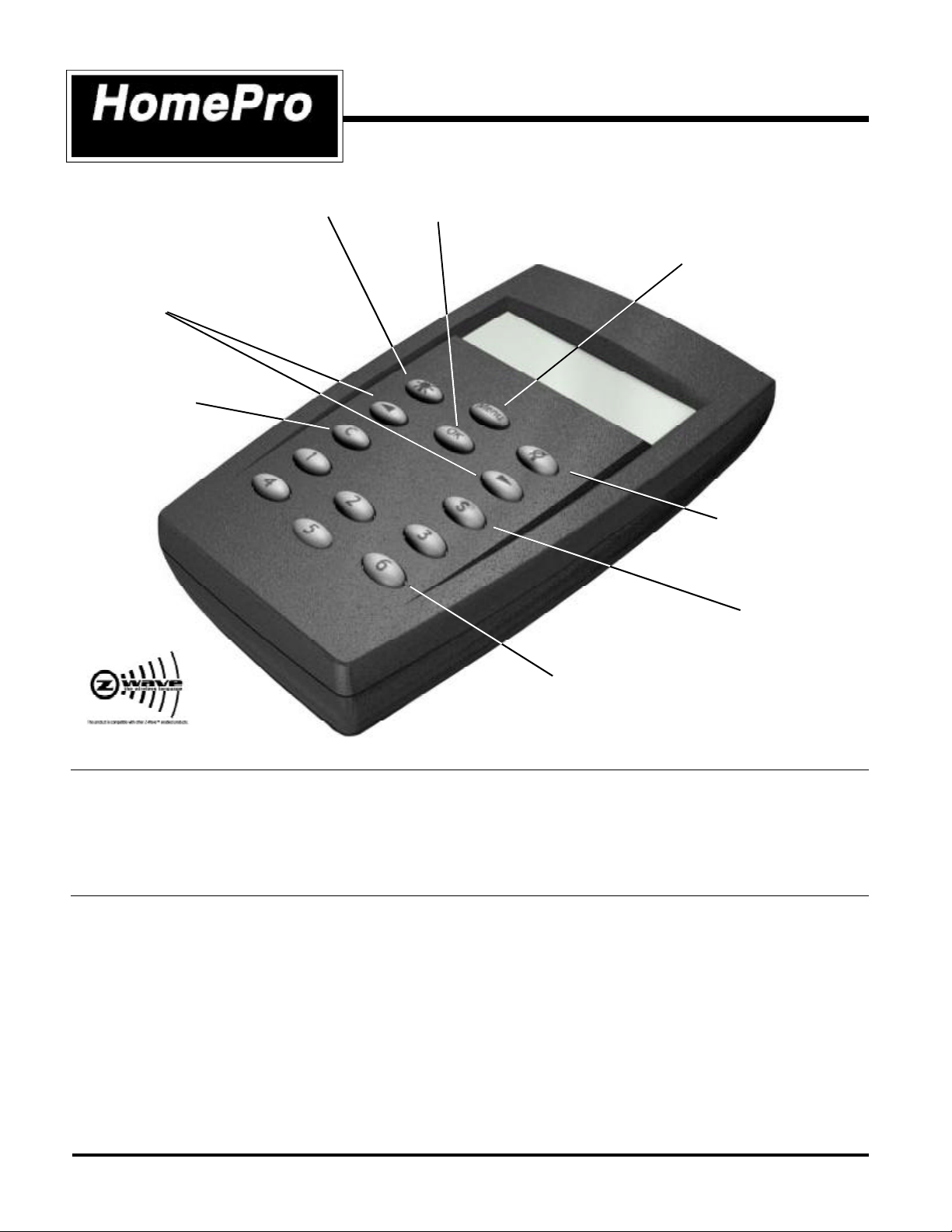
ALL ON Button
(Turns all included
modules ON)
Navigation Buttons
(Scroll left or right through menus)
Clear Button
(Cancels actions)
Radio Frequency Wireless Controller
OK Button
(Accepts selection)
Menu Button
(Activates menu display)
ALL OFF Button
(Turns all included
modules OFF)
Scene Button
(Brings up scene menu)
Numbered Speed Buttons
(Quick access to groups and scenes)
BEFORE YOU BEGIN...
READ ALL INSTRUCTIONS
Remove battery cover on rear of control. Install two (2) AA alkaline batteries (included).
There are no field repairable assemblies on this unit. For warranty and general product information visit our web site
at www.act-solutions.com. If service is needed, the unit must be returned where purchased.
BUTTON LAYOUT
MENU ...................................... ACTIVATES THE MENU DISPLAY.
OK ........................................... ACCEPTS CHOICES ON THE DISPLAY.
LIGHT BULB (SOLID) ............... ALL MODULES ON.
LIGHT BULB (w/ SLASH) ......... ALL MODULES OFF.
LEFT ARROW .......................... MENU NAVIGATION BUTTON, LEFT.
RIGHT ARROW ........................ MENU NAVIGATION BUTTON, RIGHT.
C ............................................. CLEAR. CANCELS ACTIONS.
S ............................................. SCENE BUTTON. TURNS SCENES ON/OFF (THESE ARE GROUPS OF
MODULES & DIM SETTINGS PREDETERMINED BY USER).
“1” TO “6” ............................... SPEED BUTTONS. QUICK ACCESS TO USER DEFINED GROUPS AND
SCENES.
ZTH100 Operating Instructions (Version 1.26)
033005
2
by ADVANCED CONTROL TECHNOLOGIES, INC.
HomePro
Page 3

The HomePro Z-Wave Lighting and Appliance Control System
gives you the following functionality.
RF Home Automation
WIRELESS CONTROLLER
This user manual is designed to guide
you through the setup and features of
the HomePro Z-Wave Lighting and
Appliance Control System. You will be
amazed at the possibilities for control.
You can easily enhance the comfort and
security of your home or office. You’ll
see how easy it is to quickly create a
totally customized system that can
remotely control lamps and appliances
without costly professional installation...a
system that any do-it-yourself person
can easily handle.
For example, with just one Wireless
Controller you can control up to 64
individual lamp units or wall switches!
You can control a single receiver, in
groups, or all receivers at once. You can
turn on custom programmed mood
lighting and use timers for lighting as a
burglar deterrent.
This user guide tells you how to create
your system. Instructions for installation
and setup of built-in components (wall
switches, dimmers, etc.) are included
with those components.
Safety and Security
n All OFF/ALL ON
On the way out you can turn off all lights in the house with one
button. At night, if you hear noises, you can turn all lights in the
house on from your bedroom.
n Timers
Let the clock control your lamps and appliances so they automatically turn on and off at preset hours. You won’t ever have to come
into a dark house again.
Comfort
n Remote Control
Control your lights wirelessly from the sofa, the bed, the kitchen or
wherever you are.
n Grouping
No more wandering from lamp to lamp. Control groups of lamps
simultaneously with one button.
n Scenes
Create and save custom lighting scenes for special occasions like
dinner parties, TV watching, romantic atmosphere, book reading, etc.
n Dimming
Dimming lights with the HomePro Control System saves on electric
bills.
n Thermostat Control
Switch from Heating to Cooling modes and adjust setpoint from
your easy chair.
Full Coverage plus added communication with Version 1.26
One of the key features of the HomePro Z-Wave is the fact that Z-Wave automatically routes the signal from one
device to the next, effectively going around obstacles and radio dead spots in your home or office. You only need to
be within 100 feet of any HomePro Z-Wave device to communicate with all other HomePro Z-Wave devices, so the
more HomePro Z-Wave enabled devices you have in your home or office, the better the coverage and the more
reliable the network becomes.
New software features (Version 1.26) allow changing the factory configuration of devices and reviewing the settings.
In addition it allows association of a device with other specific devices and a review of those associations. The
version of any HomePro ZTH100 can be verified by the following: Go to Setup Menu/Reset Remote Control/Factory
Default/press ALL LIGHTS OFF button.
The ZTH100 allows most devices into a group so they can be controlled by the remote. The device types that will
specifically not be added to a group (though they will be added to the Z-Wave system) are the following: Thermostat
Controller, Repeater Slave, Binary Sensor, Multilevel Sensor, Pulse Meter, Entry Control and Non Interoperable.
The types listed above will not be controlled by the remote because they either have nothing to control or do not support
the BASIC COMMAND which the remote uses to turn devices on and off. Device ID is shown when the device is added
to the network.
HomePro
by ADVANCED CONTROL TECHNOLOGIES, INC.
3
ZTH100 Operating Instructions (Version 1.26)
033005
Page 4
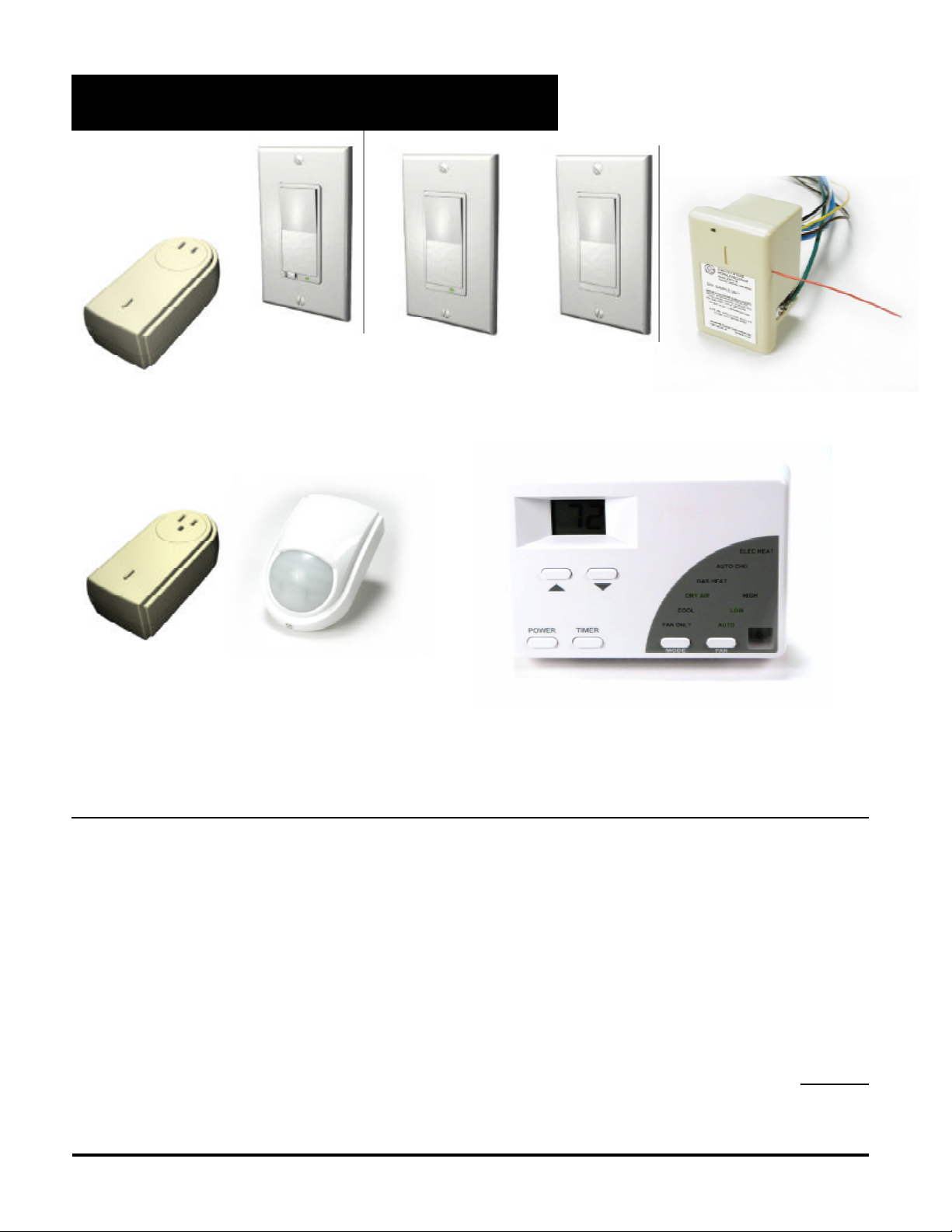
Introduction to HomePro Products
ZDW100 Wall
Dimmer
ZDW120 2-Wire
ZDP100
Plug-In Dimmer
Module
ZRP100
Plug-In Appliance
Module
This controller is designed to work with the HomePro products shown. Most other Z-Wave modules of other device classes can be added to
the system and will also act as repeaters if they support this functionality..
Wall Dimmer
ZDW103 3-Way
Wall Dimmer
ZIR000
PIR Occupancy &
Security Sensor
ZRW100
Wall Switch
ZRW103 3-Way
Wall Switch
ZTW100
Wall Transmitter
AS101 Auxiliary
Wall Switch
ZRF113 Fixture
Receiver
ZTT000
Wall Thermostat
SYSTEM DESCRIPTION
The HomePro product line from Advanced Control Technologies includes several products that are intended to work
together to provide convenient control of all of your home lighting and appliances. By using the ZTH100 Wireless
Controller, all of these HomePro devices are linked by a state of the art wireless communications network featuring
patented Z-Wave technology. This technology insures that the commands that you give through the Wireless
Controller are reliably communicated by radio frequency to the intended HomePro device.
The Wireless Controller operates up to 64 HomePro devices, which include both plug-in and wall mounted dimmers
and switches. The Wireless Controller finds a way to route your commands to the intended device through other
HomePro dimmers and switches. This is possible because each of these devices are designed to retransmit the
commands that are sent through them to adjacent devices that might otherwise be out of range of the Wireless
Controller. The Z-Wave system provides that a command can be routed if necessary through as many as four
different devices in route to the intended device.
Communication with devices employing Z-Wave technology is bidirectional. That is, when a command is sent from
a Wireless Controller, an acknowledgment is sent back to it by the affected devices to confirm that the command
was received (not necessarily that the load changed state). In the unusual situation in which a command is not
properly received, a message will appear on the Wireless Controller’s display to inform the User.
ZTH100 Operating Instructions (Version 1.26)
033005
4
by ADVANCED CONTROL TECHNOLOGIES, INC.
HomePro
Page 5

Table of Contents
1. INTRODUCTION PAGE
1.1 Getting Started................................................................................................................ 6
2. TIME
2.1 Setting the Time...................................................................................................................... 6
3. GENERAL OPERATION
3.1 Wireless Controller software features..................................................................................... 6
3.2 Power Down and Display Time-out......................................................................................... 6
4. HOW TO USE THE ZTH100 FEATURES
4.1 Menu navigation and selection ............................................................................................... 7
4.2 Groups/Scenes........................................................................................................................ 7
4.2.1 Add module to Group .............................................................................................................. 8
4.2.2 Add module to Scene. ............................................................................................................ 8
4.2.3 Exceeding module limit........................................................................................................... 9
4.2.4 Adding unsupported device types to the network................................................................... 9
4.2.5 Name a Group/Scene.............................................................................................................. 9
4.2.5.1 Character set........................................................................................................................... 9
4.2.6 Remove module from Group/Scene........................................................................................ 10
4.2.7 Delete Group/Scene................................................................................................................ 10
4.3 Timer ....................................................................................................................................... 11
4.3.1 Create/Edit a Timer ....................................................................................................... ......... 11
4.3.2 Delete Timer .......................................................................................................................... 13
4.4 Add Thermostat....................................................................................................................... 13
4.4.1 Requesting Data from Thermostat.......................................................................................... 13
4.4.2 Changing Thermostat Settings................................................................................................ 13
4.4.3 Thermostat Modes.................................................................................................................. 14
4.4.4 Thermostat Set Point................................................................................................................ 14
4.4.5 Fan Modes............................................................................................................................... 14
4.5 Removing Thermostat............................................................................................................. 15
4.6 Setup....................................................................................................................................... 15
4.6.1 Association............................................................................................................................... 15
4.6.1.1 Assign Route............................................................................................................................ 17
4.6.2 Config Unit Menu..................................................................................................................... 17
4.6.3 Display contrast ...................................................................................................................... 18
4.6.4 Setup All On/Off ..................................................................................................................... 18
4.6.5 Copy configuration to another Wireless Controller.............................................. .................. 19
4.6.5.1 Sending information to another Wireless Controller................................................................ 20
4.6.5.2 Receive information from Master Wireless Controller............................................................ 21
4.6.6 Resetting Modules (plug-in lamp, appliance and wall mount.................................................. 21
4.6.7 Reset Wireless Controller....................................................................................................... 22
5. OPERATION MODE
5.1 Operation display.................................................................................................................... 22
5.1.1 Secondary wireless controller indication................................................................................. 22
5.1.2 Scene indication...................................................................................................................... 22
5.1.3 Low battery indication.............................................................................................................. 23
5.2 Using operation mode............................................................................................................. 23
5.2.1 Controlling groups using speed buttons.................................................................................. 23
5.2.1.1 Pressing a speed button briefly. ............................................................................................. 23
5.2.1.2 Holding a speed button down.................................................................................................. 24
5.2.2 Controlling groups using navigation buttons............................................................................ 25
5.2.3 Controlling scenes .................................................................................................................. 25
5.2.4 All ON/All OFF ........................................................................................................................ 25
6. OTHER INFORMATION
Other Z-Wave devices and Warranty...................................................................................... 26
FCC and IC Notice ................................................................................................................. 26
HomePro
by ADVANCED CONTROL TECHNOLOGIES, INC.
5
ZTH100 Operating Instructions (Version 1.26)
033005
Page 6
1. INTRODUCTION
1.1 GETTING STARTED
Congratulations on your purchase of the ZTH100 and other HomePro components. This manual will guide
you in understanding the full capabilities of the HomePro System and operation of the Wireless Controller.
Remove battery cover of ZTH100 Controller and install two AA batteries noting the correct direction.
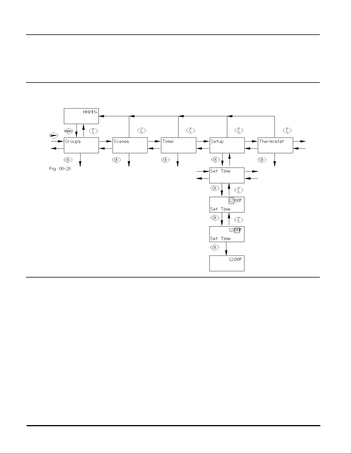
2. TIME
2.1 SETTING THE TIME
To set time, begin by pressing “MENU” button.
Note: Use arrow buttons to scroll though hours and minutes
3. GENERAL OPERATION
3.1 WIRELESS CONTROLLER SOFTWARE FEATURES.
• Provides user level control for 64 modules (i.e. one module, one group).
• Allows configuring of 64 groups.
• Eight (8) timers are available to the user. Each timer can be used to control any one of the existing groups.
• Displays the time in 12 hour AM/PM format.
• Allows multiple wireless controllers (one master and one or more secondary ones) in various locations for
convenience.
• Allows multiple Wireless Controllers “Each wireless controller comes pre-programmed from the factory with
a unique Home ID. This ID prevents unintended access to a user’s network of modules by neighbors or
others who may also be using HomePro products. If a user desires to add additional controllers to their
HomePro network however, there is a provision to allow this to be done without compromising this important feature (see section 4.6.5).”
3.2 POWER DOWN AND DISPLAY TIME-OUT
The ZTH100 goes into a power saving mode after a period of inactivity in order to conserve battery life.
Pressing any button will cause the unit to “wake up” and process any of your commands. The display is
blank in the power down mode.
ZTH100 Operating Instructions (Version 1.26)
033005
6
by ADVANCED CONTROL TECHNOLOGIES, INC.
HomePro
Page 7
4. HOW TO USE THE ZTH100 FEATURES
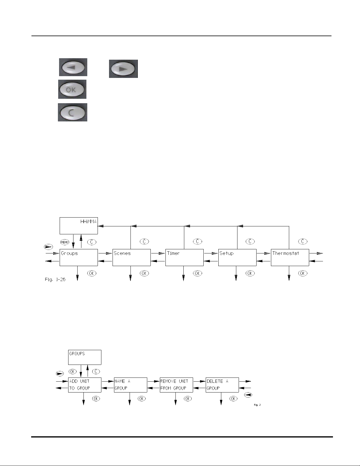
4.1 MENU NAVIGATION AND SELECTION
Pushing the “Menu” button will activate the menu display.:
a. and buttons are used to navigate through the menu. All menu levels wrap
around.
b. activates the currently selected menu item and recalls information from thermostat.
c. (or Clear) cancels the currently selected item and will in most instances step back to the
previously selected menu level. If used from top menu level the Controller will return to clock
display.
The top menu level behaves like this: Using the right and left arrow buttons you can toggle right or left through the
menu selections of : GROUPS
SCENES
TIMER
SETUP
THERMOSTAT
Top level menus wrap around, so arrow buttons in any direction will repeat menu selections. Push OK or C button
to activate display if asleep (blank).
Select any one by pressing OK. Follow instructions to set up that function (explained in following paragraphs). Using
the Clear button (C) at any time will take you back to the Time (which will auto-off after 5 seconds).
4.2 GROUPS/SCENES
The layout and behavior of the “groups” and “scenes” menus are very similar. Where they are identical, “groups” is
used as an example. Push OK or C button to activate display if asleep.
To select groups from 7 to 64 or scenes from 7 to 32 see page 28, section 5.5.2 and 5.2.3.
HomePro
by ADVANCED CONTROL TECHNOLOGIES, INC.
7
ZTH100 Operating Instructions (Version 1.26)
033005
Page 8
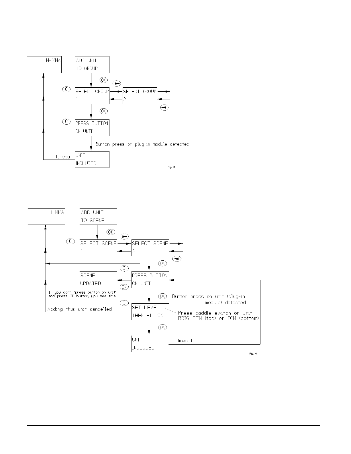
4.2.1 ADD MODULE TO GROUP
4.2.2 ADD MODULE TO SCENE.
Adding a module to a group using the menu is
done this way:
A group is a set of one or more modules that
are to be operated together as if they were
one device. More specifically, every module
that is included in a group will switch on or off
together as that group is turned on and off.
When a group is activated, each Lamp
Module in that group turns on, returning to its
last dim level – a level that in general, will
differ from module to module. Appliance
Modules may also be included in groups.
Alternatively if the group has been named, the
name shows up instead of the number. To add
more units repeat the procedure “ADD UNIT TO
GROUP”. Groups and scenes may each be
given user-defined names. See section 4.2.5 for
instructions on how to do this.
Adding a module to a scene is done this way:
Note: A Lamp or Appliance Module may be
included as a member of several different groups,
several different scenes, or several groups and
scenes.
Note: All of the properties of groups and scenes
also apply to HomePro wall dimmers and
switches.
A scene is a combination of one or more modules, except that the controller stores not only the combination,
but also the desired dim level for each Lamp Module. The dim level is stored at the time that a Lamp Module is
added to a scene. Consequently, when a scene is activated, the Lamp Modules will all go to their previously
defined dim levels regardless of what their most recent dim level may have been. Some modules may get
brighter while others may be pre-programmed by the user to become dimmer. Because Appliance and Wall
Switch Modules are switching devices, they will either be defined as on or off when added to a scene.
Note that hitting “C” will not clear units that have already been stored in the selected scene. A module is stored in
a scene when “UNIT INCLUDED” is shown in the display.
ZTH100 Operating Instructions (Version 1.26)
033005
8
by ADVANCED CONTROL TECHNOLOGIES, INC.
HomePro
Page 9
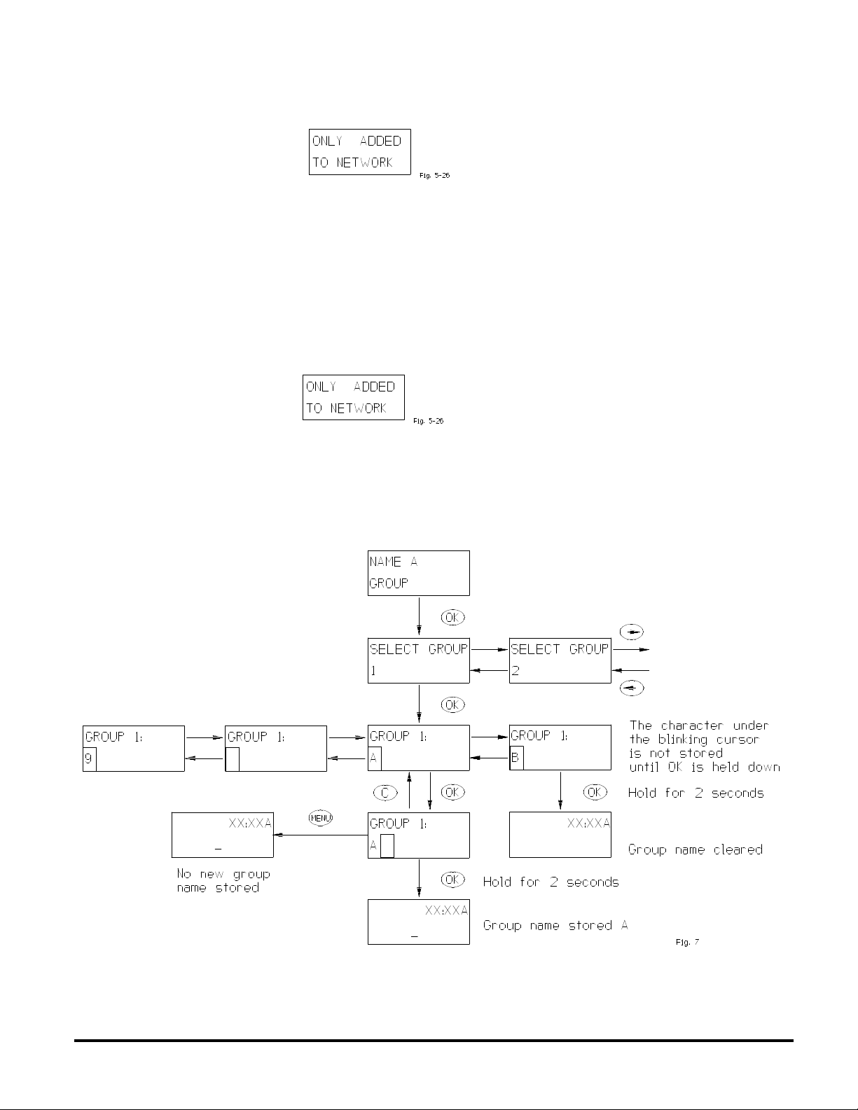
4.2.3 EXCEEDING MODULE LIMIT.
This ZTH100 Controller supports up to 64 modules. If the user tries to add more than 64 modules to a group or scene
this message will be displayed:
However the module will be given a valid ID and it will be used as a repeater if it supports this functionality, but it cannot
be directly controlled by this ZTH100 Wireless Controller. If a secondary Wireless Controller which handles more than
64 modules (could even be HomePro’s USB to RF controller) is set up using this Wireless Controller, then the module
will be made available for control in that secondary controller.
4.2.4 ADDING UNSUPPORTED DEVICE TYPES TO THE NETWORK
Devices of other types such as Remote Controller, Static Controller, Thermostat Controller, Repeater Slave, Binary
Sensor, Multilevel Sensor, Pulse Meter, Entry Control and Non Interoperable; they just cannot be controlled by this
ZTH100. If the user adds an unknown device to the network this information will be displayed:
4.2.5 NAME A GROUP/SCENE
To name a group or scene enter the relevant menu. Then select the group/scene name to be edited.
In order to delete a name, just select the group/scene and clear the old name using “C”.
Note: Outlined area indicates “blinking” cursor.
4.2.5.1 CHARACTER SET.
The characters available for naming are: ‘A’,’B’,’C’,’D’,..,’Z’, and ’0',’1',’2',..,’9',’ ‘
Note that no lower case letters are available to the user.
HomePro
by ADVANCED CONTROL TECHNOLOGIES, INC.
9
ZTH100 Operating Instructions (Version 1.26)
033005
Page 10

4.2.6 REMOVE MODULES FROM GROUP/SCENE.
Clear cancels the current selection. Navigation buttons only work if more than one group or scene exists.
4.2.7 DELETE GROUP/SCENE
Scroll left or right to find scene.
ZTH100 Operating Instructions (Version 1.26)
033005
10
by ADVANCED CONTROL TECHNOLOGIES, INC.
HomePro
Page 11

If no active groups or scenes exists the following occurs:
4.3 TIMER
The timer menu consists of the following menus:
Timer information is stored in the Wireless Controller – not in the module.
4.3.1 CREATE/EDIT A TIMER
There are eight timers available for the user. Each timer controls one of the existing groups as chosen by the user.
If an existing timer is selected that timer will be edited. Pressing the clear button will cancel the editing and leave the
timer as it was. The time indicated when selecting a timer is the start time of that timer.
HomePro
by ADVANCED CONTROL TECHNOLOGIES, INC.
11
ZTH100 Operating Instructions (Version 1.26)
033005
Page 12

Once a timer has been selected the following flow is executed when creating/editing a timer:
If a group is named the group name will be shown.
ZTH100 Operating Instructions (Version 1.26)
033005
12
by ADVANCED CONTROL TECHNOLOGIES, INC.
HomePro
Page 13

4.3.2 DELETE TIMER
When a timer is no longer needed it can be deleted using “Delete a timer” menu.
4.4 ADD THERMOSTAT
The ZTH100 will support only one (1) thermostat. If more than one (1) thermostat needs supported, then more
ZTH100’s will be required.
Scroll to the Setup Menu and Press OK.
Scroll to “Add Tstat To Network” and Press OK.
ZTH100 will prompt “Press Button On Unit”.
Once thermostat is added, the ZTH100 will show “Tstat Incl’d, with Support”.
This indicates that the thermostat was included into the Z-Wave network and that the ZTH100 was able to retrieve
the modes and set points the thermostat supports.
If the remote only shows “Thermostat Included” or “T’stat Incl’d, w/No Support” then the supported modes and
set points were not received from the thermostat and the ZTH100 will not allow the user to access all of the thermostat
functions. If this occurs, simply add the thermostat to the ZTH100 again until it shows “Tstat Incl’d with Support”.
4.4.1 REQUESTING DATA FROM THERMOSTAT
After the thermostat has been included into the ZTH100, repeatedly pressing the OK button will cause the ZTH100
to toggle between showing the actual temperature (if the thermostat supports sending actual temperature), current
mode and current set point of the mode, and fan mode (if the thermostat supports fan modes),
4.4.2 CHANGING THERMOSTAT SETTINGS
Scroll to Thermostat and Press OK.
You will see Thermostat Mode. At that point you could scroll left or right to change Set point or Fan Speed.
HomePro
by ADVANCED CONTROL TECHNOLOGIES, INC.
13
ZTH100 Operating Instructions (Version 1.26)
033005
Page 14

If instead you press OK, you will be directed to the thermostat modes of control (i.e.. Cooling, Heating, etc.).
In each case, the remote will retrieve the current setting of the thermostat and then allow you to change that setting
(depending on what is supported by the thermostat).
4.4.3 THERMOSTAT MODES
The ZTH100 supports HEAT MODE, COOL MODE, AUTO MODE, AUTO CHANGEOVER MODE, DRY AIR MODE,
FAN MODE ONLY, FURNACE MODE, MOIST AIR MODE. Scroll left or right to select. After you have changed the
setting, press OK.
If setting was recorded, display will say “Mode Successful”. If not it will say “Comm. Failed”, in which case reorient
the ZTH100 and try again.
4.4.4 THERMOSTAT SETPOINT
The ZTH100 supports sending set points from 55o F to 90o F and from 12o C to 32o C. Scroll left or right to select desired
set point.
The ZTH100 will display set points from 40o F to 90o F or from 4o C to 32o C. Above and Below those limits and the
ZTH100 will display > Max or < Min. After you have changed the setting, press OK. If setting was recorded, display
will say “Setpoint Successful”. If not it will say “Comm. Failed”, in which case reorient the ZTH100 and try again.
4.4.5 FAN MODES
The ZTH100 supports FAN MODE AUTO (high), FAN MODE ON (high), FAN MODE AUTO (low), FAN MODE ON
(low). Scroll left or right to select. After you have changed the setting, press OK.
ZTH100 Operating Instructions (Version 1.26)
033005
14
by ADVANCED CONTROL TECHNOLOGIES, INC.
HomePro
Page 15

4.5 REMOVING THERMOSTAT
To Remove Thermostat from Network, Scroll to Setup Menu, Choose “Reset Unit” and Press OK. (See Setup Menu
4.6).
4.6 SETUP
The setup menu is used to access system functions. The layout is as follows:
4.6.1 ASSOCIATION MENU
Allows you to associate other units to a module that supports this feature.
When you select “Associate Units” above, the following menu will appear:
ADD ASSOCIATION
Used when you want to associate one unit to another unit. The term associate means linking two units so that one unit
will send information to the other unit. The unit doing the sending is the source and the unit receiving the information
is the destination. If the modules are not within range of one another, refer to “Assign Route” below.
When you select Add Association, you will be prompted to select a group number as shown below:
This group number is the group within the source module in which the destination module will be placed when
associated. What each group is sent and does is solely dependent upon the source module. Refer to the instructions
that came with the source module.
Once the group number is selected (using the arrow buttons), press OK.
Now you will be prompted to “Press Button on Destin.”. This indicates you should now press the button on the
destination module. Refer to instructions of destination module on exactly what to do in this situation as you may have
to do more than simply pressing a button.
When the ZTH100 receives the destination module ID, it will then request you to “Press Button on Source”. Refer
to instructions of source module on exactly what to do in this situation as you may have to do more than simply pressing
a button.
After you have pressed the button on the source, the ZTH100 will either show “Successful” or “Comm. Failed”. If
the ZTH100 shows “Comm. Failed”, simply try again or move closer to the source module and try again.
HomePro
by ADVANCED CONTROL TECHNOLOGIES, INC.
15
ZTH100 Operating Instructions (Version 1.26)
033005
Page 16

REMOVE ASSOCIATION
Used when you want to remove an association in a unit . The unit in which the association is removed is the source
module and the unit being removed is the destination module. When you select “Remove Association”, you will be
prompted to select a group number.
What each group does is solely dependent upon the source module. What each group is sent is also dependent upon
source module. Refer to the instructions that came with the source module.
Once the group number is selected (using the arrow buttons), press OK.
Now you will be prompted to “Press button on Destin.”. This indicates you should now press button on the
destination module. Refer to instructions of destination module on exactly what to do in this situation as you may have
to do more than simply pressing a button.
When the ZTH100 receives the destination module ID, it will then request you “Press Button on Source”. Refer to
instructions of source module on exactly what to do in this situation as you may have to do more than simply pressing
a button. After you have pressed the button on the source module, the ZTH100 will either show “Successful” or
“Comm. Failed”. If the ZTH100 shows “Comm. Failed”, simply try again or move closer to source module and try
again.
REQUEST ASSOCIATION
If you desire to determine what modules a source module sends to, this function will allow you to determine that
information.
When you select “Request Association”, you will be prompted to select a group number.
This group number is the group within the source module in which the destination module will be placed in when
associated. What each group is sent and does is solely dependent upon the source module. Refer to the instructions
that came with the source module.
Once the group number is selected either using the arrow buttons, press OK.
Now you will be prompted to “Press Button on Unit” . Refer to instructions of module on exactly what to do in this
situation as you may have to do more than simply pressing a button.
When the ZTH100 receives the information from the unit, the ZTH100 will either show:
Use the arrows to show the units in the group.
Or it will show:
Which indicates the group is empty in the ZTH100.
Pressing the OK button at this point will also show you how many modules the group can support.
If the ZTH100 requests the association settings but does not receive information from the unit, the ZTH100 will simply
show “Request Sent” until the ZTH100 receives the information, goes to sleep, or you press the CLEAR button.
ZTH100 Operating Instructions (Version 1.26)
033005
16
by ADVANCED CONTROL TECHNOLOGIES, INC.
HomePro
Page 17

REQUEST TOTAL GROUPS
Although typically this information would be provided in the slave modules instructions, this function will allow you to
determine how many groups a device supports.
When you select “Request Total Groups”, you will be prompted to “Press Button On Unit” . Refer to instructions
of unit on exactly what to do in this situation as you may have to do more than simply pressing a button.
After you have done so, the ZTH100 will show:
where N is the number of groups in the ZTH100.
Also, if the ZTH100 requests the total groups a unit supports but does not receive information from the unit, the ZTH100
will simply show “Request Sent” until the ZTH100 receives the information, goes to sleep, or you press the CLEAR
button.
4.6.1.1 ASSIGN ROUTE
When two devices are not within range of one another, then a route can be assigned to the source module (the device
sending the information). This is dependent upon whether the source module is a normal slave or a routing slave. It
must be a routing slave (The routing slave can host a number of routes to communicate with a slave or controller but
the normal slave is typically a device that only receives input and reports status if polled). Again, the unit doing the
sending is the source module and the unit receiving the information is the destination module. Also of note, some
routing slaves only hold routes to one module, while newer routing slaves can hold routes to up to 5 modules. Refer
to instructions that came with device.
When you select “Assign Route”, you will be prompted to “Press Button On Destin.”. Refer to instructions of
destination module on exactly what to do in this situation as you may have to do more than simply pressing a button.
When the ZTH100 receives the destination module ID, you will be prompted to “Press Button On Source”. Refer
to instructions of source module on exactly what to do in this situation as you may have to do more than simply pressing
a button. After you have pressed the button on the source module, the ZTH100 will either show “Successful” or
“Comm. Failed”. If the ZTH100 shows “Comm. Failed”, simply try again or move closer to source module and try
again.
Note that units may still be unable to communicate to one another if there are no other modules that can communicate
to both the source and destination module.
DELETE ALL ROUTES
Removes all routes that were previously assigned to a routing slave.
When you select “Delete All Routes”, you will be prompted to “Press Button On Unit”. Refer to instructions of
module on exactly what to do in this situation as you may have to do more than simply pressing a button.
After pressing button, the ZTH100 will then show “All Successful” or “Comm. Failed”. If the ZTH100 shows
“Comm. Failed”, simply try again or move closer to module and try again.
4.6.2 CONFIG UNITS MENU
Allows you to send/receive configuration settings to a Z-Wave unit that supports such functionality.
When you select “Config Units” , the following menu will appear:
HomePro
by ADVANCED CONTROL TECHNOLOGIES, INC.
17
ZTH100 Operating Instructions (Version 1.26)
033005
Page 18

SET CONFIG
Allows you to set configuration settings to a unit that supports such functionality. When you select “Set Config”, you
will be prompted with
Consult the instructions that came with the unit you are configuring as to what each parameter number configures.
After selecting parameter number (use the arrow buttons to change parameter number, then press OK), you will
be prompted:
At this point, you will have to again consult the instructions for the unit you are configuring for information on how many
bytes the parameter being set contains. Then press the 1, 2, or 4 button accordingly. At this point you will be
prompted:
Use the arrow buttons to select value, then press OK.
If you have selected 2 or 4 bytes, when asked “# of Bytes”, you will be prompted for ConfigValue 2 and if necessary
ConfigValue3 and ConfigValue4.
After selecting the value(s) you will be prompted to “Press Button On Unit”. Refer to instructions of unit on exactly
what to do in this situation as you may have to do more than simply pressing a button.
After doing so, the ZTH100 will show “Successful” or “Comm. Failed”. If the ZTH100 shows “Comm. Failed”,
simply try again or move closer to unit and try again.
4.6.3 DISPLAY CONTRAST ADJUSTMENT
“C” cancels the contrast adjustment and returns to idle.
Default contrast is 50% which is restored whenever the batteries have been removed and reinstalled.
4.6.4 SETUP ALL ON/ALL OFF
Using this menu it is possible to customize the way ALL ON/ALL OFF works. Units can be included or
excluded from all on/off commands (refer to instructions of the devices you are controlling to determine if it supports
this feature).
ZTH100 Operating Instructions (Version 1.26)
033005
18
by ADVANCED CONTROL TECHNOLOGIES, INC.
HomePro
Page 19
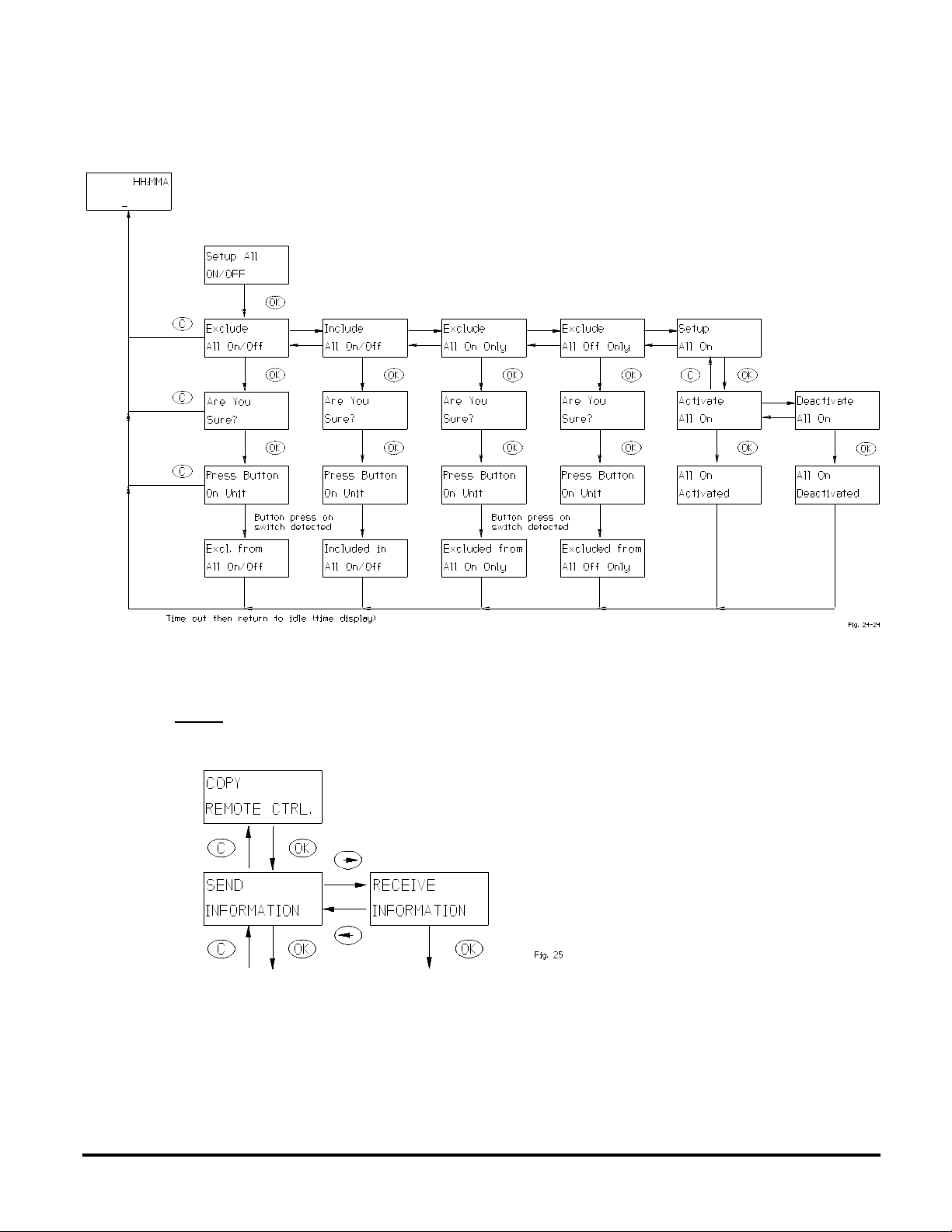
Setting a device to “Exclude All On Only” will cause the Z-Wave device to respond to All Off commands but not the
All On command.
Setting a device to “Exclude All Off Only” will cause the Z-Wave device to respond to All On commands but not the
All Off command.
4.6.5 COPY REMOTE CONTROL TO ANOTHER WIRELESS CONTROLLER.
This menu is used to copy information from the Master Wireless Controller to other controllers, so that they may
command modules known by the Master Wireless Controller.
Note: The master controller must be the controller used to include new modules to the network and to reset modules.
A replication of the master controller is done as follows:
1. Select “Receive information” on the controller which should receive the information (i.e. the Secondary
Wireless Controller)
2. Select “Send information” and either “Identical copy” or “Only system information” on the controller that is
to send the information (i.e. the Master Wireless Controller).
3. Wait until transmission is completed and both the wireless controllers return to clock display.
4. If a transmission error occur. Please repeat from Step 1.
HomePro
by ADVANCED CONTROL TECHNOLOGIES, INC.
19
ZTH100 Operating Instructions (Version 1.26)
033005
Page 20
Considerations:
1. It is important to note that all information on the receiving controller will be deleted before any information
is received.
2. Burglar deterrent and timer information is not copied to the secondary controller.
3. Slave Wireless Controllers cannot be used to add newly acquired or reset modules to the network.
4. If a secondary controller is added as one of the first 64 units, it will take up a module ID thus diminishing
the number of units by one that can be controlled from the master controller.
5. If modules are moved physically it should be done as mentioned in 4.6.5 and the replication should be
repeated.
6. New modules added to the network by the Master Wireless Controller are not automatically known by a
secondary wireless controller. They have to be transferred from the Master Controller by the replication
process.
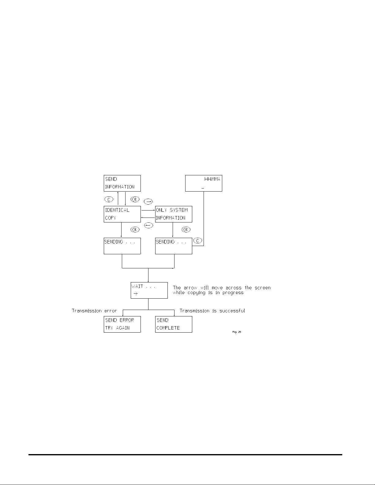
4.6.5.1 SEND INFORMATION TO ANOTHER WIRELESS CONTROLLER
There are two options. If the user wants an exact copy of the master controller including groups, scenes, names and
so forth, “Identical copy” should be selected. If the user wants to create groups, scenes and names from scratch “Only
system information” should be selected. When sending is activated the master controller will wait for a secondary
controller to respond to its module information broadcast.
ZTH100 Operating Instructions (Version 1.26)
033005
20
by ADVANCED CONTROL TECHNOLOGIES, INC.
HomePro
Page 21

4.6.5.2 RECEIVE INFORMATION FROM MASTER WIRELESS CONTROLLER
The flow of the “Receive information” menu is shown below.
4.6.6 RESETTING MODULES (INCLUDES PLUG IN LAMP, APPLIANCE AND WALL MOUNT)
If a module is to be moved to a new position or added to a new network, it has to be reset before doing so. This is
done using this menu.
HomePro
by ADVANCED CONTROL TECHNOLOGIES, INC.
21
ZTH100 Operating Instructions (Version 1.26)
033005
Page 22
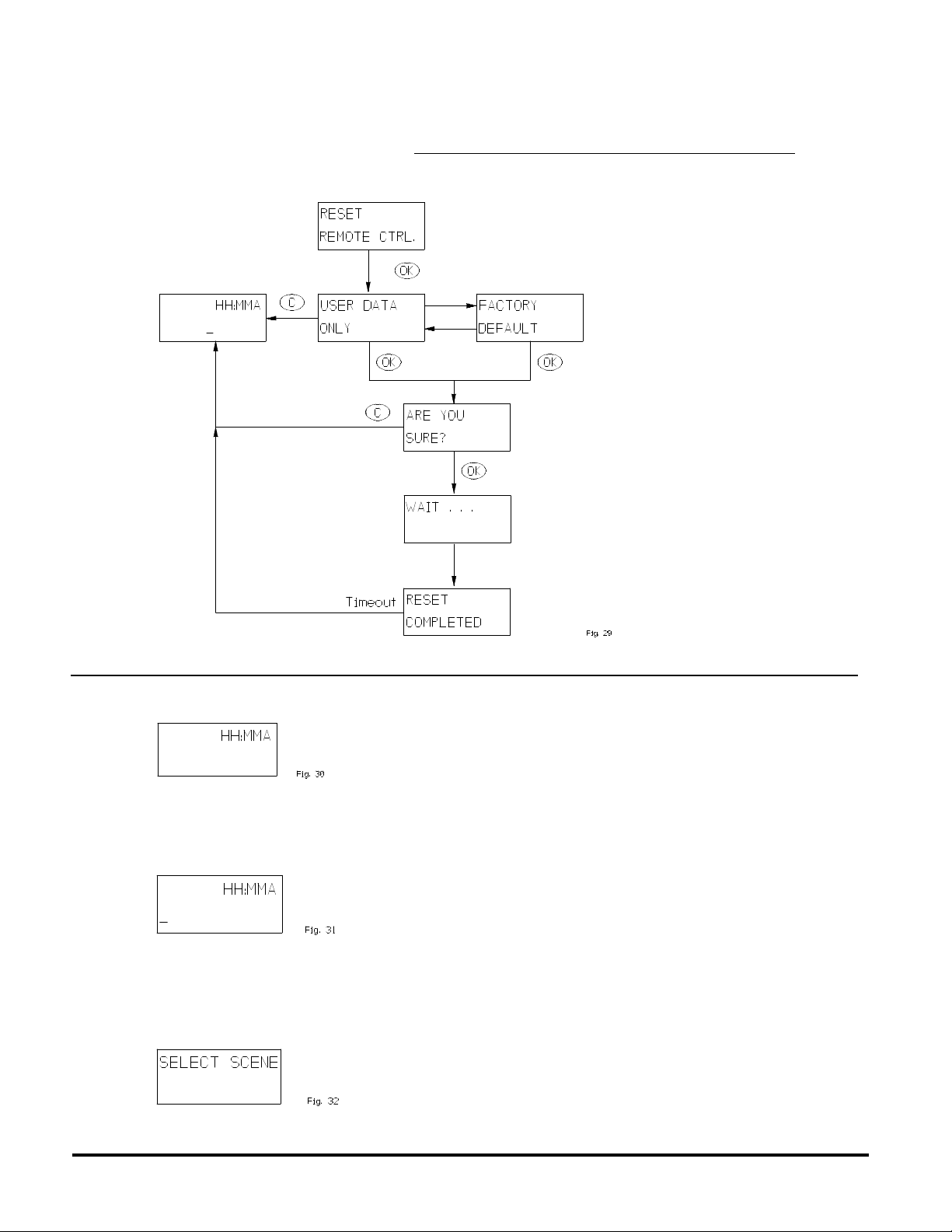
4.6.7 RESET WIRELESS CONTROLLER
The Wireless Controller can be reset in two different ways, by “user data only” selection or “factory default”. User
data only will only reset groups, scenes and names. The Wireless Controller will still retain information about the
modules that have been added to the network. A factory default reset should be used with extreme care. Factory
default will clear the controller of all information, and it will clear groups, scenes, names and will delete all modules
from the network.
5. OPERATION MODE
5.1 OPERATION DISPLAY
When the clock is displayed the Wireless Controller is in operation mode. It is from this mode the known modules
can be controlled through either groups or scenes.
5.1.1 SLAVE WIRELESS CONTROLLER INDICATION
When an underscore is shown in the left bottom corner the Wireless Controller, it is a secondary Controller with the
limitations as follows: Cannot reset unit and cannot add unit to network.
5.1.2 SCENE INDICATION.
From the operation mode press the scene prefix button “S”. The display will change to:
This indicates that the next button press (number pad) will be used to control a scene (if any available).
ZTH100 Operating Instructions (Version 1.26)
033005
22
by ADVANCED CONTROL TECHNOLOGIES, INC.
HomePro
Page 23
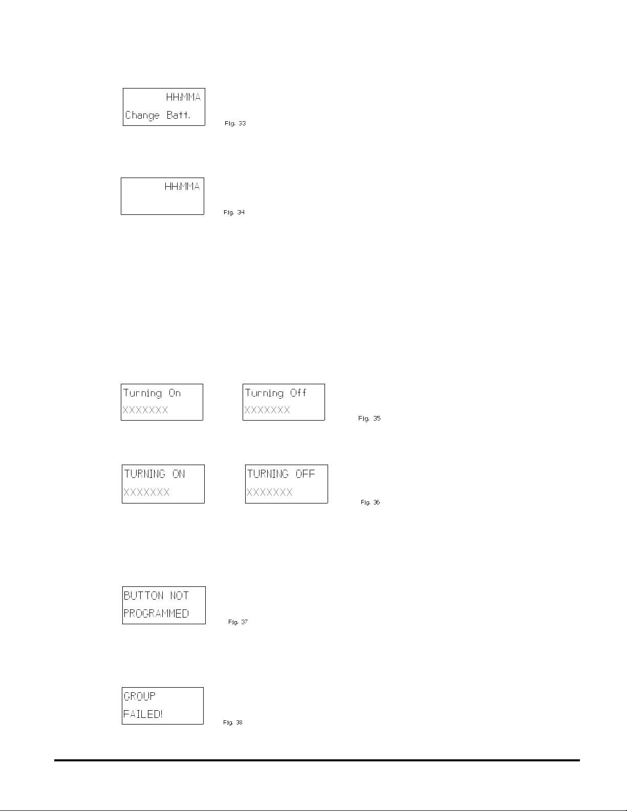
5.1.3 LOW BATTERY INDICATION.
This message indicates that it is time to replace the batteries. It will go away when the batteries have been replaced.
5.2 USING OPERATION MODE
Operation mode is the mode where the following display is indicated:
This mode is also the idle mode to which the Controller returns after performing operations. Push OK or C button to
activate display if asleep (blank). In this chapter the functions available in operation mode will be described.
5.2.1 CONTROLLING GROUPS USING SPEED BUTTONS.
Groups are controlled by either using the buttons 1 through 6 or by using the navigation buttons (‘<‘ or ‘>’) to select
the group that is to be controlled. Note that dimming a group never displays any failures that might have happened
during transmission as does an ON/OFF command.
5.2.1.1 PRESSING A SPEED BUTTON BRIEFLY.
The buttons marked 1 through 6 are used for speed access to the first 6 groups or scenes. Pressing the speed button
briefly will toggle the selected group on or off. Even if the Controller is powered down (display is off) a press on a speed
button will toggle the group. The display will show the following message:
Alternatively, if the group is named, the name will be displayed:
The text is displayed for a few seconds or until transmission is complete depending on which of these actions occurs
last.
If no group of the selected number is defined, the following message will be shown for a few seconds:
If for some reason the transmission fails, the following message will be shown until the user presses a button:
HomePro
by ADVANCED CONTROL TECHNOLOGIES, INC.
23
ZTH100 Operating Instructions (Version 1.26)
033005
Page 24
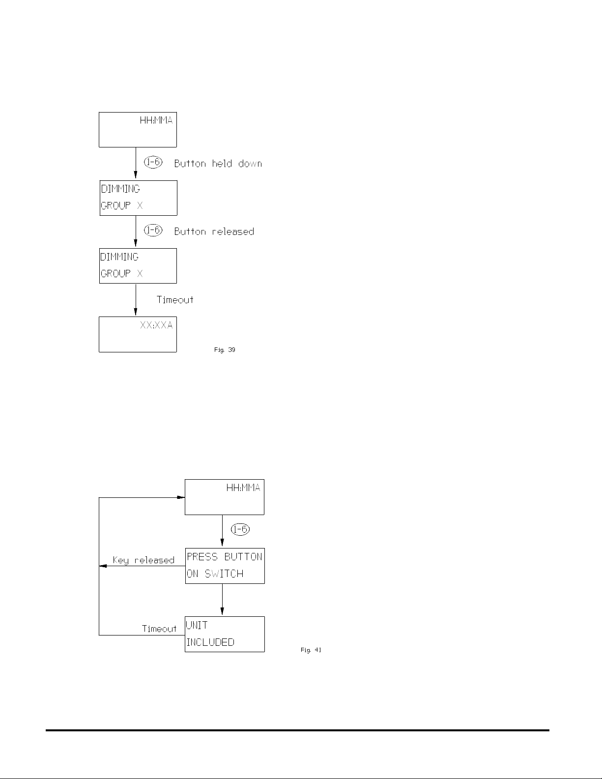
5.2.1.2 HOLDING A SPEED BUTTON DOWN.
Once a group is created on a speed button, it will start dimming when the speed button is held down.
This figure illustrates the display during dimming:
NOTE: If the group on the speed button is unused the user will be presented with the option to include a module
when holding down a speed button. This is done with the following display:
ZTH100 Operating Instructions (Version 1.26)
033005
24
by ADVANCED CONTROL TECHNOLOGIES, INC.
HomePro
Page 25
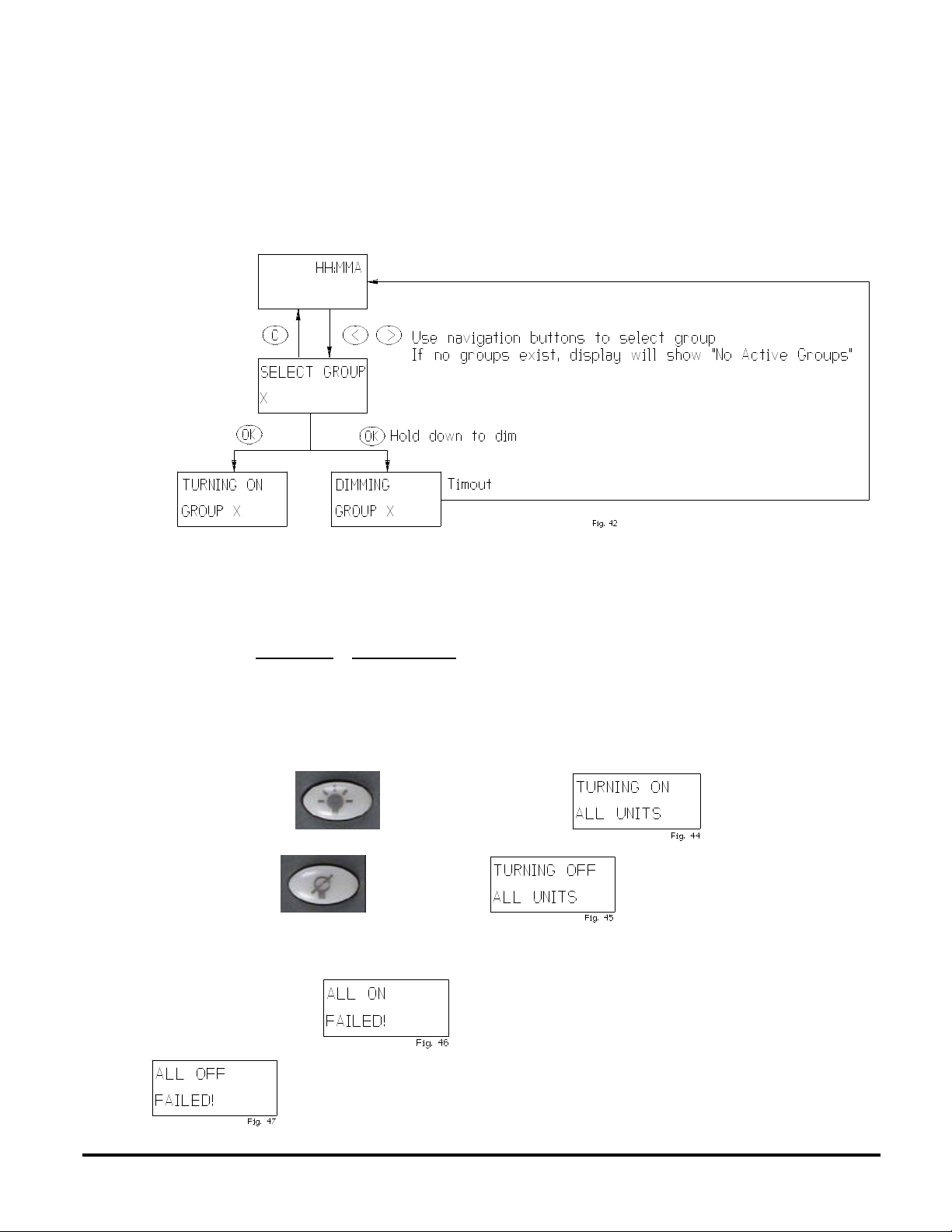
5.2.2 CONTROLLING GROUPS USING NAVIGATION BUTTONS.
Another way to access groups is to use the navigation buttons (“<“,”>”) from the operation state. This is the only way
to control the groups from 7 to 64. Also note that it is only existing groups that show up when the user toggles through
the list. If a group is named the name will be shown instead of the number. In order to switch a group ON or OFF the
“OK” button is pressed briefly. If the “OK” button is held down the group will be dimmed and it will be possible to add
module to the group being dimmed as mentioned in 5.2.1.2
It looks like this:
5.2.3 CONTROLLING SCENES
Scenes are accessed through the scene prefix button “S”. The Wireless Controller will indicate that it is in scene
selecting mode by the display shown in 5.1.2.
When in this mode the navigation or speed buttons can be used to select a scene. Once a scene has been activated
the Controller returns to group mode. Note that scenes can only be activated, not dimmed or deactivated. Unless
the modules in the scene are also controlled individually (i.e. they are also configured as a single module in a scene),
it is best to also set up an inverse scene of the same modules to turn them off taking advantage of the fact that scenes
can include switched off modules. Note that setting a scene will never return a failure message.
5.2.4 ALL ON/ALL OFF
Hitting “ALL ON” button will show this display
and “ALL OFF” button will result in
This display will be shown for the duration of the transmission, which for larger setups can be a while.
If the transmission fails either
or will be shown until the user presses a button (or times out after one minute).
HomePro
by ADVANCED CONTROL TECHNOLOGIES, INC.
25
ZTH100 Operating Instructions (Version 1.26)
033005
Page 26

6. OTHER INFORMATION
The Wireless Controller supports 64 HomePro modules. If the user adds Z-Wave devices other than HomePro to the
network, those modules will use one of the HomePro modules identification, if they are assigned as one of the first
64 modules.
However since the protocol supports up to 232 modules it is possible to create a setup with 64 HomePro modules
and numerous modules of other types. The HomePro modules must be added to the network before other types of
modules are included. The Controller application will ignore the modules that are added after the 64th, but the protocol
will make sure that they get a valid home/module identification and that they are used as repeaters if they support this
functionality.
WARRANTY
For warranty and general product information visit our web site at www.act-solutions.com
FCC NOTICE
Note: This equipment has been tested and found to comply with the limits for a Class B digital device, pursuant to part 15
of the FCC Rules. These limits are designed to provide reasonable protection against harmful interference in a residential
installation. This equipment generates, uses, and can radiate radio frequency energy and, if not installed and used in
accordance with the instructions may cause harmful interference to radio communications. However, there is no guarantee
that interference will not occur in a particular installation. If this equipment does cause harmful interference to radio or
television reception, which can be determined by turning the equipment off and on, the user is encouraged to try to correct
the interference by one or more of the following measures:
- Reorient or relocate the receiving antenna.
- Increase the separation between the equipment and receiver.
- Connect the equipment to an outlet on a circuit different from that to which the receiver is connected.
- Consult the dealer or an experienced radio/TV technician for help.
IC NOTICE
This Class B digital apparatus complies with Canadian ICES-003.
Cet appareil numérique de la classe B est conforme à la norme NMB-003 du Canada.
Operation is subject to the following two conditions: (1) this device may not cause interference, and (2) this device must
accept any interference, including interference that may cause undesired operation of the device.
Electrical
Power Two AA batteries
Signal 908.42 MHz
Range Up to 100 feet (line of sight between the Wireless Controller and the closest HomePro Plug-In
Lamp Module, Appliance Module, or Wall Switch).
ZTH100 Operating Instructions (Version 1.26)
033005
26
by ADVANCED CONTROL TECHNOLOGIES, INC.
HomePro
 Loading...