

Page 1
HomePro
RF Home Automation
Supplied with decorative
switch plate
Note: This module must be “Included in the
Network” only where it will be permanently
installed. The proper operation of this node in the
mesh network is dependent on it knowing its
location with respect to other nodes. You cannot
“test bench” configure this module.
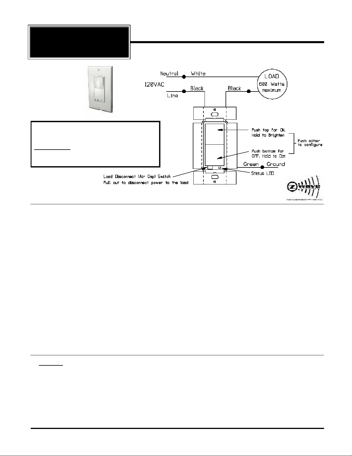
ZDW120 WALL MOUNTED DIMMER
Radio Frequency Controlled, 600W, 120 VAC, Two Wire Wall
ZDW120
Mounted Dimmer/Switch and Transceiver, Release 1.1
The ZDW120 Wall Mounted Dimmer is a component of the HomePro lighting control system. Wire the Wall
Mounted Dimmer in place of the standard wall switch according to the diagram above and program from the
Wireless Controller to operate loads. Inclusion of the ZDW120 Wall Mounted Dimmer on the ZTH100 Wireless
Controller menu allows remote ON/OFF control and dimming of lights connected.
This Wall Mounted Dimmer is designed to work with other Z-Wave enabled devices. Z-Wave nodes of other types
can be added to the system and will also act as repeaters if they support this function of repeating the signal
received to other modules in the system.
As part of a Z-Wave network, the ZDW120 will also act as a wireless repeater to insure that commands intended
for another device in the network are received. This is useful when the device would otherwise be out of the radio
range of the wireless controller.
There are no field repairable assemblies on this unit. If service is needed, the unit must be returned where
purchased.
CAUTION! Read and understand these instructions before installing. This device is intended for installation in
accordance with the National Electric code and local regulations in the United States, or the Canadian Electrical
Code and local regulations in Canada. It is recommended that a qualified electrician perform this installation.
To reduce the risk of overheating and possible damage to other equipment, do not install to control a
receptacle, a motor operated appliance, a fluorescent lighting fixture, or a transformer-supplied appliance, but
only permanently installed incandescent lamp fixtures. Make sure the lamp(s) to be controlled directly from this
dimmer total no more than 600 watts. Retain instructions for future use.
INSTALLATION
DANGER! - SHOCK HAZARD. Make all connections with the POWER OFF to avoid injury to the installer or damage
to the device.
1. Strip 3/4" of insulation from the ends of the conductors (if not already done) and make connections as shown in the Wiring Diagram. Note that the line side of the load must be switched.
2. Check connections to be sure they are tight and no bare conductors are exposed.
3. Make sure the load or installation does not exceed the device rating.
4. Install into a single gang (only) electrical wall box.
5. Restore the power.
HomePro
by ADVANCED CONTROL TECHNOLOGIES, INC.
0671-01
1
ZDW120 Instructions, Release 1.1
P/D 102406
Page 2

Wire this Wall Mounted Dimmer in place of an existing wall switch according to the diagram. See the ZTH100
Wireless Controller operating instructions to add this module under the command of the Wireless Controller.
Air Gap Switch
The ZDW120 has an air gap switch on the face (lower left), that when pulled out, completely removes the power
available to the load (more so than simply turning the dimmer off). This enables the lamps that are controlled by
the device to be changed with minimal danger of electrical shock. The air gap switch must be pushed all the way
back in for the dimmer to operate the lamps again.
BASIC OPERATION
Local Control
The ZDW120 allows the user to
• Turn ON or OFF, DIM or BRIGHTEN, the load attached.
• Include or exclude the module from the Z-Wave system
• Control other Z-Wave enabled devices.
Also, when a controller prompts you to “Send Node ID” or to “Press Button on Unit”, quickly tap on the top or bottom
of the paddle once to satisfy those instructions.
• Tapping top of the paddle turns the load attached ON.
• Tapping bottom of the paddle turns the load attached OFF.
• Pressing and holding the top of the paddle will brighten the load attached, and pressing and holding the bottom
of the paddle will dim the load. When OFF, pressing and holding the bottom of the paddle will cause the load
will go to the minimum dim level.
Note: Upon restoration of power after a power loss, the ZDW120 defaults OFF.
LED indication
The LED on the ZDW120 will turn on when the load attached is ON. However, the LED can be user configured
to turn ON when the load attached is OFF, if so desired, to act as a night light.
The ZDW120 will flicker its LED when it is transmitting to any of its 4 groups. This can be changed if desired.
ADVANCED OPERATION
All On/All Off
The ZDW120 supports the ALL ON/ ALL OFF commands.
The ZDW120 can be set to respond to ALL ON and ALL OFF commands 4 different ways.
Refer to your controller for information on how to set the ZDW120 to operate in the manner you desire. Some
controllers may be only able to set certain settings of ALL ON/ALL OFF response.
The 4 different ways the ZDW120 can be setup to respond to ALL ON and ALL OFF commands are:
• ZDW120 will not respond to ALL ON or the ALL OFF command.
• ZDW120 will respond to ALL OFF command but will not respond to ALL ON command.
• ZDW120 will respond to ALL ON command but will not respond to ALL OFF command.
• ZDW120 will respond to ALL ON and the ALL OFF command (default).
Association
The ZDW120 supports the Association command.
The ZDW120 can be set to control other Z-Wave devices. Those devices must be installed in their permanent
location. You can turn on and off, and even dim other Z-Wave devices once they are “associated” into 1 of 4 groups
within the ZDW120.
Each group is turned on or off (or dimmed) by tapping or holding the paddle a differing amount of times.
If you associate a Z-Wave device into Group 1, you can turn that device on and off by tapping the paddle on or
off once. The load attached to the ZDW120 will also turn on or off. Associating nodes into group 2 or 3 will cause
a very slight delay before the command is transmitted to group 1 nodes.
ZDW120 Instructions, Release 1.1
P/D 102406
0671-01
2
by ADVANCED CONTROL TECHNOLOGIES, INC.
HomePro
Page 3

You can brighten the controlled device by pushing and holding the top of the paddle, dim by pushing and holding
the bottom of the paddle.
If you associate a Z-Wave device into Group 2, you can turn that device on and off by tapping the top or bottom
of the paddle twice. You can brighten or dim devices by tapping the top or bottom of the paddle once and then hold
it down. The load attached to the ZDW120 is not affected.
If you associate a Z-Wave device into Group 3, you can turn that device on by tapping the top of the paddle three
times or off by tapping the bottom of the paddle three times. You can brighten devices by tapping the top of the
paddle twice or dim devices by tapping the bottom of the paddle twice and then hold it down. The load attached
to the ZDW120 is not affected.
Only associate transmitters or controllers into Group 4. Group 4 should be used only to update a transmitter or
controller on the status of the ZDW120 which might have been controlled from another device.
You can associate up to 5 Z-Wave devices into each of these four groups. For instructions on how to “associate”
a Z-Wave device into one of these groups, refer to your wireless controller instructions. (If you are using the
ZTH100 controller, refer to the Setup Menu, Association section).
A note about dimming, if you combine Z-Wave enabled dimmers and other types of Z-Wave devices in a group,
place a Z-Wave enabled dimmer into the empty group 1st to ensure that the dimming operates correctly.
Configuration
The ZDW120 supports the Configuration command.
The ZDW120 can be configured to operate slightly differently than how it works when you first install it. Using the
Configuration command you can configure the following:
You can use a ZTH100 to send Configuration commands. (Refer to the Setup Menu, Configuration section)
Set Ignore Start Level Bit When Transmitting Dim Commands
• Parameter No: 1
• Length: 1 Byte
• Valid Values = 0 or 1 (default 1)
The ZDW120 can send Dim commands to Z-Wave enabled dimmers. The Dim command has a start level
embedded in it. A dimmer receiving this command will start dimming from that start level. However, the command
also has a bit that indicates whether the dimmer should ignore the start level. If the bit is set to 1, the dimmer will
ignore the start level and instead start dimming from its current level. To clear this bit, configure this parameter
to the value of 0.
Suspend Group 4
• Parameter No: 2
• Length: 1 Byte
• Valid Values = 0 or 1 (default 0)
You may wish to disable transmitting commands to Z-Wave devices that are in Group 4 without “un-associating”
those devices from the group. Setting parameter 2 to the value of 1 will stop the ZDW120 from transmitting to
devices that are “associated” into Group 4.
It is possible that you may only want the units in Group 4 to track when the dimmer is being turned ON and OFF
and not when dimming.
Disable Group 4 During a Dim Command
• Parameter 13
• Length: 1 Byte
• Valid Values = 0 or 1 (default 0)
After the ZDW120 is commanded to stop dimming, it will then command the Z-Wave devices in Group 4 to the
ZDW120’s new level. To prevent the ZDW120 from commanding the Z-Wave devices in Group 4 during this
particular occurrence, set Parameter 13 to the value of 1.
Night Light
• Parameter No: 3
• Length: 1 Byte
• Valid Values = 0 or 1 (default 0)
HomePro
by ADVANCED CONTROL TECHNOLOGIES, INC.
0671-01
3
ZDW120 Instructions, Release 1.1
P/D 102406
Page 4

The LED on the ZDW120 will by default, turn ON when the load attached is turned ON. To make the LED turn ON
when the load attached is turned OFF instead, set parameter 3 to a value of 1.
Invert Switch
• Parameter No: 4
• Length: 1 Byte
• Valid Values = 0 or 1 (default 0)
To change the top of the paddle to OFF and the bottom of the paddle to ON, set parameter 4 to 1.
Ignore Start Level When Receiving Dim Commands
• Parameter No: 5
• Length: 1 Byte
• Valid Values = 0 or 1 (default 1)
The ZDW120 can be set to ignore the start level that is part of the dim command, regardless of whether the
command itself is telling the dimmer to ignore the start level or not ignore the start level embedded in the command
(see Parameter 1). Setting parameter 5 to a value of 0 will cause the ZDW120 to dim or brighten from the start
level embedded in the command.
Don’t Send Level Command After Transmitting Dim Commands
• Parameter 6
• Length: 1 Byte
• Valid Values = 0 or 1 (default 1)
When you press and hold the bottom of the ZDW120 paddle once, the Z-Wave devices that are associated into
Group 1 are sent the Dim command. After you release the paddle, the ZDW120 follows up by commanding the
devices to go to the same level of the ZDW120. By default, the ZDW120 is set not to do this. To enable ZDW120
to do this set this parameter to 0.
Adjusting Dim Rate
• Parameters 7-12
• Length: 1 Byte
• Valid Values: (See below)
There are 3 sets of parameters that can adjust the dimming rate of the ZDW120.
1. One set to control how fast the dim rate is when the dimmer receives a Z-Wave command,
excluding ALL ON or ALL OFF command (Parameter 7 and 8).
2. One set to control how fast the dim rate is when the dimmer is locally controlled (Parameter 9 and 10).
3. One set to control how fast the dim rate is when the dimmer receives an ALL ON or ALL OFF command
(Parameter 11 and 12).
These values can be changed instantly to allow various scenes and effects.
The first of these parameters is the “dim step” (dim rate) parameter. It can be set to a value of 1 to 99. This value
indicates how many levels the dimmer will change when the timer (discussed below) expires.
The second parameter is the timing (how fast the dim rate) parameter. It can be set to a value of 1 to 255.
This value indicates in 10 millisecond resolution, how often the dim level will change. For example, if you set this
parameter to 1, then every 10 mS the dim level will change. If you set it to 255, then every 2.55 seconds the dim
level will change.
With the combination of the two parameters that can control the dim rate, the dimmer can be adjusted to dim from
max to min or min to max at various speeds between 10 millisecond and 252.45 seconds (over 4.25 minutes).
On/Off Command dim rate (excluding ALL ON/ALL OFF commands)
Parameter 7 Dim step Parameter (default = 1)
Valid Values: 1-99
Parameter 8 Dim timer Parameter (default = 3)
Valid Values: 1-255
ZDW120 Instructions, Release 1.1
P/D 102406
0671-01
4
by ADVANCED CONTROL TECHNOLOGIES, INC.
HomePro
Page 5

Local Control dim rate
Parameter 9 Dim step Parameter (default = 1)
Valid Values: 1-99
Parameter 10 Dim timer Parameter (default = 3)
Valid Values: 1-255
ALL ON/ALL OFF dim rate
Parameter 11 Dim step Parameter (default = 1)
Valid Values: 1-99
Parameter 12 Dim timer Parameter (default = 3)
Valid Values: 1-255
The ZDW120 will flicker its LED when it is transmitting to any of its 4 groups. This flickering can be set to not
flicker at all (set to 0), to flicker the entire time it is transmitting (set to 1), or to flicker for only 1 second when it
begins transmitting (set to 2). By default, the ZDW120 is set to flicker for only 1 second.
LED Transmission Indication
• Parameter 19
• Length: 1 Byte
• Valid Values = 0 , 1, 2 (default 2)
Each Configuration Parameter can be set to its default setting by setting the default bit in the Configuration Set
command. See your controller’s instructions on how to do this (and if it supports it).
All Configuration commands will be reset to their default state when the ZDW120 is reset from the Z-Wave system.
SUC Support
There must be a Static Update Controller in your Z-Wave system for this feature to work. A Static Controller is
one that is not moved after addition to the network. The Static Controller can act as a gateway in the system, since
other nodes always know its position. The “always listening” advantage of the Static Controller is that other nodes
can transmit information frames to it whenever needed.
You can assign an “SUC Route” to the ZDW120. Refer to your Controller’s instructions on how to do this (if it
supports it). Assigning an SUC Route to the ZDW120 allows it to request an update of the Z-Wave devices that
are between it and the Z-Wave device to which it was trying to transmit. The ZDW120 will only request an update
when a transmission fails.
INTEROPERABILITY WITH Z-WAVE™ DEVICES
A Z-Wave™ network can integrate devices of various classes, and these devices can be made by different
manufacturers. The ZDW120 can be incorporated into existing Z-Wave™ networks.
The top or bottom of the paddle switch on the face of the ZDW120 can be used to carry out inclusion, association,
or exclusion.
WARRANTY
For warranty and general product information visit our web site at www.act-solutions.com
ABOUT ZDW120’S CERTIFICATION
This device complies with part 15 of the FCC Rules. Operation is subject to the following two conditions: (1) This device may
not cause harmful interference, and (2) This device must accept any interference received, including interference that may
cause undesired operation.
FCC NOTICE
Note: This equipment has been tested and found to comply with the limits for a Class B digital device, pursuant to part
15 of the FCC Rules. These limits are designed to provide reasonable protection against harmful interference in a
residential installation. This equipment generates, uses, and can radiate radio frequency energy and, if not installed
and used in accordance with the instructions may cause harmful interference to radio communications. However, there
is no guarantee that interference will not occur in a particular installation. If this equipment does cause harmful interference to radio or television reception, which can be determined by turning the equipment off and on, the user is encouraged to try to correct the interference by one or more of the following measures:
- Increase the separation between the equipment and receiver.
- Consult the dealer or an experienced radio/TV technician for help.
HomePro
by ADVANCED CONTROL TECHNOLOGIES, INC.
0671-01
5
ZDW120 Instructions, Release 1.1
P/D 102406
Page 6

IC NOTICE
This Class B digital apparatus complies with Canadian ICES-003.
Cet appareil numérique de la classe B est conforme à la norme NMB-003 du Canada.
Operation is subject to the following two conditions: (1) this device may not cause interference, and (2) this device
must accept any interference, including interference that may cause undesired operation of the device.
About ZDW120’s Certification
The ZDW120 has been thoroughly tested by the ETL SEMKO
division of Intertek, a nationally recognized testing laboratory. This
product was found to be in compliance with safety standards
ANSI/UL STD 1472 and CAN/CSA C22.2 No. 184.1.
In addition to compliance with product safety standards, the
ZDW120 is also certified to comply with applicable FCC and IC
rules and regulations governing RF and EMI emissions.
Power 120 VAC, 60 Hz.
Signal (Frequency) 908.42 MHz.
Minimum Load 40W, incandescent lamps only.
Maximum Load 600W, incandescent lamps only.
Range Up to 100 feet line of sight between the Wireless Controller and /or the closest
Operating Temperature Range 32-104O F (0-40O C). Indoor use only.
ZDW120 Instructions, Release 1.1
P/D 102406
HomePro Receiver Module.
0671-01
6
by ADVANCED CONTROL TECHNOLOGIES, INC.
HomePro
 Loading...