

Page 1
TH104
Powerline Carrier Control (PCC) 120 VAC,
Hotel Room Unitary HVAC Control
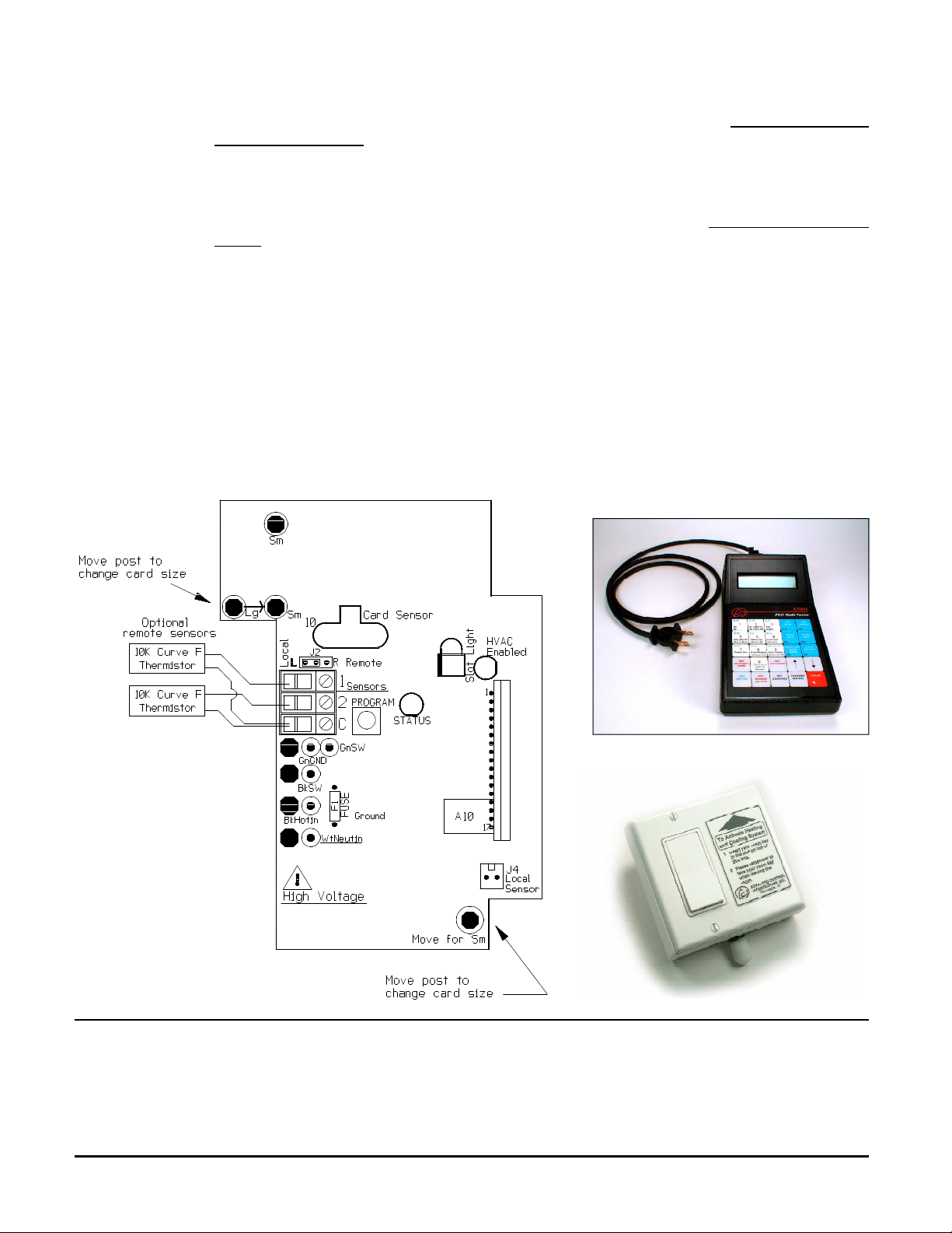
Unit is factory
set to accept a
large card. To
accept a small
card, move
snap-in posts
on printed
circuit board
from Lg &
"Move for Sm"
to both Sm
holes.
BEFORE YOU BEGIN...
READ ALL INSTRUCTIONS
Make sure your installation will conform to all applicable codes and requirements.
INSTALLATION
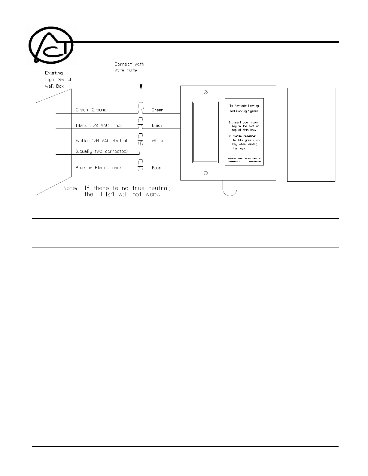
POWER CONNECTIONS:
WARNING: Make all connections with the power off to avoid injury to the installer or damage to
the device.
The WHITE and BLACK wires are the only required connections for powerline communications.
POWER LINE CONNECTIONS
The GREEN wire connects to the electrical system ground. The BLACK wire connects to the BLACK
(or hot) wire of the electrical system. The WHITE wire connects to the WHITE (or neutral) wire of
the electrical system. It must be a true neutral or the TH104 will not work. The BLUE wire connects
to the switched load. Make sure connections are tight and no bare conductors are exposed.
Leave cover off to enable address programming.
PROGRAMMING
Address Programming: Connect a suitable PCC transmitter such as the AT004 to the same power
line on which the TH104 is connected.
Select the desired letter & number code on the AT004 and press "Transmit" once. Press and hold
the PROGRAM push-button inside the TH104 for just over three seconds and release. The
TH104 STATUS LED should turn ON and remain on. The TH104 is now in PROGRAM mode.
Select the desired letter & number code again on the AT004 and push "Transmit" twice. The
TH104 STATUS LED should blink twice (indicating address setting received) and remain ON,
indicating it is still in program mode. If using a one way receiver, proceed to page 2 and read "Using
one-way receivers".
If a two way A10 receiver is being used, exit the PROGRAM mode by pressing the PROGRAM pushbutton on the TH104 once.
ADVANCED CONTROL TECHNOLOGIES, INC.
Indianapolis, Indiana 46278
0463-01
1
TH104 Installation Instructions
P/D 061208
Page 2
"Using one-way receivers" with the TH104: The TH104 default setting is to "request status" after
transmitting because it is designed to be used with A10 enhanced receivers having two way
communication. To use with receivers having only one way communication, you must disable the
status request feature as follows.
While still in PROGRAM mode transmit OFF on the AT004 twice. The TH104 STATUS LED will blink
three times indicating "request status" is set to OFF. To exit the PROGRAM mode press the
PROGRAM push-button on the TH104 once and the STATUS LED will go off, or 1 minute after the
last transmitted command it will automatically exit PROGRAM mode. LED indications are as
follows:
STATUS LED Off - TH104 is In RUN mode
STATUS LED On - TH104 In PROGRAM mode
STATUS LED blinks 2 times - Valid Address
STATUS LED blinks 3 times - Valid Command
STATUS LED blinks continuously - Hardware Error. Return for replacement
SLOT LIGHT and HVAC LED blink continuously, the following may be the problem:
1. Jumper J2 which selects Local (L) or Remote (R) sensor may not be correctly placed.
2. Remote sensor (thermistor) may be bad
3. Remote sensor wiring may be open or shorted.
4. Status Request failure. Incorrect status or no status is received.
5. Collision Failure (unable to transmit due to collision with other signals on powerline).
TH104 Internal
(Printed Circuit Board)
CHECK OPERATION
A typical installation will use an RI104 as a receiver to control the HVAC unit. To verify operation
program an RI104 to the same address as the TH104 and connect both the TH104 and RI104 to
same power line system. Manually turn off relay 1 of the RI104. Apply power to both devices and
insert a room key in to the TH104 slot. If both are operating properly, after a five second delay relay
1 on the RI104 should turn on. Remove the room key from the TH104 and relay 1 on the RI104
receiver will turn off after a 1 minute delay.
TH104 Installation Instructions
P/D 061208
0463-01
2
AT004
TH104
ADVANCED CONTROL TECHNOLOGIES, INC.
Indianapolis, Indiana 46278
Page 3

Typical Receiver
TEMPERATURE SENSORS
Control reverts to the TH104 temperature sensor only when the room key is removed. The TH104
then enables the HVAC if the room temperature falls to 60 degrees F (if HVAC unit is in heating
mode) or greater than 80 degrees F (if HVAC is in cooling mode), using internal or remote sensor.
The remote sensors are useful in multi-room suites were one room may get warmer or cooler than
the other. The TH104 is designed to accept any 10K curve F thermistor. Remote sensors are not
supplied with the TH104 and must be purchased by the installer if required.
The TH104 has two external sensor inputs and can be configured four different ways. Sensor 1 can
be selected for remote or local operation with Jumper Block J2.
1. Local Sensor only, J2 set to L (typical application, factory default)
2. One Remote Sensor only, J2 set to R (remote sensor wired to Sensor 1 terminal).
3. Local Sensor and One Remote Sensor, J2 set to L (remote sensor wired to Sensor 2 terminal).
4. Both Remote Sensors Only, J2 set to R (Remote sensors wired to Sensor terminals 1 and 2).
CHANGING ROOM KEY SIZES
The TH104 can accept two room key sizes. It is factory set to accept the large key card. To accept
the small key card, two snap in pegs on the printed circuit board must be removed from "Lg" and
"Move for Sm" hole positions & moved to both "Sm" hole positions.
LED INDICATOR LIGHTS
The three LEDs on the TH104 indicate following:
1. HVAC Enabled LED: With "Status Request" mode on, and key inserted, the TH104 transmits
ON and STATUS REQUEST after a 5 second delay, and the status LED lights and receiver
responds with a "STATUS ON".
With key removed the TH104 transmits OFF after a 1 minute delay, and the LED and receiver
turn off and receiver responds with a "STATUS OFF".
With "Status Request" mode off, and key inserted, the TH104 transmits ON after a 5 second
delay; the status LED lights and receiver comes on after completion of the signal transmission.
With key removed, TH104 transmits OFF after a one minute delay, LED and receiver goes off
upon completion of the signal transmission.
2. Status LED: Status LED is on only in the program mode and blinks after receiving a valid address
or configuration command. Status LED is off in the run mode.
3. Slot light LED: LED is on to illuminate key card slot. In case of error condition the Slot Light
LED will blink in unison with the HVAC Enabled LED (see below). If Slot Light LED and HVAC
Enabled LED are both blinking, any of the following may be the cause:
1. Jumper J2 which selects Local (L) or Remote (R) sensor may not be correctly placed.
2. Remote sensor (thermistor) may be bad.
3. Remote sensor wiring may be open or shorted.
4. Status Request failure (Incorrect status or no status is received).
5. Collision Failure (unable to transmit through other signals on the powerline).
Install cover.
There are no field repairable assemblies or user adjustments on this unit. It is covered by a two year
limited warranty. Should service be required, contact the distributor from which it was purchased.
RI104 Four
Relay Receiver
RI104 (without cover)
ADVANCED CONTROL TECHNOLOGIES, INC.
Indianapolis, Indiana 46278
0463-01
3
TH104 Installation Instructions
P/D 061208
 Loading...