

Page 1
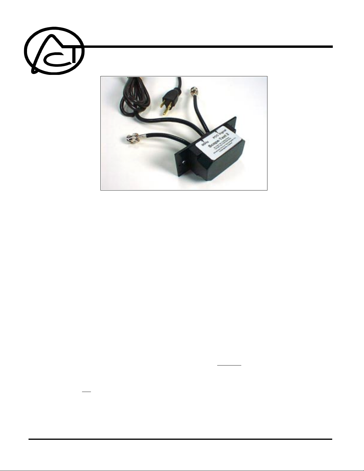
SCOPE-TEST2
Dual Channel PCC Oscilloscope Test Adapter
CAUTION! The “Scope-Test2” is a simple piece of test equipment for use by PCC (and X-10)
technicians as an aid in troubleshooting. The user assumes all responsibility for its safe use.
PURPOSE: The function of this device is to reduce the high voltage from an electrical
source (up to 277 volts AC) to approximately one twentieth its original voltage while also
allowing Powerline Control pulses to pass through to be viewed on a standard oscilloscope display.
OPERATION: Simply connect the BNC connectors to the inputs of a dual-trace
oscilloscope and adjust the oscilloscope’s controls according to its instruction manual.
Insert the male three prong plug into the electrical outlet from which the PCC signals are
to be tested. The 120kHz pulses generated by standard PCC transmitters and repeaters
will be displayed on the oscilloscope’s display. When properly adjusted, the 60Hz sine
wave will “trigger” the display and cause the 120kHz pulses to be simultaneously
displayed and will show how it is synchronized to that power distribution system. For
more information, please consult the ACT PCC Reference Manual, pages 73 through 75
(these pages are attached).
When used with a user-supplied, properly polarized, spring clip adaptor, the tester can be
used to check for the presence, amplitude and condition of PCC signal on Signal Carrying
Conductor (SCC) lines and on breaker panels.
Caution is urged when using this device
on any breaker panel!
The “Scope-Test2” is not intended for resale and is meant only for ESC use. This unit is
not covered by ACT’s usual 2 year warranty.
ADVANCED CONTROL TECHNOLOGIES, INC.
Indianapolis, Indiana 46278 (800) 886-2281
1
Scope-Test2
P/D 081399
Page 2
XII. BASIC TROUBLESHOOTING:
B. TEST EQUIPMENT:
NOTE: The examples that follow are representative of a standard, dual trace oscilloscope capable of adding the two inputs
together on its display. Simple sweep time and voltage variations will be offered but not complex oscilloscope
techniques. It is inappropriate to attempt to give a detailed accounting of oscilloscope use and techniques in this
manual. Because of the limited space available, this section will assume the technician has a basic understanding of, and experience with, fundamental oscilloscope operation.
One of the oldest and most versatile pieces of electrical test equipment is the oscilloscope. Basically, it is a device that
allows the technician to “see” what is on the electrical lines. The modern oscilloscope produces a visual representation
of the sampled voltage patterns using controls to adjust the range and timing of the graphical display.
The section on the “Theory of Operation”, pages 11 and 14 for example (PCC Reference Manual), hint at how a PCC signal
would appear on a properly adjusted dual trace oscilloscope. But to fully understand what the visual display represents,
some knowledge of voltage relationships needs to be understood.
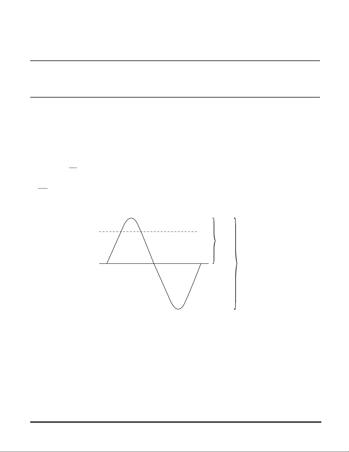
First, a typical 120/208v system is (obviously) described as having three phases, each with a voltage measured as 120
VAC, or 120 volts alternating current. What is understood, but not mentioned, is that 120 VAC is “RMS”, for “root-meansquare”. This is
(60Hz, United States standard, twice per cycle) and the actual voltage level changes micro-second by micro-second.
Therefore, 120 VAC is the “effective” value of the alternating voltage and would produce the same power as a continuous
(or non-alternating) voltage of that same value.
not the same as, but similar to, an average. Alternating current changes direction 120 times each second
120 VAC = 120 VAC RMS
= 169.68 V. PEAK
= 339.36 V. PEAK - PEAK
120V
169.68vp
339.36 vpp
Mathematically, the RMS value is calculated at 0.707 times the peak value. When the RMS value is known, the peak
voltage and the peak-to-peak voltage can be easily calculated (as shown in the above diagram).
This information has a direct bearing on the oscilloscope display. Instead of seeing a voltage waveform of 120v on the
O‘scope screen, the technician will see a sine wave which is over 339 volts from the top most crest to the bottom most
point. This can be very confusing for a first time oscilloscope user especially when trying to view a very small PCC signal,
which is often less than one 12,000th the size of the 339 volt, peak-to-peak, 60Hz sine wave.
Scope-Test2
P/D 081399
(Page 73, PCC Reference Manual)
2
ADVANCED CONTROL TECHNOLOGIES, INC.
Indianapolis, Indiana 46278 (8 00) 886-2281
Page 3

BASIC TROUBLESHOOTING:
B. TEST EQUIPMENT:
Low to moderately priced oscilloscopes have limited, but usually sufficient, capabilities. While some units have their
highest voltage scale of 5 volts/division (with 10 vertical divisions on the screen) others may have their highest scales as
10 or even 20 volts/division. With an oscilloscope having a 20v/division scale, it is easy to see that the highest voltage that
could be displayed would be 200vpp (volts, peak-to-peak).
A sine wave of 339vpp (120 VAC) could not be shown fully on the screen if it were not for the availability of special test probes
which enable the scope to measure much higher voltages. A test probe labeled “X10” (which has no connection with the
X-10 protocol) does not mean that it amplifies the test voltage ten times, quite the reverse, it reduces the test voltage by
a factor of 10, or 1/10th. Therefore a 339vpp sine wave would be displayed on the oscilloscope screen as just under 40vpp.
This reduced voltage is much easier and safer for the scope to handle.
The horizontal part of the oscilloscope allows for the unit to display events that occur in very small slices of time. Typically,
a moderately priced unit will have gradations of sweep time from as long as one half second per division (the point will take
5 seconds to traverse the screen, 10 divisions, at .5sec/div.) to as short as one tenth of a micro-second (.1m sec) per division
(the entire screen will display an event that occurs in the span of one millionth of a second).
Neither the slowest, nor the fastest sweep settings would be appropriate to view a single 60Hz sine wave. One cycle of
a 60Hz sine wave occurs in 16.66 ms (thousandths of a second). Setting the sweep time for 2ms/div. means the display
shows an event which is 20 milli-seconds in duration. That means that there is room for one full cycle, 16.66 ms, plus about
a quarter of the next cycle.
For most situations, this is
more than sufficient, however,
since most oscilloscopes have
both coarse and fine sweep
adjustments, they can be set
to show only one full cycle if
the technician desires. In order
to display a single cycle, the
oscilloscope sweep time can
be set for 1ms/div. and then
fine adjusted to show a single
sine wave.
5 volts/div.
About 40
volts peak
to peak
↵
Coarse setting = 1 ms/div, fine adjustment
to allow for one sine wave.
About 16.66 ms
ADVANCED CONTROL TECHNOLOGIES, INC.
Indianapolis, Indiana 46278 (8 00) 886-2281
(Page 74, PCC Reference Manual)
3
Scope-Test2
P/D 081399
Page 4

B. TEST EQUIPMENT:
In order to display a very small PCC signal (sometimes well below 25mv) while also showing a 339vpp, 60Hz sine wave,
a dual trace oscilloscope is recommended. The first trace, input “A”, is set to display one cycle as described on the previous
page, while the second trace, input “B”, is set to display only the bursts of 120kHz. To filter out the high voltage, 60Hz
power and only allow the small voltage 120kHz signal to pass through to the oscilloscope on input “B”, a CP000 (Passive
Coupler, 1:1 ratio) is recommended.
To
Line
X10 Probe
CP000
Sweep Time/div.
5v/div
A
B
1 ms.
}
.1v/div
}
The diagram above shows how the display would appear when viewed on a properly adjusted oscilloscope. The oscilloscope
sweep time is set to 1ms/division and fine adjusted to a time base that allows for only one sine wave. It also shows a 120v
sine wave which has been attenuated to 1/10th its original voltage by the scope probe and placed into channel “A”. The
vertical control for channel “A” is set to 5v/div.
Unlike the high voltage probe, the PCC signal is not reduced by the 1:1 probe and enters channel “B” which is set for .1v/
division. When the two traces are added together (“A+B”) it gives the technician an exaggerated view of the PCC signal
superimposed onto a greatly reduced 60Hz sine wave.
It would be awkward for any technician to attempt to do this type of field testing without having practiced in the safety and
unhurried comfort of one’s own test bench. For that reason, it is recommended that the technician explore testing and
troubleshooting under controlled conditions before having to do it in unfamiliar surroundings.
Many technicians find that building an oscilloscope “test box” (SCOPE TEST 2 also available from ACT) is not only an
excellent training aid but makes field troubleshooting easier. A basic diagram is shown below.
60 Hz ≈ 40 vpp
Black
White
Line
Neutral
CP000
Black
White
1 meg Ω
100 K Ω
100 Ω
PCC Signal
To
Scope
To
Scope
(Page 75, PCC Reference Manual)
Scope-Test2
P/D 081399
4
ADVANCED CONTROL TECHNOLOGIES, INC.
Indianapolis, Indiana 46278 (8 00) 886-2281
 Loading...