

Page 1
RI223
PCC 208/240 VAC Isolated Contact Module
BEFORE YOU BEGIN...
READ ALL INSTRUCTIONS
Make sure your installation will conform to all applicable codes and requirements.
TEST FOR SIGNAL STRENGTH AND NOISE...
using the AR300 and AT300. It is necessary to test the installation in the actual operating
environment. The amount and types of line loads may reduce the strength of the transmitted signal
and/or electrical noise may cause interference with the transmitted signal. Proper installation may
require additional couplers, filters or repeaters. Special coupling devices are required to allow signal
to be distributed to all phases and zero-crossings in multi-phase and multi-transformer distributions.
IF YOU HAVE ANY QUESTIONS...
Consult your nearest Engineered System Center (ESC) for additional information.
There are no field repairable assemblies on this unit. It is covered by a two year limited warranty.
If service is needed, the unit must be returned to the ESC where purchased. Contact your ESC for
return details.
ADVANCED CONTROL TECHNOLOGIES, INC.
Indianapolis, Indiana 46278
1
RI223 Installation Instructions
P/D 022597
Page 2
INSTALLATION
CHECKOUT
CAUTION! Make all connections with the POWER OFF to avoid injury to the installer or damage
to the device.
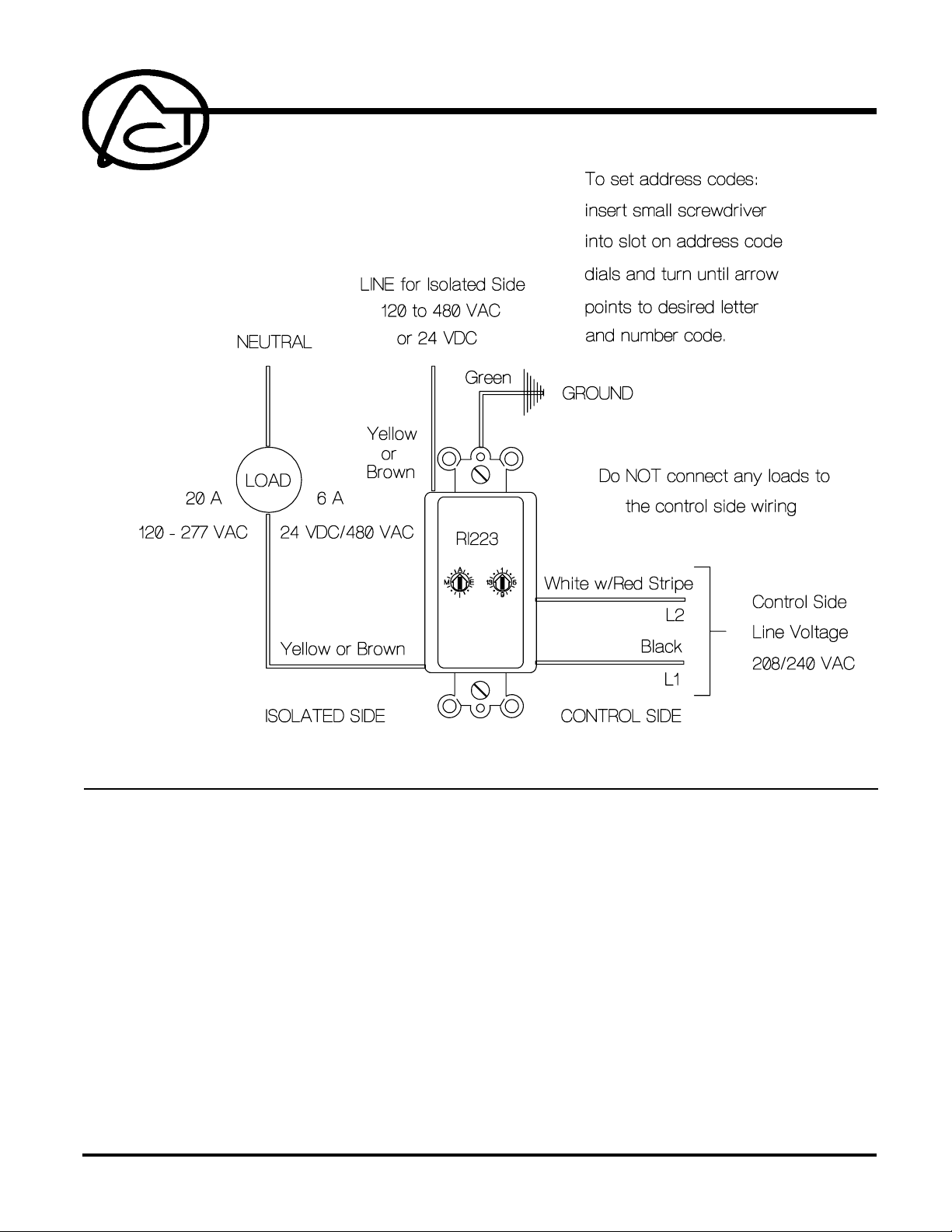
CAUTION! Do NOT apply voltages other than 208/240 VAC to the Control side. Do NOT use the
Control side to control a load.
1. Strip 3/4" of insulation from the ends of the conductors and make connections as shown in the
Wiring Diagram.
2. Check connections to be sure they are tight and no bare conductors are exposed.
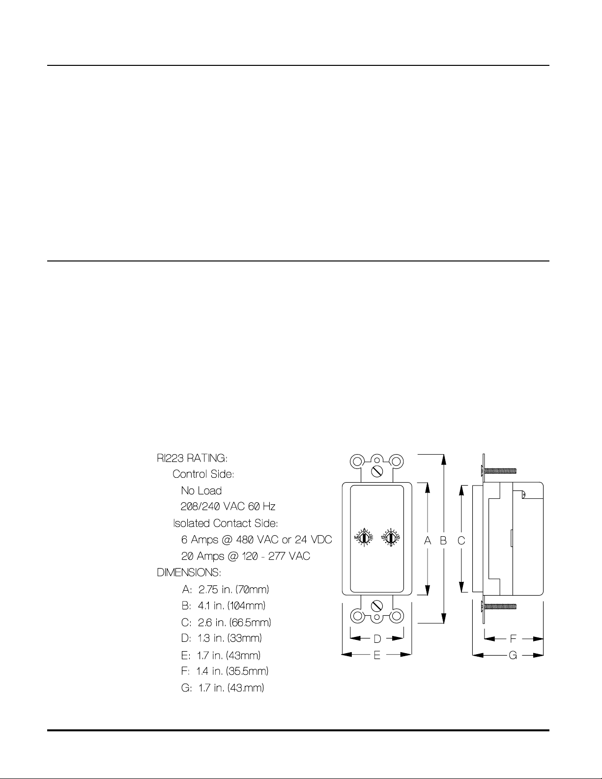
3. Make sure the load or installation does not exceed the device rating.
4. Install into a standard single or multi-gang electrical wall box. Use a deep box to avoid
interference with box fittings and allow room for wiring connections.
Mount the device in the wallbox and install the cover plate/trim ring (Decora
TM
or compatible style
available through electrical supply vendors).
1. Restore the power.
2. Set the address:
Up to 256 addresses can be selected from the device. The address consists of a Letter Code
(A through P) and a Number Code (1 through 16) for Unit address. Set the address code dials
as shown in the Wiring Diagram.
3. Test Remote Operation:
Using a controller, transmit “OFF”, “ON” and “ALL UNITS OFF” commands to ensure the device
turns the controlled load on and off in response to remote control (will not respond to "ALL
LIGHTS ON").
4. Test for Signal Strength and Noise once again using the AR300 and AT300.
RI223 Installation Instructions
P/D 022597
2
ADVANCED CONTROL TECHNOLOGIES, INC.
Indianapolis, Indiana 46278
 Loading...