

Page 1
RF300
PCC 277 VAC 5A Single Pole Fixture Module
BEFORE YOU BEGIN...
READ ALL INSTRUCTIONS
Make sure your installation will conform to all applicable codes and requirements.
TEST FOR SIGNAL STRENGTH AND NOISE...
using the appropriate test equipment. It is necessary to test the installation in the actual operating
environment. The amount and types of line loads may reduce the strength of the transmitted signal
and/or electrical noise may cause interference with the transmitted signal. Proper installation may
require additional couplers, filters or repeaters. Special coupling devices are required to allow signal
to be distributed to all phases and zero-crossings in multi-phase and multi-transformer distributions.
IF YOU HAVE ANY QUESTIONS...
Consult your nearest Engineered System Center (ESC) for additional information.
There are no field repairable assemblies on this unit. It is covered by a two year limited warranty.
If service is needed, the unit must be returned to the ESC where purchased. Contact your ESC for
return details.
INSTALLATION
CAUTION! Make all connections with the POWER OFF to avoid injury to the installer or damage
to the device.
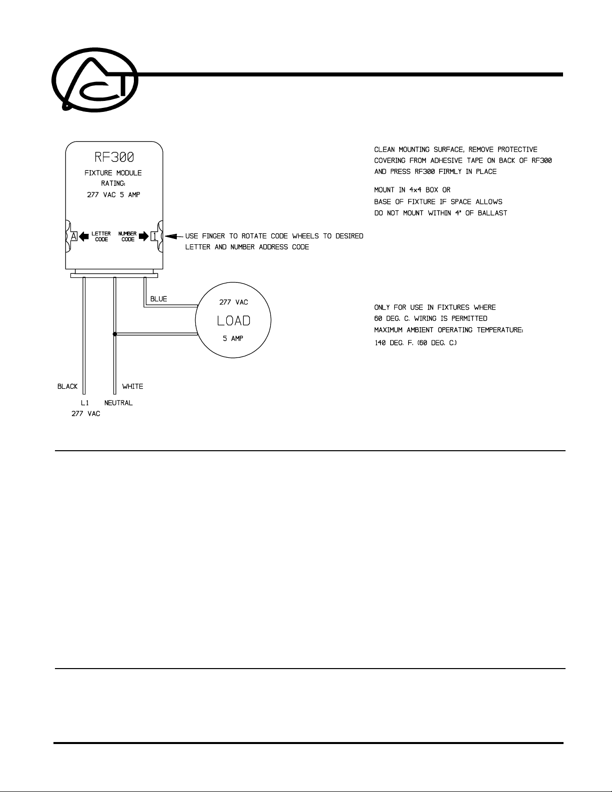
1. Strip 3/4" of insulation from the ends of the conductors and make connections as shown in the
ADVANCED CONTROL TECHNOLOGIES, INC.
Indianapolis, Indiana 46278
1
RF300 Installation Instructions
P/D 081399
Page 2
CHECKOUT
Wiring Diagram. The white lead (neutral) of the device does not have to be the neutral of the
load.
2. Check connections to be sure they are tight and no bare conductors are exposed.
3. Make sure the load or installation does not exceed the device rating.
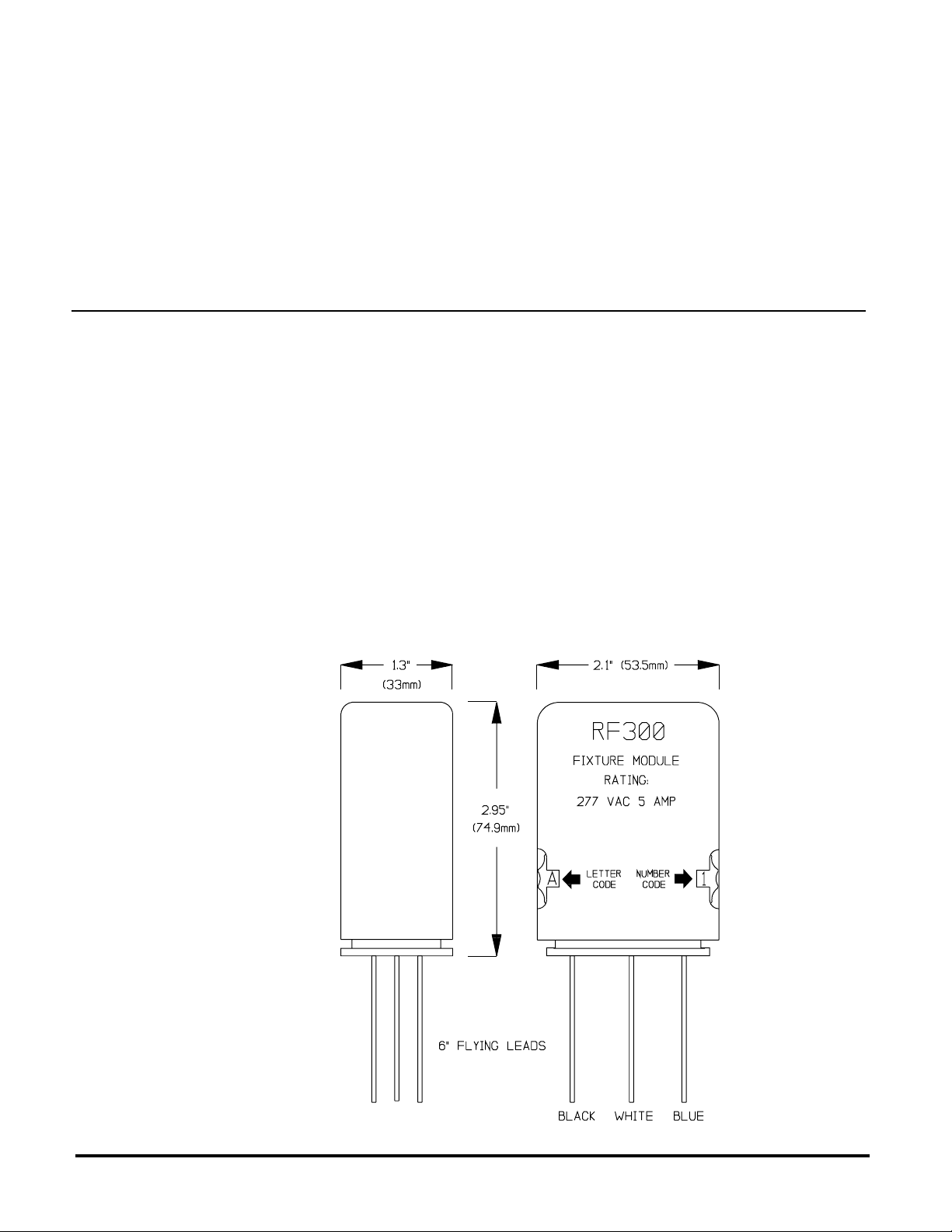
4. Install into any appropriately sized electrical box or the fixture itself. Clean the mounting surface,
remove the protective film from the adhesive tape and firmly press the module in place.
NOTE! Do not install within four inches of fluorescent ballast.
NOTE! Use only in fixtures where 60 degree C. wiring is permitted. Do not install in fixtures where
ambient temperature exceeds 140 degrees F. (60 degrees C.)
1. Restore the power.
2. Set the address:
Up to 256 addresses can be selected from this module. The address consists of a Letter Code
(A through P) and a Number Code (1 through 16) for Unit address. Set the address code dials
as shown in the Wiring Diagram.
3. Test Remote Operation:
Using a controller, transmit OFF, ON, ALL LIGHTS ON and ALL UNITS OFF commands
to ensure the module controls the load in response to remote control.
4. Test for Signal Strength and Noise once again using the appropriate test equipment.
RF300 Installation Instructions
P/D 081399
2
ADVANCED CONTROL TECHNOLOGIES, INC.
Indianapolis, Indiana 46278
 Loading...