

Page 1
BEFORE YOU BEGIN...
READ ALL INSTRUCTIONS
Make sure your installation will conform to all applicable codes and requirements.
TEST FOR SIGNAL STRENGTH AND NOISE...
using appropriate test equipment. It is necessary to test the installation in the actual operating
environment. The amount and types of line loads may reduce the strength of the transmitted signal
and/or electrical noise may cause interference with the transmitted signal. Proper installation may
require additional couplers, filters or repeaters. Special coupling devices are required to allow signal
to be distributed to all phases and zero-crossings in multi-phase and multi-transformer distributions.
IF YOU HAVE ANY QUESTIONS...
Consult your nearest Engineered System Center (ESC) for additional information.
There are no field repairable assemblies on this unit. If service is needed, the unit must be returned
to the ESC where purchased. Contact your ESC for return details.
INSTALLATION
RF234
A10 208/240VAC, 20A, Isolated Contact Relay Fixture Receiver,
Standard and Extended Addressing
CAUTION! Make all connections with the POWER OFF to avoid injury to the installer or damage to
the device. WARNING: SHOCK HAZARD. Do not use the manual ON/OFF switch on the RF to
disconnect the load for service. Signal can cause it to turn ON.
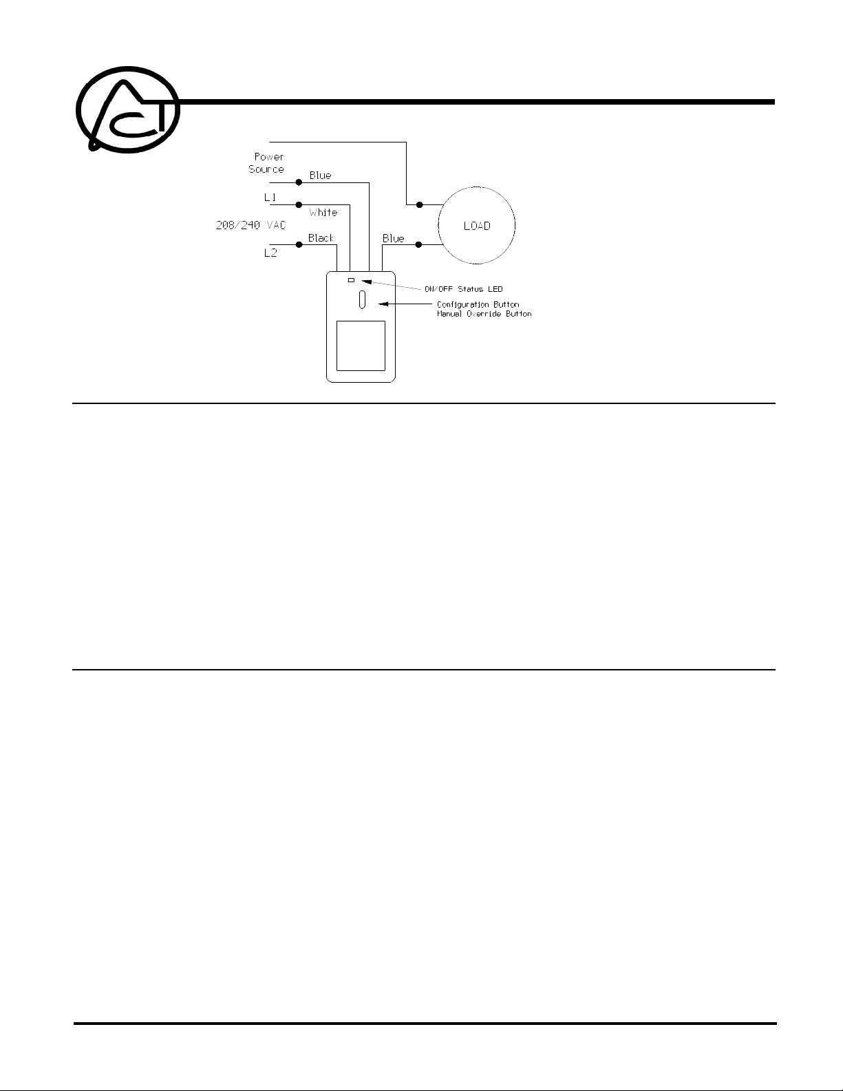
1. Strip 3/4" of insulation from the ends of the conductors and make connections as shown in the
Wiring Diagram. Connect L1 and L2 to the WHITE and BLACK flying leads. Connect the load
between a power source and the two BLUE wires. When the relay is turned ON, the LED
illuminates.
2. Check connections to be sure they are tight and no bare conductors are exposed.
3. Make sure the load or installation does not exceed the device rating.
4. Install into a 4" x 4" electrical box. Clean the mounting surface, remove the protective film from
the adhesive tape and firmly press the module in place.
NOTE! Do not install within four inches of fluorescent ballast.
The RF234 features two operating modes: Normal Mode and Configuration Mode. The Normal Mode
is the state in which the device performs its primary function. The Configuration Mode allows the user
to specify the address by which the device may be controlled, and allows the user to enable “All Lights
On, All Units Off, All Lights Off commands” (disabled when address is set) or disable “polite mode”
and enable “rude mode”.
ADVANCED CONTROL TECHNOLOGIES, INC.
Indianapolis, Indiana 46278
0693-01
1
RF234 Installation Instructions
P/D 071404
Page 2

OPERATION
CONFIGURING
CHECKOUT
If the RF234 address is configured to a standard code address:
The RF234 will respond to standard code On, Off, and Status Request commands.
The RF234 will respond with standard code Status On or Status Off commands when it
receives the standard code Status Request command.
If the RF234 address is configured to an extended code address:
The RF234 will respond to standard code On and Off commands addressed to the Letter
code and Unit code of its extended code address.
It will also respond to extended code On, Off, and Status Request commands.
The RF234 will respond with extended code Status On or Status Off commands when it
receives the extended code Status Request command.
To set the Address:
Press and hold the configuration button for 3 seconds. After 3 seconds, release the button. The
status led should be on steady. The RF234 can now be addressed.
Using a transmitter, transmit the desired address twice in succession. The transmissions must
be separated by at least six zero crossings (approximately 60mS, dependent on line frequency).
The RF234 will blink twice to indicate acceptance of desired address. The unit defaults to polite
when the address is configured.
Each time program mode is entered to change the configuration of the unit, your must first enter
the address of the unit before any feature is configured. Please have this address information
available.
If no address transmission is accepted by the RF124 while in program mode, and program mode
is exited, or the unit times out after one minute, the address of the unit as well as the features
previously programmed will remain active.
To enable “All Lights On, All Units Off, All Lights Off commands”:
To enable each command, transmit the command twice in succession (separated by at least six
zero crossings). The Status LED will blink 6 times when All Lights On is enabled, 8 times when
All Units Off is enabled, and 10 times when All Lights Off is enabled.
To disable “polite mode” and enable “rude mode”:
Transmit the configured address twice more in succession (separated by at least six zero
crossings). The Status LED will blink 4 times. If configuring this feature immediately after the
address is entered, only a single address transmission is required. The LED will still blink 4 times
to confirm entry.
To exit configuration mode:
To exit configuration mode, the configuration button can be pressed. The Status LED will indicate
the last known state. The RF234 will exit configuration mode and reenter normal mode after one
minute.
To check remote operation:
To check contact operation and Contact Status Transmission Manually:
RF234 Installation Instructions
P/D 071404
Using a transmitter, transmit the address and any configured commands to ensure the
module controls the load in response to remote control.
Test for signal strength and noise once again using AT004 or appropriate PCC test equipment.
Tap the program button once to close the contacts and to transmit the Status ON command.
The connected load will turn ON.
Tap the program button once again to open the contacts and to transmit the Status OFF
command. The connected load will turn OFF.
Ensure that the Status ON or OFF transmissions are accurate, and that the strength of these
signals are adequate, with the use of the AT004 test tool or other appropriate PCC test
0693-01
2
ADVANCED CONTROL TECHNOLOGIES, INC.
Indianapolis, Indiana 46278
Page 3
equipment.
TROUBLSHOOTING
If the LED continues to blink repeatedly, recycle power to the unit, and then reprogram the unit. If problem remains
after power-up and reprogramming, return the unit to the distributor where purchased and replace the unit.
WARRANTY
For warranty and general product information visit our web site at
www.act-solutions.com
ABOUT CERTIFICATION
This product has been thoroughly tested by the ETL SEMKO division of Intertek, a
nationally recognized testing laboratory. This product was found to be in compliance with
safety standards ANSI/UL STD 244A and CAN/CSA C22.2 No. 177.
Supply Voltage 208/240 VAC, +/-10%, 50 or 60 Hz
Power Consumption Less than 4.5W
Signal Input 120 KHz +/- 4 KHz, sensitive to 25 millivolts
ADVANCED CONTROL TECHNOLOGIES, INC.
Indianapolis, Indiana 46278
0693-01
Signal Output (Status) 5V peak to peak @ 5 ohms
Maximum switching capacity 20 Amps or 5000 VA
Maximum switching voltage 305 VAC
3
RF234 Installation Instructions
P/D 071404
 Loading...