

Page 1
RB104
A10 120/208 VAC, 30A, Box Mount Receiver,
Standard and Extended Addressing
BEFORE YOU BEGIN...
READ ALL INSTRUCTIONS
Make sure your installation will conform to all applicable codes and requirements.
INSTALLATION
POWER CONNECTIONS:
OUTPUT CONNECTIONS:
EXTERNAL SWITCH:
1. Warning, shock hazard: To service the load, disconnect main power. Do not use the
manual ON/OFF override switch to disconnect load for service.
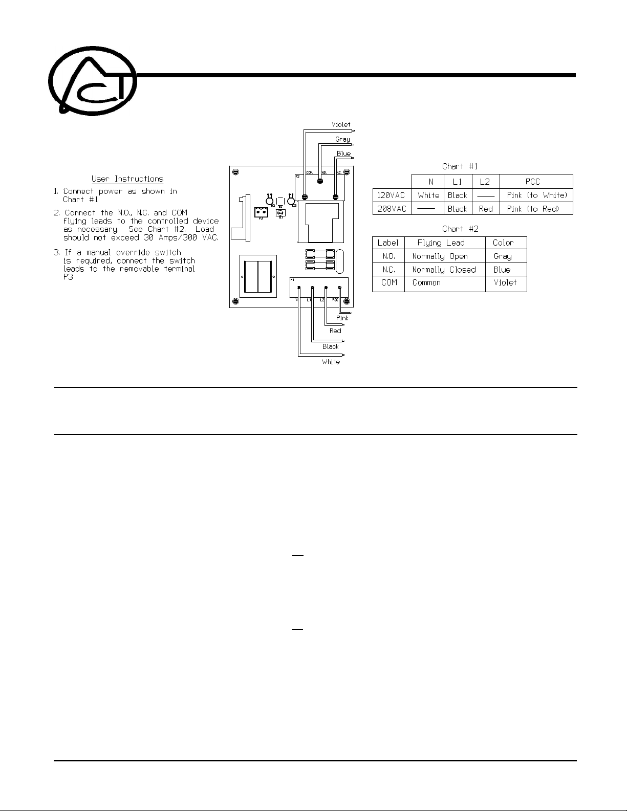
2. If single phase connection (120V) perform the following steps:
a) Connect the power supply neutral wire to the White wire marked “N” on the board.
b) Connect the line wire to the Black wire marked “L1” on the board.
c) Connect White wire “N” to Pink wire marked “PCC” on the board .
d) There should be no connection to the Red wire marked “L2” on the board.
3. If leg to leg connection (208V) perform the following steps:
a) Connect one line wire to the Black wire marked “L1” on the board.
b) Connect the second line wire to the Red wire marked “L2” on the board.
c) Connect Red wire “L2” to Pink wire marked “PCC” on the board.
d) There should be no connection to the White wire marked “N” on the board.
1. Connect the load to the GREY wire (normally open), or the BLUE wire (normally closed)
lead, and the VIOLET wire (common) lead.
2. See the "Relay Output" section in the specifications for maximum current and voltage
ratings.
1. Connect a switch to the removable terminal block P3. The switch may be any dry-contact
switch or relay. When the contact is closed the output relay will remain energized. When
the switch is opened the relay will default back to the last PCC command received.
ADVANCED CONTROL TECHNOLOGIES, INC.
Indianapolis, Indiana 46278
0571-02
1
RB104 Installation Instructions
P/D 012408
Page 2

OPERATION
2 The External Switch is only operational while the ON/OFF/AUTO switch is in the "AUTO”
position.
3. The External Switch is not required for proper operation of the unit - only use if this feature
is desired.
The RB104 features two operating modes: Normal Mode and Configuration Mode. The Normal
Mode is the state in which the device performs its primary function. The Configuration Mode allows
the user to specify the address by which the device may be controlled, and allows the user to enable
“All Lights On, All Units Off, All Lights Off commands” (disabled when address is set), disable “polite
mode” and enable “rude mode”, enable "power-up to last known state", and set the "time out"
feature.
If the RB104 address is configured to a standard code address…
The RB104 will respond to standard code On, Off, and Status Request commands.
The RB104 will respond with standard code Status On or Status Off commands when it
receives the standard code Status Request command.
If the RB104 address is factory configured to an extended code address or configured in the
field (see attached "Extended Code" Addendum for extended code instructions):
The RB104 will respond to standard code On and Off commands addressed to the Letter
code and Unit code of its extended code address.
It will also respond to extended code On, Off, and Status Request commands.
The RB104 will respond with extended code Status On or Status Off commands when it
receives the extended code Status Request command.
CONFIGURING
To set the address:
Press and hold the configuration button for 3 seconds. After 3 seconds, release the button. The
status LED should no longer be blinking and should be on steady. The RB104 can now be
addressed.
Using a transmitter, transmit the desired address twice in succession. The transmissions must
be separated by at least six zero crossings (50mS to 60mS, dependent on line frequency). The
RB104 will blink twice to indicate acceptance of desired address. The unit defaults to polite when
the address is configured.
To disable “polite mode” and enable “rude mode”:
Transmit the configured address twice more in succession (separated by at least six zero
crossings). The Status LED will blink 4 times.
To enable “All Lights On, All Units Off, All Lights Off commands”:
To enable each command, transmit the command twice in succession (separated by at least six
zero crossings). The Status LED will blink 6 times when All Lights On is enabled, 10 times when
All Units Off is enabled, and 8 times when All Lights Off is enabled.
To enable “Power Up to Last Known State”:
After the address has been configured, transmit a Standard Code ON command twice in
succession (separated by at least six zero crossings). The Status LED will blink 5 times to
indicate this feature has been enabled.
To exit configuration mode
To exit configuration mode, the configuration button can be pressed. The Status LED will resume
blinking. The RB104 will exit configuration mode and reenter run mode after one minute of no
activity.
RB104 Installation Instructions
P/D 012408
0571-02
2
ADVANCED CONTROL TECHNOLOGIES, INC.
Indianapolis, Indiana 46278
Page 3

CHECKOUT
Setting the time-out feature
Default state
First place the RB104 in run mode , then press the configuration button 3 times rapidly. After
releasing the button after the third press, the Status LED will stay on. This indicates RB104
is in time-out configuration mode.
Transmit the desired default state (Standard Code ON or OFF) twice in succession
(separated by six zero crossings) Note: the transmitter must be set to the same letter code
as the configured address.
The Status LED will blink 8 times if configured to default to OFF.
The Status LED will blink 7 times if configured to default to ON.
Default Time-out (Optional Feature)
After the default state is configured, the time-out time can be configured.
Transmit the desired time-out by transmitting a number code to the RB104 twice.
Number code 1 for example, will configure the unit to default to its default state after 1 hour.
Number code 2, will configure the unit to default to default to its default state after two hours.
And so on. The unit can be configured to default from 1 to 16 hours.
When the time-out period has been accepted the Status LED will flash 1 time and then
resume to being continuously on.
To exit time-out configuration mode, the configuration button can be pressed. The Status
LED will resume blinking. The RB104 will exit time-out configuration mode and reenter run
mode after one minute of no activity.
1. Test Operation:
Using a controller, transmit appropriate commands to ensure proper operation and
interference filtering. This product is compatible with standard X10 systems.
2. If at any time the STATUS LED flashes off and on quickly without stopping, reset the RB104
by powering the unit down and back up. If the error returns and cannot be cleared through
a reset, the unit could need repair or replacement.
Supply Voltage: 120/208 VAC, +/-10%, 50 or 60 Hz
Power Consumption: Less than 4.5W
Powerline Carrier Signal Input: X10 Powerline Carrier, sensitive to 50 millivolts
Signal Output (Status): X10 Powerline Carrier, 6V peak to peak @ 5 ohms
Maximum switching capacity: Resistive: 30A, 277 VAC - N.C. or N.O. contacts
Fuses (control circuit only): Two (2) 5 x 20mm time lag fuses rated 0.5A, 250V, user replaceable (Littlefuse 239,500 or Buss GDC-500mA).
ADVANCED CONTROL TECHNOLOGIES, INC.
Indianapolis, Indiana 46278
Motor: 1 H.P., 120 VAC or 1.5 H.P. 200 -600 VAC - N.C. or N.O. contacts
Ballast: 120 VAC, 10A - N.C. contact or 30A - N.O. /277 VAC, 10A - N.C. contact or 20A - N.O.
Tungsten 2A, 120 VAC - N.C. contact or 10A, 120 VAC - N.O. contact
Resistive DC: 30A, 28 VDC, - N.C. or N. O. contacts
0571-02
3
RB104 Installation Instructions
P/D 012408
 Loading...