

Page 1
CP000
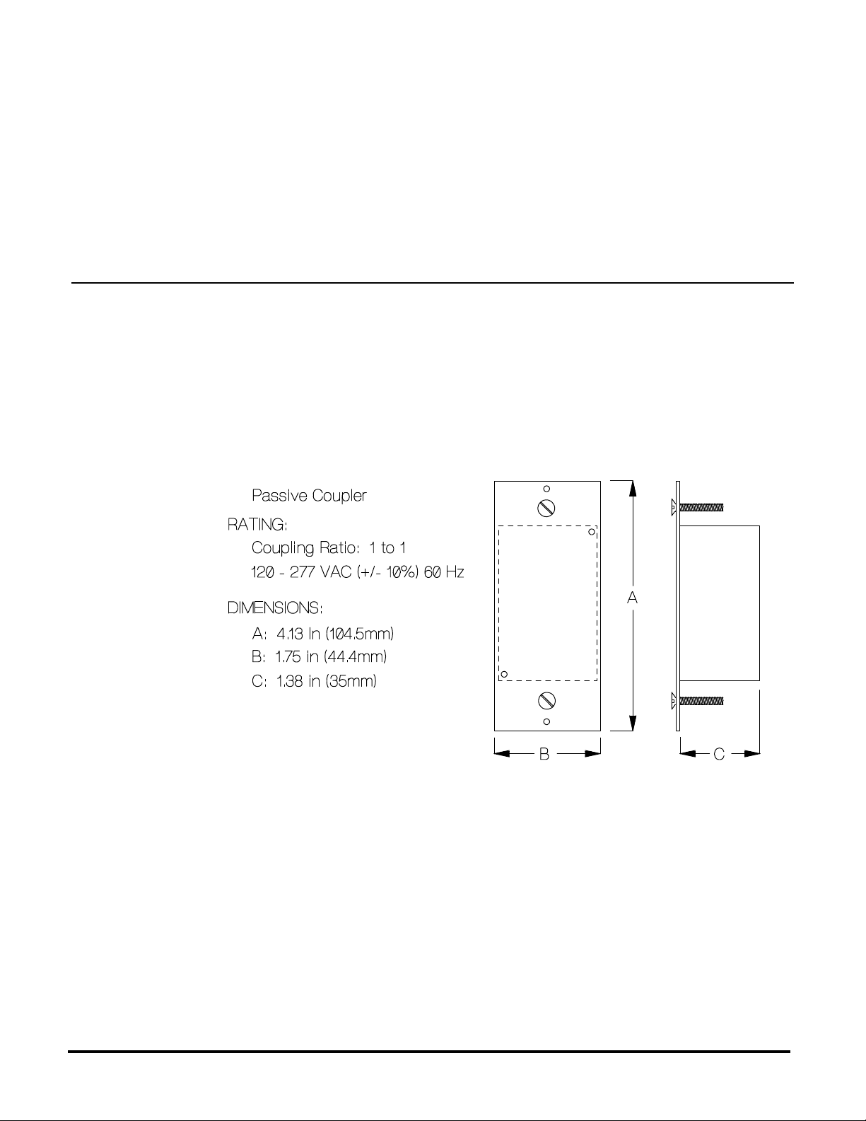
PCC 120/277 VAC 1:1 Ratio Passive Coupler
BEFORE YOU BEGIN...
READ ALL INSTRUCTIONS
Make sure your installation will conform to all applicable codes and requirements.
TEST FOR SIGNAL STRENGTH AND NOISE...
using the AR300 and AT300. It is necessary to test the installation in the actual operating
environment. The amount and types of line loads may reduce the strength of the transmitted signal
and/or electrical noise may cause interference with the transmitted signal. Proper installation may
require additional couplers, filters or repeaters. Special coupling devices are required to allow signal
to be distributed to all phases and zero-crossings in multi-phase and multi-transformer distributions.
IF YOU HAVE ANY QUESTIONS...
Consult your nearest Engineered System Center (ESC) for additional information.
There are no field repairable assemblies on this unit. It is covered by a two year limited warranty.
If service is needed, the unit must be returned to the ESC where purchased. Contact your ESC for
return details.
INSTALLATION
CAUTION! Make all connections with the POWER OFF to avoid injury to the installer or damage
to the device.
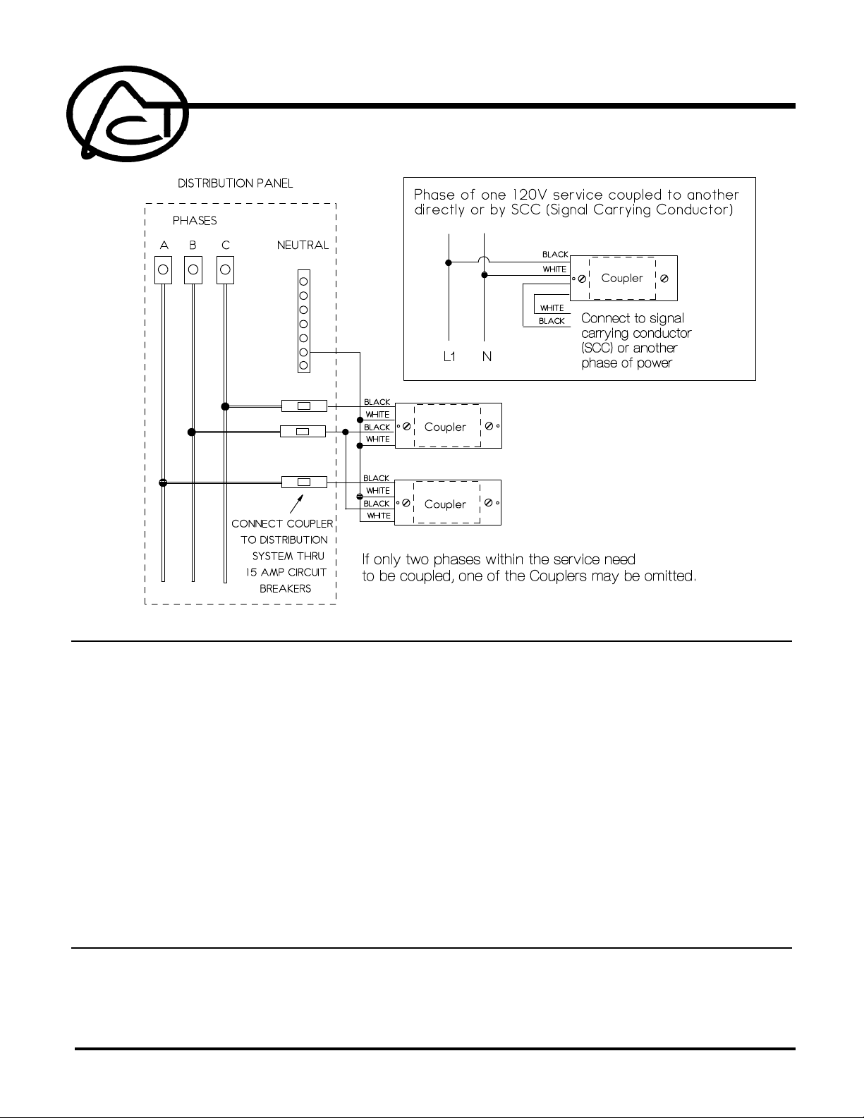
NOTE! The CP000 is designed to transfer command signals generated on one phase of a three
ADVANCED CONTROL TECHNOLOGIES, INC.
Indianapolis, Indiana 46278
1
CP000 Installation Instructions
P/D 022597
Page 2
CHECKOUT
phase system to one or more of the remaining phases. It will isolate phases from each other to
prevent trickle-through of line current from an energized phase to an inert phase.
1. Strip 3/4" of insulation from the ends of the conductors and make connections as shown in the
Wiring Diagram.
2. Check connections to be sure they are tight and no bare conductors are exposed.
3. Make sure the load or installation does not exceed the device rating.
4. Install into a standard single or multi-gang electrical wall box. Use a deep box to avoid
interference with box fittings and allow room for wiring connections.
Mount the device in the wallbox and install the cover plate.
1. Restore the power.
2. Transmit command signals from controller on one phase of coupled system and test for proper
response from receivers on other phase(s) of coupled system (and vice versa).
3. Test for Signal Strength and Noise once again across coupled system using the AR300 and
AT300.
CP000 Installation Instructions
P/D 022597
2
ADVANCED CONTROL TECHNOLOGIES, INC.
Indianapolis, Indiana 46278
 Loading...