

Page 1
AT004
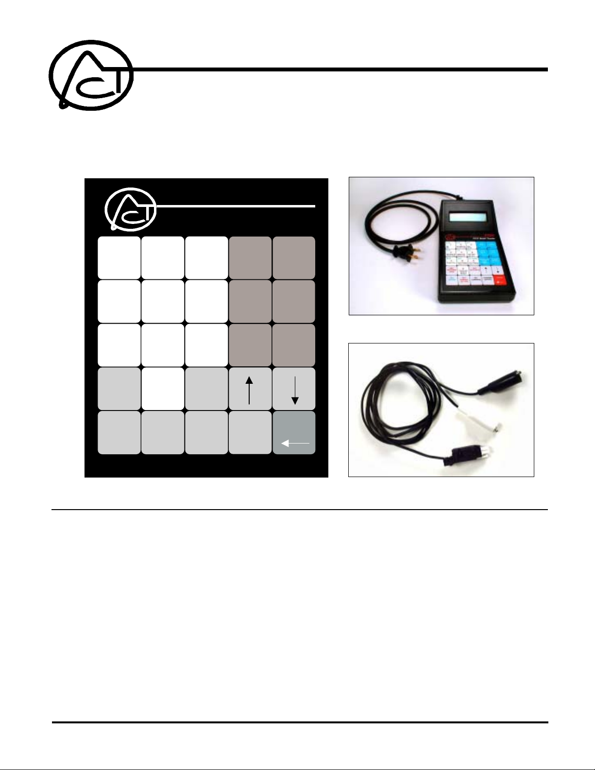
A10 Multi-Tester, 120 to 277 VAC Test Transceiver
The AT004 is an X10 Transceiver, able to send and receive A10 or standard X10 signals. Keypad selections
enable selection of transmit signal levels, single or continuous signal transmission, user selection of zero
crossing degree shift and display or log the level of noise or the data frames on the power line on AT004's LCD
screen.
AT004
PCC Multi-Tester
A B
1
On
Off
G H
All Lites Off
Status Rqst
M N
Preset Dim
SET
EXTENDED
CODE
SET
LETTER
4
7
C D
2
All Lites On
All Units Off
I J
5
Status On
Status Off
O P
8
Auto Repeat
(Address Only)
0
Press and
Hold for
Restart
SET
NUMBER
OR TYPE
BEFORE YOU BEGIN...
READ ALL INSTRUCTIONS
E F
3
Dim
Bright
K L
6
Hail Rqst
Hail Ack
P1 Auto
9
Auto Repeat
(Address On/Off)
SET
DATA BYTE
SET
COMMAND
LOG
NOISE
0xA
NOISE
DATA
0xC
SIGNAL and
NOISE
DATA
0xE
TRANSMIT
(ENTER)
LOG
FRAMES
0xB
SIGNAL
DATA
0xD
AT004 with 120V Cable
FRAME
DETAILS
0xF
PAUSE
208-277V Cable
CAUTION: This is a high voltage device. Use extreme caution around the power connections on
this product.
Notice: It is typical under normal operating conditions that the power supply within the AT004 will
get warm and the top of the enclosure will get warm to the touch. It is not meant for continuous
monitoring longer than 24 hours.
120 VAC operation versus 208 to 277 VAC operation:
The AT004 is designed so that the power supply switching is done internal to the cable, so there is
a difference in the two cables that are supplied.. NOTE: In order to maximize the life expectancy
of the power cables, do not disconnect them from the enclosure connector after use. Store the test
device with the cable connected. Only disconnect cable from enclosure connector when switching
from one cable to the other.
The device will not operate properly if the provided 208 to 277 VAC Clip cable (ACT Part Number
HW076) is used on 120 VAC The device will be over powered if the 120 VAC cable (ACT Part
Number HW080) is used on the higher, 208 to 277 VAC, power supply levels.
ADVANCED CONTROL TECHNOLOGIES, INC.
Indianapolis, Indiana 46278
0378-01
1
AT004 Operating Instructions
P/D 110409
Page 2

When connecting to 120 VAC outlet:
1. Using the provided polarized two-prong 120 VAC Plug Cable (ACT Part No. HW080), connect
the receptacle end to the white connector on the back of the enclosure. Make sure that it locks
in place and it cannot be removed without pressing the release tab.
2. Plug the polarized two-prong plug into any standard 120 VAC outlet.
3. The AT004 will automatically power up and start analyzing the power line.
When it is required to connect to 120 VAC within a Breaker Panel:
1. Use the Two-Prong 120 VAC Plug Cable (ACT Part No. HW080), with a purchased or
manufactured clip lead cable with a two-prong receptacle (not supplied). Plug this cable into the
adapter cable.
2. With the breaker turned off, connect the White (neutral) clip to the neutral within the breaker
panel.
3. Connect the Black (hot) clip directly on the screw of the breaker of the phase that you want to
test, or connect a wire to a breaker, and clip the line clip to this wire,
4. Turn on the breaker and observe that the AT004 powers up and begins to analyze the power line.
When connecting to 120 VAC (
1. Use the provided 208 to 277 VAC Alligator Clip Cable (ACT Part No. HW076), connect the
receptacle end to the white connector on the back of the enclosure. Make sure that it locks in
place and it cannot be removed without pressing the release tab.
2. With the breaker turned off, connect the White (neutral) clip to the neutral within the breaker
panel.
3. Connect the Black (hot) clip directly on the screw of the breaker of the phase that you want to
test, or connect a wire to that breaker and clip the line clip to this wire.
4. Turn on the breaker and observe that the AT004 powers up and begins to analyze the power line.
When connecting to 208 VAC or 240 VAC (60 Hz) line-to-line voltages:
1. Use the provided 208 to 277 VAC Alligator Clip Cable (ACT Part No. HW076), connect the
receptacle end to the white connector on the back of the enclosure. Make sure that it locks in
place and it cannot be removed without pressing the release tab.
2. With both of the breakers of the line-to-line voltage turned off, connect the White (neutral) clip
directly on the screw of one of the breakers of the line-to-line voltage that you are testing, or
connect a wire to that breaker and clip the line clip to this wire.
3. With both breakers still turned off, connect the Black (hot) clip directly on the screw of one of the
breakers of the line-to-line voltage that you are testing, or connect a wire to that breaker and clip
the line clip to this wire.
4. Turn on the two breakers and observe that the AT004 powers up and begins to analyze the lineto-line voltage.
USER LCD ADJUSTMENTS:
If the LCD display seems to dark or too light, the contrast can be adjusted with a potentiometer tuner
or a very small screwdriver on the left side of the enclosure near the bottom of the display bezel.
HOW TO OPERATE THE AT004
50 Hz) or 277 VAC:
The AT004 is a PCC test transmitter and test receiver. The following is a list of features available
on the AT004:
AT004 Operating Instructions
P/D 110409
1) Transmit and Receive X10 standard (including Preset Dim) and extended code
2) Report noise level on the power line
3) Report signal level on the power line
4) Noise and Frame Details
5) Auto transmit (P1- PON - POFF), ( A-P1), or (A-P1- A-PON - A-POFF)
6) Adjustable transmit voltage in 33.3mv increments.
7) Set Date / Time
8) Selectable 0°, 30°, 60°, 90°, 120°, 150° transmit pulse
9) Shows received X10 packets as one frame (signal data) or two frames (frame details)
0378-01
2
ADVANCED CONTROL TECHNOLOGIES, INC.
Indianapolis, Indiana 46278
Page 3

SECTION A. POWER UP
When power is applied to the AT004 the LCD will display the following for 2 seconds..
After 2 seconds, the LCD will display.....................................................................
After another 2 seconds the AT004 enters the SIGNAL AND NOISE DATA
MODE and the LCD will display.............................................................................
Title Screens can also be reached by holding the "Press and Hold for Restart" Button
for 5 seconds. Power does not have to be removed.
To Transmit go to Section B. Otherwise go to Section C.
SECTION B. TRANSMIT
All valid PCC codes will contain a letter code. To begin the process of
choosing a code to transmit, the SET LETTER key must be pressed.
ACT AT004 V1.0
A10 and X10
ACT AT004 V1.0
01-01-00 12:00
Noise X-10
700mv 0.00V
SET
LETTER
After pressing the SET LETTER key, the LCD will display.......................................
The letter can now be chosen by pressing the desired letter key
(shown in blue on the white keys on the keypad). The display will toggle
between the two letter codes when the key is pressed.
After selecting the desired letter, either the SET COMMAND, SET
NUMBER OR TYPE, or SET EXTENDED CODE key must be pressed.
COMMAND
If the SET COMMAND key is pressed, then the desired command
can be selected by pressing the appropriate key (commands are in
black on the white keys). The display will toggle between the two command
codes when the key is pressed.............................................................................
If the SET NUMBER OR TYPE key is pressed, then the desired number
can be selected by pressing the appropriate keys (numbers are in
red on the white keys)..........................................................................................
If the SET EXTENDED CODE is pressed, then you must enter
extended code information. More information on how to use the AT004
for extended code is given in SECTION J.
NORMALLY, you will want to enter a LETTER / NUMBER CODE,
then a LETTER / COMMAND combination. In this case, after the
letter code and number code has been entered as shown here (see next page)…......
Code to Transmit
A
SET
SET
NUMBER
OR TYPE
Code to transmit
A-on-
Code to transmit
A01
Code to Transmit
A01
SET
EXTENDED
CODE
ADVANCED CONTROL TECHNOLOGIES, INC.
Indianapolis, Indiana 46278
0378-01
3
AT004 Operating Instructions
P/D 110409
Page 4

SECTION B. TRANSMIT CONT’D
The letter key can be pressed again, and the display will show.....................
Code to Transmit
A01 A
(The desired letter can be selected as described above, but will likely
be the same as the letter in the first frame).................................................
Code to Transmit
A01 A-on-
The command can be entered after pressing the SET COMMAND
key described above
Press the TRANSMIT key to transmit the selected PCC code.
The LCD will display.................................................................................
TRANSMIT
(ENTER)
Code Transmitted
A01 A-on-
The code can be retransmitted by pressing the TRANSMIT KEY again.
(The “Code Transmitted” line will flash briefly to indicated another transmission.
Note that when a request command (HAIL REQUEST, STATUS REQUEST) is transmitted, the AT004
will automatically enter FRAME DETAILS mode so that any response can be seen.
To retransmit the request command, the SET LETTER key must be pressed. The request string
will automatically be setup on the LCD. To transmit the command again, press the TRANSMIT key.
Transmitting extended code is explained in SECTION J.
The use of AUTO commands available on the AT004 are explained in SECTION K.
To change Tx signal level or location, see Section L: Setup, Options 1 and/or 2
SECTION C. FUNCTION KEYS
To log noise, press the LOG NOISE key and go to Section D........................
To log signal, press the LOG FRAMES key and go to Section E....................
(NOTE: This function only gives frame details, not signal voltage).
To see noise data (average noise and noise at the zero crossing), press the
NOISE DATA key and go to Section F........................................................
To see signal data (signal strength, and X -10 code) press the SIGNAL DATA
key and go to Section G............................................................................
To see signal and noise data (X10 signal strength and noise strength),
press the SIGNAL and NOISE DATA key and go to Section H.....................
LOG
NOISE
0xA
LOG
FRAMES
0xB
NOISE
DATA
0xC
SIGNAL
DATA
0xD
SIGNAL and
NOISE
DATA
0xE
To see received X10 frames in detail, press the FRAME DETAILS key
and go to section I.....................................................................................
AT004 Operating Instructions
P/D 110409
0378-01
4
FRAME
DETAILS
0xF
ADVANCED CONTROL TECHNOLOGIES, INC.
Indianapolis, Indiana 46278
Page 5

SECTION D. LOG NOISE
When the LOG NOISE function key is pressed, the LCD will display...........................
Press 1, 3, or 6
Sample Rate (Min)
This is where the sample rate is selected. Pressing 1, 3, or 6 will select the 1, 3,
or 6 minute sample rate. Selecting 6 minutes will allow samples to be taken over a
24 hour period.
After 1, 3 , or 6 is selected the LCD will display...........................................................
#001 Log Start
01-01-00
After each sample is taken, the LCD will then display..............................................
#002 700mv 750mv
12:00:03 C
The #XXX will increment upon each sample being taken.
The first voltage reading is the average noise over 3 cycles and the second
voltage reading is the noise near the zero crossing.
The C stands for “Current”. The displaying of this letter indicates that the sample
number on the LCD is the most current sample available.
The UP/DOWN arrows can be used to scroll through the samples. When scrolling through the samples,
the C will disappear because the LCD is no longer displaying the most current sample. When the user
scrolls back to the most current sample, the C will reappear.
All noise levels displayed are peak to peak voltage levels.
SECTION E. LOG SIGNAL
When the LOG FRAMES function key is pressed, the LCD will display......................
The LCD will continue to display the above until a X10 code is received
When a new X10 code is received the LCD will display the X10 code as follows..........
After each X10 code is received the sample number (#XXX) will increment.
The C stands for “Current”. The displaying of this letter indicates that the sample number on the LCD is the most
current received X10 code.
The UP/DOWN arrows can be used to scroll through the log samples. When scrolling through the samples,
the C will disappear because the LCD is no longer displaying the most current sample. When the user
scrolls back to the most current sample, the C will reappear.
All signal levels displayed are peak to peak voltage levels.
#001 12:01:55
Log Start 10-12
#002 12:03:27
P01 P01 C
ADVANCED CONTROL TECHNOLOGIES, INC.
Indianapolis, Indiana 46278
0378-01
5
AT004 Operating Instructions
P/D 110409
Page 6

SECTION F. NOISE DATA
When the NOISE DATA function key is pressed, the LCD will display.....................
AVG RFI ZERO Cr
815mv 625mv
The noise readings will update about every ½ second.
The "AVG RFI" reading is the average noise over 3 cycles
The "ZERO Cr" reading is the noise that is present in the receive window after the zero crossing.
If the noise readings are above 5.0 Volts, “ >5.0V “ will be displayed. Noise levels are voltage peak to peak.
SECTION G. SIGNAL DATA
When the SIGNAL DATA function key is pressed, the LCD will display...................
The Voltage reading under X10 is the approximate voltage of the PCC
Signal voltage at the AT004.
The data under FRAMES is the actual received X10 code.
X-10 FRAMES
4.15V P01 PON
The display will only show one frame of two frame packets (P01P01). For example:
The display indicates that the AT004 received either P01P01 followed PONPON or it indicates
that the AT004 received P01 followed by PON. Note that this mode will not be useful in determining if
X10 code is from a repeater. Signal levels are voltage peak to peak.
SECTION H. SIGNAL AND NOISE DATA
When the SIGNAL and NOISE DATA function key is pressed, the LCD will display..
The noise reading is the noise present in the receive window after the zero crossing.
The X10 reading is the voltage of the received X10 code.
If the readings are above 5.0 Volts, “ >5.0V “ will be displayed.
Also, it is possible for the AT004 to receive a start code and then have the following
X10 code be corrupted. In this case, the display will show the following..................
Signal and noise levels are voltage peak to peak.
Noise X-10
815mv 4.25
Noise X-10
815mv -ERR-
AT004 Operating Instructions
P/D 110409
0378-01
6
ADVANCED CONTROL TECHNOLOGIES, INC.
Indianapolis, Indiana 46278
Page 7

SECTION I. FRAME DETAILS
When the FRAME DETAILS function key is pressed, the LCD will display................
When the first X10 code is received it will be displayed as follows.............................
When the next X10 code received it will cause the previous received code to
move up and the new code will take its place as follows..........................................
If only one frame is received the display will show one frame followed by “——-“ .......
This is useful in determining if PCC code is from a repeater.
SECTION J. EXTENDED CODE TRANSMITTING
All valid extended PCC code will contain a letter code. To begin the process of
choosing a code to transmit, the SET LETTER key must be pressed......................
After pressing the SET LETTER key, the LCD will display.......................................
The letter can now be chosen by pressing the desired letter key
(shown in blue on the white keys on the keypad). The display will toggle
between the two letter codes when the key is pressed.
1&2
3&4
1&2
3&4 P01 P01
1&2 P01 P01
3&4 PON PON
1&2 PON PON
3&4 PON ------
SET
LETTER
Code to Transmit
A
After selecting the desired letter, to setup an extended
code packet the SET EXTENDED CODE key must be pressed...............................
The LCD will display....................................................................................................
The SET NUMBER key should be pressed, then the desired number
can be selected by pressing the appropriate keys (numbers are in
red on the white keys)..................................................................................................
You must then enter extended code information.
The SET DATABYTE key should be pressed.............................................................
The desired byte can be selected by pressing the appropriate keys (number
keys that are in red and the additional hexadecimal numbers in black located
on the blue keys...........................................................................................................
After entering the databyte, the TYPE must be selected. Press the SET NUMBER or
TYPE key.....................................................................................................................
After pressing this key, the TYPE can be selected by using the number keys
or the hexadecimal keys..............................................................................................
After entering the type, the command must be selected. Press the SET
COMMAND key...........................................................................................................
After pressing the SET COMMAND key, the command can be entered by using the
number keys or the hexadecimal keys.
Press the TRANSMIT key to transmit.
SET
EXTENDED
CODE
Code to Transmit
A[1]
Code to Transmit
A[1]16
SET
DATA BYTE
Code to Transmit
A[1]16FD
SET
NUMBER
OR TYPE
Code to Transmit
A[1]16FD1
Code to Transmit
A[1]16FD1F
ADVANCED CONTROL TECHNOLOGIES, INC.
Indianapolis, Indiana 46278
0378-01
7
AT004 Operating Instructions
P/D 110409
Page 8

SECTION K. AUTO FUNCTIONS
There are several auto functions available on the AT004.
P1AUT0, LETTER CODE REPEAT, and LETTER CODE ON/OFF REPEAT...........
Code to Transmit
A
After pressing the LETTER CODE key, the LCD will display..................................
Code to Transmit
P1Auto
To Select P1AUTO, press the P1AUTO key. The LCD will display..........................
Code Transmitted
P1Auto
Press the TRANSMIT key to begin transmitting P1 PON POFF.
To Choose an auto-repeat "alpha one" address with ON/OFF command (i.e. A1, B1, C1...through P1):
Press the LETTER key, and then choose a letter.
Then Press the COMMAND key and choose AUTO REPEAT address on/off..........
Code Transmitted
BrptOnOf
Press the TRANSMIT key to begin transmitting the selected letter code with the
ON and OFF commands. NOTE: Only a "numerical 1" address is available for Auto-Repeat
To only transmit an "alpha one" address with no command:
Press the LETTER key, and then choose a letter.
Then Press the COMMAND key and choose AUTO REPEAT (address only).........
Code Transmitted
BrptAddr
Press the TRANSMIT key to begin transmitting the selected letter code without the
ON and OFF commands.
The PAUSE key can be used to temporarily suspend transmission of any auto transmission. It can be pressed
again to restart it.
SECTION L . SETUP
When power is applied to the AT004 the LCD will display the following for 2 seconds.
After 2 seconds, the LCD displays......................................................................
During these 4 seconds, you can press the PAUSE key to enter SETUP mode.....
You can use the UP/DOWN buttons to scroll through the SETUP OPTIONS as follows:
1. Tx Voltage
2. Tx Location
3. Set Time/Date
4. Clear Logs
5. Exit
ACT AT004 V1.0
A10 and X10
ACT AT004 V1.0
01-01-00 12:00
Setup Menu
1. TX Voltage
AT004 Operating Instructions
P/D 110409
0378-01
8
ADVANCED CONTROL TECHNOLOGIES, INC.
Indianapolis, Indiana 46278
Page 9

After entering the SETUP mode, you can then select the desired OPTION
by pressing the appropriate number key.
OPTION 1 Tx Voltage
You can enter the desired transmit voltage by pressing
The number keys and then pressing the ENTER key............................................
For example, if you enter 100 as the Tx level, then the
user can expect approximately 3.30 volts (p-p) of transmit signal.
If you enter anything above 150, the output will go to its
MAXIMUM output setting. (Approximately 6 Vp-p)
OPTION 2. Tx Location
The display will query the user whether it is desired to transmit
at certain locations on the 60Hz or 50Hz sine wave..............................................
Press 1 or 2 to activate or deactivate transmissions at that location.
OPTION 3. Set Time/Date
Use the number keys to select the desired TIME OF DAY. (24 hour format).
The LEFT ARROW located on the PAUSE key can be used to make any corrections.
After the desired time is entered, the user must press the ENTER key...................
After pressing ENTER, the LCD will display.........................................................
In the same manner as described above, the DATE can be selected.
After selecting the desired DATE, the ENTER key must be pressed.
1-150 X 33.3mv
>150 = MAX [255]
1 = YES 2 = NO
Transmit 0O?
Set Time
12:00:00
Set Date
01-01-00
OPTION 4. Clear Logs
When you select the CLEAR LOGS option, the LCD will display...........................
Pressing 1 will CLEAR the NOISE LOG and the FRAMES LOG.
Pressing 2 will exit out of this option without clearing the log.
OPTION 5. Exit.
Selecting OPTION 5 will exit SETUP mode and the AT004 will enter
NORMAL OPERATION.
CARE AND CLEANING OF KEYPAD SURFACE
Keypad can be cleaned with the following cleaners without staining:
Top Job Fantastic Formula 409 Ajax Windex
Keypad can be exposed to the following without visible staining, but suggest removing within 24 hours:
Grape Juice Coffee Milk
Avoid prolonged contact with:
Tomato Juice Ketchup Lemon Juice Mustard
Are You Sure?
1 = Yes 2 = No
ADVANCED CONTROL TECHNOLOGIES, INC.
Indianapolis, Indiana 46278
0378-01
9
AT004 Operating Instructions
P/D 110409
 Loading...