

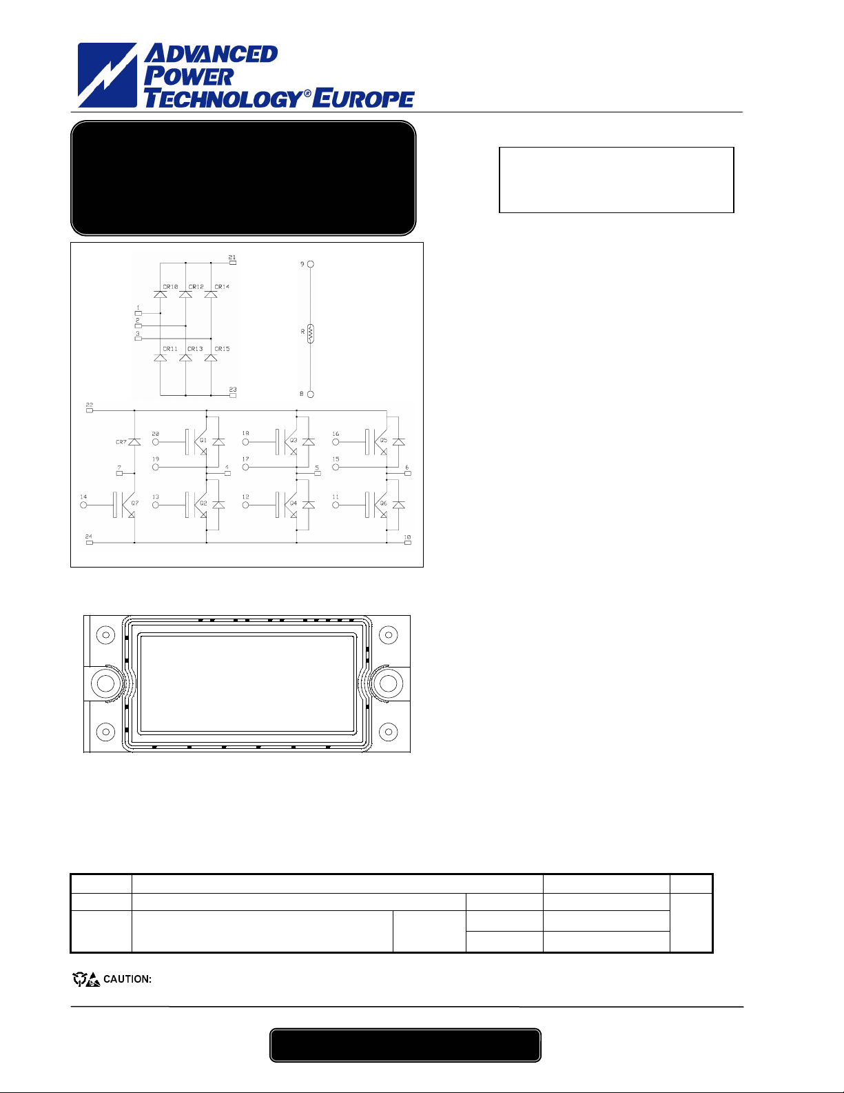
APTGS25X120RTP2
APTG
S
25
X
120
B
TP
2
1 - 4
N
PT IGBT Power Mod
ule
Input rectifier bridge +
Brake + 3 Phase Bridge
APTGS25X120RTP2: Without Brake (Pin 7 & 14 not connected)
14
21
22
23
24
1 2 3 4 5 6
All ratings @ Tj = 25°C unless otherwise specified
101118 16
1315171920
12
9
8
7
Application
• AC Motor control
Features
• Non Punch Through (NPT) Low Loss IGBT®
• Very low stray inductance
• High level of integration
• Internal thermistor for temperature monitoring
Benefits
• Low conduction losses
• Stable temperature behavior
• Very rugged
• Solderable terminals for easy PCB mounting
• Direct mounting to heatsink (isolated package)
• Low junction to case thermal resistance
• Easy paralleling due to positive TC of VCEsat
• Low profile
1. Absolute maximum ratings
Diode rectifier
Symbol Parameter Max ratings Unit
V
Repetitive Peak Reverse Voltage 1600
RRM
ID DC Forward Current
I
Surge Forward Current tp = 10ms
FSM
Absolute maximum ratings
These Devices are sensitive to Electrostatic Discharge. Proper Handing Procedures Should Be Followed.
V
= 1200V
CES
IC = 25A @ Tc = 80°C
- Low voltage drop
- Low tail current
- Switching frequency up to 20 kHz
- Soft recovery parallel diodes
- Low diode VF
- Low leakage current
- Avalanche energy rated
- RBSOA and SCSOA rated
TC = 80°C
Tj = 25°C
Tj = 150°C
25
300
230
V
A
APT website – http://www.advancedpower.com
APTGS25X120BTP2 – Rev 0 July, 2003
APTGS25X120RTP2
APTG
S
25
X
120
B
TP
2
2 - 4
IGBT & Diode Brake
Symbol Parameter Max ratings Unit
V
Collector - Emitter Breakdown Voltage 1200
CES
IC Continuous Collector Current
ICM Pulsed Collector Current TC = 25°C 25
VGE Gate – Emitter Voltage ±20 V
PD Maximum Power Dissipation
IF DC Forward Current
IGBT & Diode Inverter
Symbol Parameter Max ratings Unit
V
Collector - Emitter Breakdown Voltage 1200
CES
IC Continuous Collector Current
ICM Pulsed Collector Current TC = 25°C 50
VGE Gate – Emitter Voltage ±20 V
PD Maximum Power Dissipation
SCSOA Short circuit Safe Operating Area
IF DC Forward Current
I
Surge Forward Current tp = 1ms
FSM
2. Electrical Characteristics
Diodes Rectifier
Symbol Characteristic Test Conditions Min Typ Max Unit
IR Reverse Current VR = 1600V Tj = 150°C
VF Forward Voltage
R
Junction to Case 1
thJC
IGBT Brake & Diode
Symbol Characteristic Test Conditions Min Typ Max Unit
I
Zero Gate Voltage Collector Current
CES
V
Collector Emitter on Voltage
CE(on)
V
Gate Threshold Voltage VGE = V
GE(th)
I
Gate – Emitter Leakage Current VGE = 20V, VCE = 0V 300 nA
GES
C
Input Capacitance
ies
VF Forward Voltage
R
Junction to Case
thJC
(only for APTGS25X120BTP2)
Absolute maximum ratings
Electrical Characteristics
(only for APTGS25X120BTP2)
Absolute maximum ratings
TC = 25°C
TC = 80°C 12.5
TC = 25°C
TC = 80°C
TC = 25°C
TC = 80°C 25
TC = 25°C
Tj = 125°C
TC = 80°C
TC = 80°C
IF = 30A
IF = 25A
Electrical Characteristics
VGE = 0V
VCE = 1200V
VGE =15V
IC = 12.5A
CE
VGE = 0V, VCE = 25V
f = 1MHz
VGE = 0V
IF = 25A
Tj = 25°C
Tj = 150°C
Tj = 25°C
Tj = 125°C
Tj = 25°C
Tj = 125°C
, IC = 0.35 mA 4.5 5.5 6.5 V
Tj = 25°C 2.05 2.4
Tj = 125°C
20
100 W
25 A
45
230 W
160A @ 720V
25
50
2 mA
1.3 1.5
1.05 1.1
0.5 500 µA
0.8 mA
2.7 3.15
3.1
600 pF
1.9
IGBT 1.2
Diode 1.2
V
A
V
A
A
V
°C/W
V
V
°C/W
APT website – http://www.advancedpower.com
APTGS25X120BTP2 – Rev 0 July, 2003

APTGS25X120RTP2
APTG
S
25
X
120
B
TP
2
3 - 4
RMS Isolation Voltage, any terminal to case t =1 min,
IGBT & Diode Inverter
Symbol Characteristic Test Conditions Min Typ Max Unit
BV
Collector - Emitter Breakdown Voltage VGE = 0V, IC = 500µA
CES
I
Zero Gate Voltage Collector Current
CES
V
Collector Emitter on Voltage
CE(on)
V
Gate Threshold Voltage VGE = V
GE(th)
I
Gate – Emitter Leakage Current VGE = 20V, VCE = 0V 300 nA
GES
C
Input Capacitance
ies
T
Turn-on Delay Time 45
d(on)
T
Rise Time 45
r
T
Turn-off Delay Time 290
d(off)
T
Fall Time
f
T
Turn-on Delay Time 45
d(on)
T
Rise Time 45
r
T
Turn-off Delay Time 340
d(off)
T
Fall Time 80
f
E
Turn off Energy
off
VF Forward Voltage
Qrr Reverse Recovery Charge
R
Junction to Case
thJC
Temperature sensor NTC
Symbol Characteristic Min Typ Max Unit
R25 Resistance @ 25°C
B
T
25/50
= 298.16 K 3375 K
25
3. Thermal and package characteristics
Symbol Characteristic Min Typ Max Unit
V
ISOL
I isol<1mA, 50/60Hz
TJ Operating junction temperature range
T
Storage Temperature Range -40 125
STG
TC Operating Case Temperature -40 125
Torque
Wt Package Weight
Mounting torque To Heatsink M5
Electrical Characteristics
R
=
R
T
exp
25
B
50/25
25
1200
VGE = 0V
VCE = 1200V
VGE =15V
IC = 25A
CE
VGE = 0V, VCE = 25V
f = 1MHz
Inductive Switching (25°C)
VGE = ±15V
V
= 600V
Bus
IC = 25A
RG = 27Ω
Inductive Switching (125°C)
VGE = ±15V
V
= 600V
Bus
IC = 25A
RG = 27Ω
VGE = 0V
IF = 25A
IF = 25A
VR = 600V
di/dt=800A/µs
T: Thermistor temperature
11
−
RT: Thermistor value at T
TT
Tj = 25°C
Tj = 125°C 2 mA
Tj = 25°C
Tj = 125°C
, IC = 1mA 4.5 5.5 6.5 V
Tj = 25°C
Tj = 125°C
Tj = 25°C
Tj = 125°C
IGBT 0.55
Diode 1.2
1.5 500 µA
2.1 2.55
2.45
1500 pF
60
3.2 mJ
2.05 2.5
1.9
2.1
4.5
5
2500 V
-40 150
3.3
185
V
V
ns
ns
V
µC
°C/W
kΩ
°C
N.m
g
APT website – http://www.advancedpower.com
APTGS25X120BTP2 – Rev 0 July, 2003

APTG
S
25
X
120
B
TP
2
4 - 4
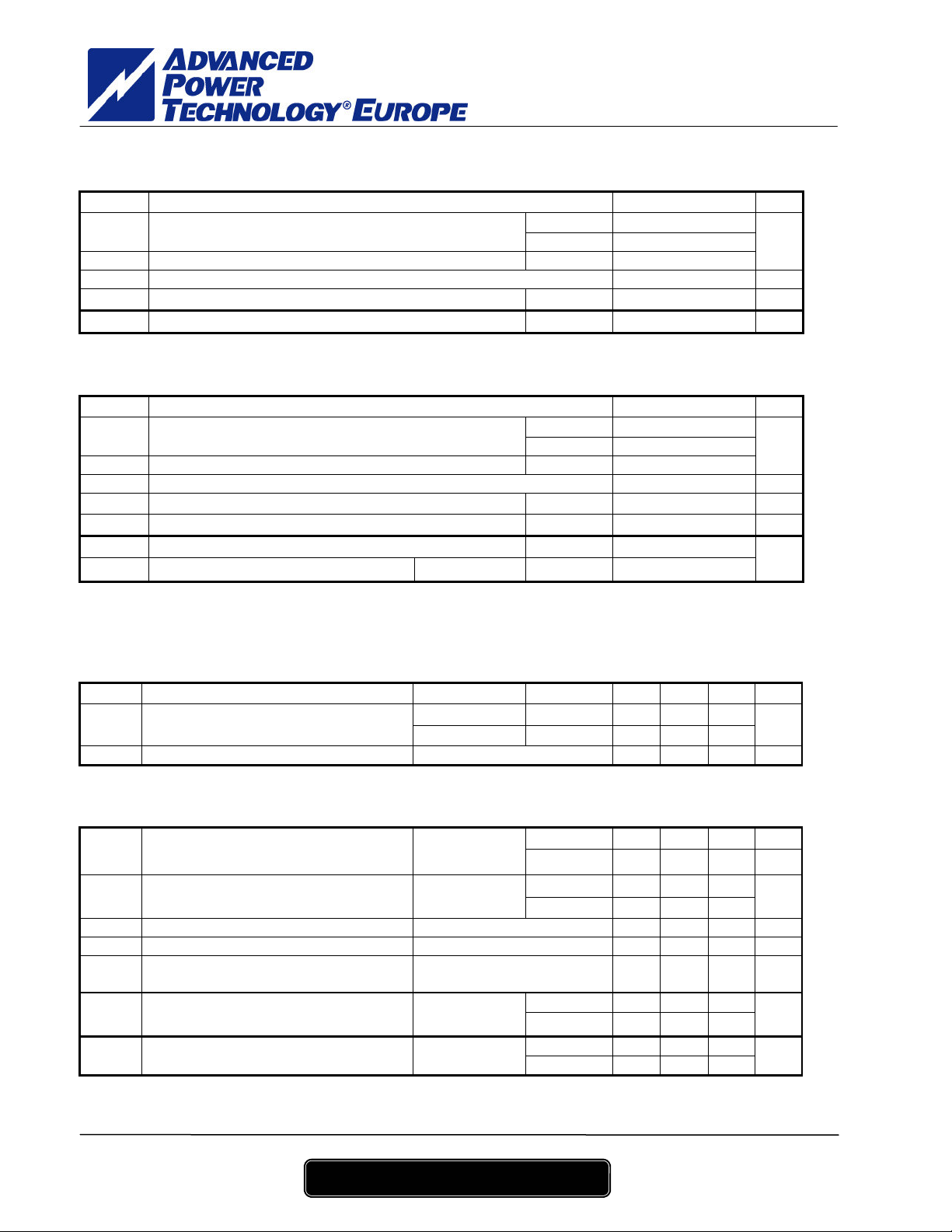
4. Package outline
APTGS25X120RTP2
PIN 1
PIN 24
ALL DIMENSIONS MARKED " * " ARE TOLERENCED AS :
APT reserves the right to change, without notice, the specifications and information contained herein
APT's products are covered by one or more of U.S patents 4,895,810 5,045,903 5,089,434 5,182,234 5,019,522
5,262,336 6,503,786 5,256,583 4,748,103 5,283,202 5,231,474 5,434,095 5,528,058 and foreign patents. U.S and Foreign patents pending. All Rights Reserved.
APT website – http://www.advancedpower.com
APTGS25X120BTP2 – Rev 0 July, 2003
 Loading...