

Page 1

ADV ANCE ADAPTERS, INC.
4320 Aerotech Center Way, Paso Robles, CA 93446
ASSEMBLY INSTRUCTION SHEET
Page 1 of 12 Rev. Date: 07-14-10 P/N AB1000 & AB1001
ATLAS 2 SPEED REBUILD KITS
P/N AB1000 32sp front output
Qty Part No. Description
1 300314 REAR OUTPUT BEARING
2 300355 CLUSTER THRUST WASHERS
2 300358 O-RING CLUSTER SHAFT
4 300370 BRAS SYNCRO RINGS
6 300372 SYNCRO DOGS
4 300373 SYNCRO DOR SPRINGSS
4 300383 SHIFT FORK PADS
2 300386 SET SCR EW F OR SHIFT FORK
2 300387 SEAL FOR SHIFT RAIL
1 300393 FRONT OUTPUT THRUST WASHER
2 300474 RUBBER SEAL YOKE WASHER
2 300476 YOKE NUTS
3 300490 O-RING FOR INPUT AND OUTPUTS
6 300491 TAILHOUSING BEARING SHIMS
1 300499 FRONT INPUT SEAL
1 300500 FRONT INPUT SEAL
1 300509 FRONT OUTPUT THRUST WASHER
1 300510 FRONT INPUT BEARING
1 300511 FRONT OUTPUT BEARING
1 300512 FRONT OUTPUT BEARING
2 300513 REAR OUTPUT BEARING
1 300514 REAR OUTPUT BEARING
1 300515 OUTPUT SHAFT POCKET BEARING
2 300516 CLUSTER GEAR BEARINGS
2 300517 HIGH GEAR BEARINGS
2 300518 LOW SPEED GEAR BEARINGS
1 300919 DRAIN PLUG SEAL WASHER
1 301400 PAN GASKET
1 716453 SNAP RING
1 716455 SNAP RING
6 300105S FRONT HOUSING BEARING SHIMS
P/N AB1001 26sp front output
Qty Part No. Description
1 300314 REAR OUTPUT BEARING
2 300355 CLUSTER THRUST WASHERS
2 300358 O-RING CLUSTER SHAFT
4 300370 BRAS SYNCRO RINGS
6 300372 SYNCRO DOGS
4 300373 SYNCRO DOR SPRINGSS
4 300383 SHIFT FORK PADS
2 300386 SET SCR EW F OR SHI FT F OR K
2 300387 SEAL FOR SHIFT RAIL
1 300474 RUBBER SEAL YOKE WASHER
1 300476 YOKE NUTS
1 300478 FRONT YOKE NUT
1 300480 FRONT YOKE SEAL WASHER
3 300490 O-RING FOR INPUT AND OUTPUTS
6 300491 TAILHOUSING BEARING SHIMS
1 300499 FRONT INPUT SEAL
1 300500 FRONT INPUT SEAL
1 300501 FRONT OUTPUT SEAL
2 300509 FRONT OUTPUT THRUST WASHER
1 300510 FRONT INPUT BEARING
2 300511 FRONT OUTPUT BEARING
2 300512 FRONT OUTPUT BEARING
1 300513 REAR OUTPUT BEARING
1 300514 REAR OUTPUT BEARING
1 300515 OUTPUT SHAFT POCKET BEARING
2 300516 CLUSTER GEAR BEARINGS
2 300517 HIGH GEAR BEARINGS
2 300518 LOW SPEED GEAR BEARINGS
1 300919 DRAIN PLUG SEAL WASHER
1 301400 PAN GASKET
1 716453 SNAP RING
1 716455 SNAP RING
6 300105S FRONT HOUSING BEARING SHIMS
NOTE: We have not included the 32 spline yoke seals in these kits due to the two yoke diameters. These seals
must be ordered separtly. The caged bearing that fit the in the rear output shaft is not included in this kit, it is a
low wear bearing and is very difficult to remove.
Page 2
ADV ANCE ADAPTERS, INC.
4320 Aerotech Center Way, Paso Robles, CA 93446
ASSEMBLY INSTRUCTION SHEET
Page 2 of 12 Rev. Date: 06-18-08 P/N AB1000 & AB1001
ATLAS 2 SPEED REBUILD KITS
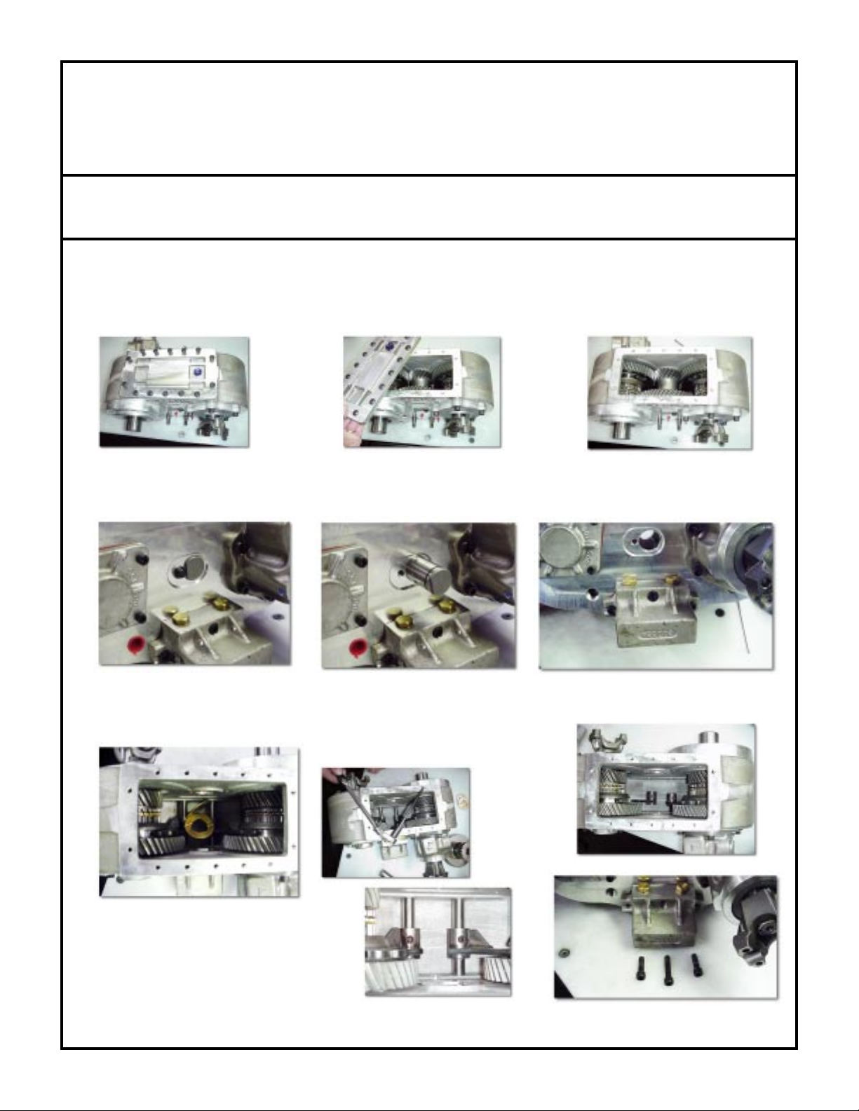
Remove the transfer case from the vehicle.
Remove the drain plug and the drain oil.
Remove (14) torx head bolts and remove the inspection cover. Clean the surface of any debris.
Remove the cluster pin retaining the bolts.
Remove the cluster pin from the unit.
Remove the cluster gear.
Remove the two thrust washers from inside the case.
You should now have access to the shift fork set screws which need to be removed.
Remove the three bolts from the shifter control.
Page 3
ADV ANCE ADAPTERS, INC.
4320 Aerotech Center Way, Paso Robles, CA 93446
ASSEMBLY INSTRUCTION SHEET
Page 3 of 12 Rev. Date: 06-18-08 P/N AB1000 & AB1001
ATLAS 2 SPEED REBUILD KITS
Using a plastic dead blow hammer, use one hand to support the Atlas shift forks inside the case to prevent binding
on the shift rails and the other hand on the hammer, lightly tapping the shift rails from the front of the case. This
provides an easy way of pulling the shifter control from the Atlas case. Once the shift control is removed, clean
both the case and shifter control mating surfaces.
Remove the forks from the case. (Note: If you have Atlas case
#1929 or earlier and have not upgraded your shifter forks, this is an
ideal time to install new shift forks, P/N 301550).
Remove the 5 bolts from the front output shaft retainer and the 4 rear bearing cap bolts. Remove the front assembly
from the Atlas case. Note: The low range gear, bearing, spacer, and rear bearing will be left in the case.
Remove the front yoke nut and front retainer. Remove the bearing and spacer. The gear and needle bearing can
then be removed.
Page 4
ADV ANCE ADAPTERS, INC.
4320 Aerotech Center Way, Paso Robles, CA 93446
ASSEMBLY INSTRUCTION SHEET
Page 4 of 12 Rev. Date: 06-18-08 P/N AB1000 & AB1001
ATLAS 2 SPEED REBUILD KITS
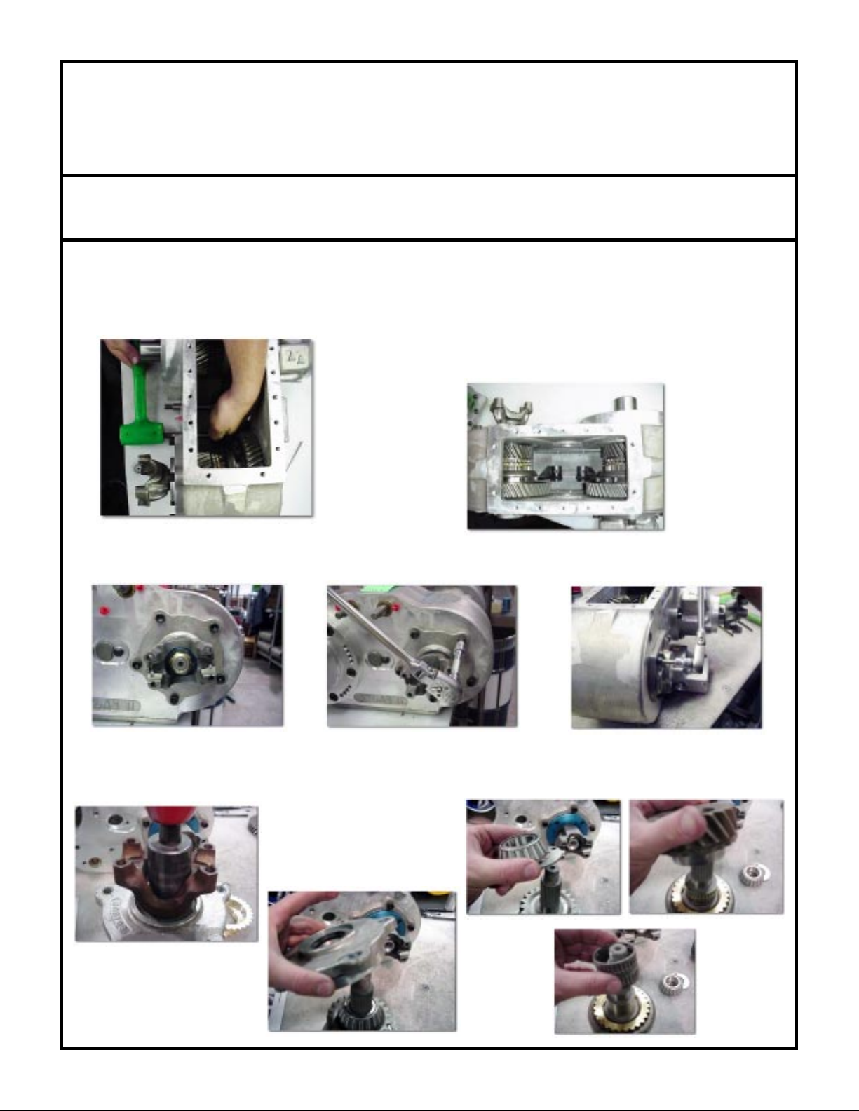
Next, remove the shifter slider, the synchronizer springs, the synchronizer dogs and the brass rings.
Turn the case so that you are looking at the input ring. Remove the six bolts that hold it to the case. Use your dead
blow hammer to firmly hit the side of the transfer case while pulling on the input shaft. The tolerance on the input bore
should be a snug fit and may take a little while to work loose. We do not recommend using any type of prying mechanism
to get the input out; the aluminum is "softer" than a screwdriver or a pry bar and WILL get damaged and my cause
problems down the road. Once removed, there will be one synchro ring that will become free. Remove it from the
case, and place it in top of the synchro hub located on the input assembly you just removed.
Using your fingers, "pop" the synchro slider off the slider hub. When removed, three synchro dogs will become loose.
They may simply "fall" out or even "spring" out.
Remove the speedometer drive from the tail housing. If you have no speedometer drive but do have a freeze plug
blocking the hole, disregard and go to the next step.
Using an 1-1/8" socket, remove the output shaft nut and discard it. Depending on the mileage of your unit, the rear
yoke may be difficult to remove. You can use a puller if it is stubborn but most yokes can be removed with the use
of a dead blow hammer. When the nut and yoke are off, the output shaft will become "loose" in the case. DO NOT
ATTEMPT TO REMOVE THE OUTPUT SHAFT FROM THE CASE YET! There are a couple of parts which
are still holding it into the case.
Remove the five bolts holding the tail housing on the case. You may need to tap the tail housing to get it loose from
the case. Take the housing completely off the case and set it aside.
Use a set of snap ring pliers to remove the first snap ring from the shaft. Next, remove the blue plastic drive gear from
the shaft (may be a slightly snug fit). Remove the last snap ring and set those parts aside.
The last thing holding the shaft into place is the bearing on it. This bearing is another "light" press, and will require the
use of the dead blow hammer. Use one hand to hit the tip of the shaft with the hammer and the other hand to support
the large "pancake" gear inside the case. Visualize that you are driving the output shaft through the pancake gear and
out the front of the case. When the bearing becomes loose, slide it completely off of the shaft. Place it into the "old"
parts section. Pull the shaft fully from the front of the case. There is one more brass synchro slider, and one caged
needle bearing set that are now free. Remove the pancake gear from the case. There should not be any more parts
loose inside the case. At this point it is wise to clean and inspect your case and parts for any debris. Also inspect the
outside of the case and remove any silicon or sealing material.
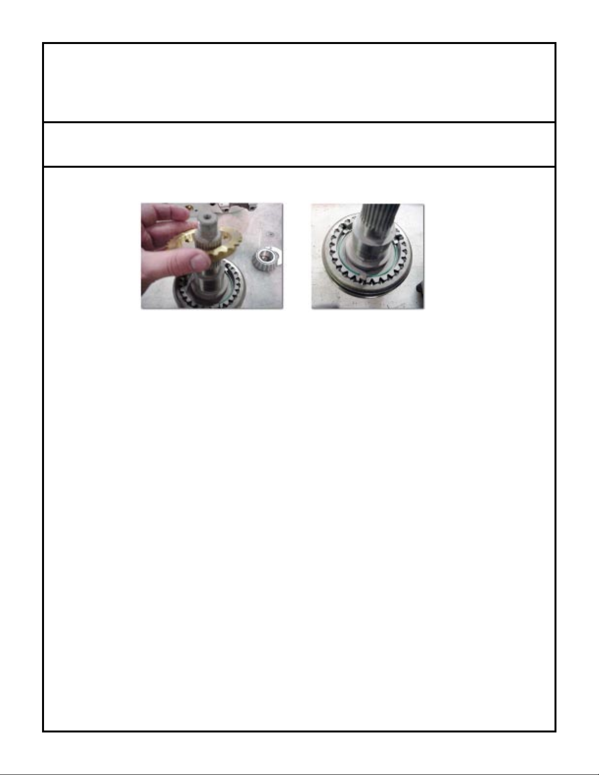
Place the pancake gear on a flat surface with the synchro hub facing up. Take one of the brass synchro rings and place
Page 5

ADV ANCE ADAPTERS, INC.
4320 Aerotech Center Way, Paso Robles, CA 93446
ASSEMBLY INSTRUCTION SHEET
Page 5 of 12 Rev. Date: 06-18-08 P/N AB1000 & AB1001
ATLAS 2 SPEED REBUILD KITS
it over the hub. Press it down firmly so that it gets "stuck" and holds in place. Position the gear into the case. The
synchro ring side should be facing the front of the T/C. With a small amount of oil, lubricate the appropriate caged
needle bearing and slid it into the pancake gear.
Place your synchro slider over the shaft and align the teeth so it sits all the way to the bench. Find your three
synchro dogs. Place them into the slotted area of the shaft. They should be placed with the "dimpled" side
towards the slider. Once all three are in, grab one of your green synchro springs and snap it into the assembly.
Make sure that it contacts all three of the dogs below the retaining lip. Carefully flip this assembly over, keeping
the slider from slipping off the shaft. You should now be able to get the second synchro spring into the three
dogs, identical to the other side. Wiggle the slider very slightly on the shaft to make sure the three dogs are hitting
their "dimples" inside the slider, which will hold them all on the shaft.
Once the Atlas tailhousing is disassembled the old bearings and races will need to be pressed out of this aluminum
housing. Once the new races are installed you will need to set and check the end play. The bearings should have
.001" - .003" of end play. When checking the endplay you do not need to have the gear on the shaft. Place the
large bearing on the shaft so that it seats to the shoulder on the shaft, pick one of the shims and measure it. Place
the shim on the shaft with the chamfer end going on first. Slip the shaft into the tailhousing and then put the smaller
bearing in place. Put the yoke on the shaft and use the old rear locking nut to secure the yoke to the shaft. You
will now need to check the in and out movement of the shaft in the tailhousing. We recommend securing the Atlas
case to a bench and bolting the tailhousing to the case. Once the assembly is bolted together, take a dead blow
hammer and hit the shaft assemble downward to make sure the bearings are set into place. Set a dial indicator
on the output shaft and use a pry bar to apply pressure to the shaft assembly to see how much movement is in
the bearings. If the bearings have no movement then you must go to a thicker shim and to much play would be
a thinner shim. Repeat this procedure until the .001"-.003" is obtained. Once the new shim is selected follow
the procedures for assembly into the Atlas case.
Page 6

ADV ANCE ADAPTERS, INC.
4320 Aerotech Center Way, Paso Robles, CA 93446
ASSEMBLY INSTRUCTION SHEET
Page 6 of 12 Rev. Date: 06-18-08 P/N AB1000 & AB1001
ATLAS 2 SPEED REBUILD KITS
Without disturbing the synchro assembly, guide the output shaft through the front of the case, and through the pancake
gear. Pay attention to the caged needle bearing inside the pancake. It will get pushed out slightly, so you will need
to take your other hand and guide it through. THE FOLLOWING PORTION OF THIS STEP IS VERY
IMPORTANT! When guiding the shaft fully into the pancake, you must rotate the shaft until the notches of the brass
synchro ring engage the three dogs. Remember from the previous steps that you "stuck" the brass ring to the pancake.
As soon as the three dogs contact the notches, the shaft will seat a little further into the gear, and break the synchro
ring loose. You can check the engagement by pulling the output shaft tight against the pancake and still be able to
"jiggle" the brass synchro ring slightly. If it is tight, rotate the shaft some more until it does engage correctly. Repeat
this step if necessary, but still be careful to not pull the synchro slider off .
Assembly hint:
Hold the output shaft in your hand. You want to have the three notches over you thumb and fore finger. Slip the slider
over the shaft and drop in the three synchro dogs. Roll the spring onto the two of the dogs and then snap it into the
third and flip shaft over and repeat this step.
Page 7

ADV ANCE ADAPTERS, INC.
4320 Aerotech Center Way, Paso Robles, CA 93446
ASSEMBLY INSTRUCTION SHEET
Page 7 of 12 Rev. Date: 06-18-08 P/N AB1000 & AB1001
ATLAS 2 SPEED REBUILD KITS
Next to go on is the roller tapered bearing (the larger of the two new bearings). Preferably, it needs to be pushed on
by hand. Please put adequate pressure on the output shaft so it does not slip out of the synchro dog grooves. If it fits
a bit tighter than what you can do by hand, you can take a drift or brass punch to tap it on. Please try to only tap on
the inner race, the outer cage can get damaged very easily. When the bearing is fully seated, rotate the shaft one more
time to check the dog alignment.
Locate the new output shim and slide it over the shaft. Put the shim on the shaft with the "heavy chamfer" side down.
This shim is simply a piece of steel that has been machined to a specific thickness. This thickness determines the
endplay of the shaft.
Grab the new rear housing and stretch the new square "o-ring" over it. We have included two new seals with your
upgrade kit. Select the correct one that fits your yoke, but do not press it into the casting yet. Locate the smaller tapered
roller bearing. Take this bearing and place it into the correct race (which is pressed into the casting). Make sure you
have placed it with the rollers towards the race. Carefully press the seal into the casting until it is flush. Slide this
assembly over the shaft and guide it until it centers into the case. When the housing has been placed up to the case,
rotate until the holes are lined up. Use silicon on the 5 new bolts, and torque them to 25 ft./lbs. Try and use a star
type pattern when you torque the bolts.
You should now have the tailhousing secure to the back of the transfer case. The output shaft will be loose still, so
be careful not to let the dogs become miss-aligned. You are ready for the yoke. Find the new plastic yoke spline washer
and place it over the threaded portion of the shaft. Take the yoke and hold it with the "u-joint" side away from you.
Place a small bead of silicon around the inside of the spline portion. Lubricate the seal with a small amount of oil and
start the yoke on shaft about 1/2 of an inch only. Start the new nut by had a few turns. Use the nut to suck the assembly
together. (Putting the yoke all the way on by hand will allow the spline washer to "pop" out of the front which gets
the silicon all over; and this forces you to start over). It is very important to make sure that the entire output shaft
assembly does not become locked up at any time during the nut tightening. If the assembly does lock up, STOP! Verify
that the shim went on BEFORE the small roller bearing, and also that the brass synchro ring has not become missaligned with the dogs. The assembly will have a small amount of resistance when almost tight, which is normal; a full
lockup does require your attention. Remedy the situation before continuing to torque (or call for tech assistance). If
the assembly is still free to rotate, get the torque as close to 150 ft./lbs. as you can (final torque can be done when the
case is installed into the vehicle).
The front input assembly is held together by a couple snap rings. Remove the snap ring that hold the gear to the shaft,
the gear should be a snug fit to the shaft and may require a slight tap to remove. Once the gear is removed, the shaft
is pressed out the opposite side. This should also expose the snap ring that holds the roller bearing into the front housing.
Re-assemble using the new bearing and the proper seal for the input spline shaft of your Atlas.
Find your input assembly and place the brass synchro ring over the hub. As you did before, press firmly on it so it gets
"stuck" on the hub. Replace the old square o-ring seal and guide the assembly into the case. When it has been pushed
into the front of the case, you need to find the dog grooves just like before. Rotate the assembly until it pushes fully
in and seats into the grooves. Use the six new bolts and reuse the six flat washers to attach it to the case. Use a small
amount of Loctite 242 on the tip of the bolt, and a small bead of silicon about half way down the bolt (this seals the
head of the bolt and also secures it from backing out). Torque in a star pattern to 25 ft./lbs. Check again to make sure
that the input spins free of the output shaft. Locking up indicates the miss-alignment of the dog grooves.
Page 8

ADV ANCE ADAPTERS, INC.
4320 Aerotech Center Way, Paso Robles, CA 93446
ASSEMBLY INSTRUCTION SHEET
Page 8 of 12 Rev. Date: 06-18-08 P/N AB1000 & AB1001
ATLAS 2 SPEED REBUILD KITS
Assembly reminder:
Hold the output shaft in your hand. You want to have the three notches over
you thumb and fore finger. Slip the slider over the shaft and drop in the three
synchro dogs. Roll the spring onto the two of the dogs and then snap it into
the third and flip shaft over and repeat this step.
You'll need to install the caged needle bearing back onto the new output shaft along with the high range gear. A new
spacer has been included in the kit which fits between the high range gear and the new tapered roller bearing. You
can now install the new front retainer over the shaft assembly. Install the new seal washer and the new front yoke
with the nut. Torque the nut to 150 ft./lbs. We have also included a new o-ring for the aluminum housing, and this
should also be installed now.
Page 9

ADV ANCE ADAPTERS, INC.
4320 Aerotech Center Way, Paso Robles, CA 93446
ASSEMBLY INSTRUCTION SHEET
Page 9 of 12 Rev. Date: 06-18-08 P/N AB1000 & AB1001
ATLAS 2 SPEED REBUILD KITS
Take the tappered roller bearing race and tap the rear race flush with the case. Take the new
front assembly and turn it over (as shown below) and install the caged needle bearing for the
low gear on the shaft. Insert the new assembly into the Atlas case. As the front assembly
in being installed, slip the low gear onto the rear portion of the shaft and onto the needle bearing.
With the front assembly further into the case, install the
original spacer and the original tapered bearing. This assembly will then pilot into the bearing race located in the back of
the transfer case.
Once the shaft assembly is fully installed, line the 5 retainer bolt holes up with the case and install the 5 fasteners. Make
sure you put a dab of RTV blue silicone on the threads and tighten. When you draw up the five front retainer bolts,
the race in the rear of the case will be pushed out slightly.
We have included assorted shims because this is how the tapered bearings are set to the correct tolerance. The
different shim thicknesses have been provided to accept different bearing thicknesses. The fewer the shim used, the
"looser" the bearings are pre-loaded. Ideally, with the rear cap installed you want approximately 10 inch./lbs. of drag
when turning the front output assembly. We recommend measuring the stickout with a depth micrometer, then use
the bearing cap/shim stack-up that is closest to that measurement. Once the proper tolerance is found, use Loctite
518 on the mating surfaces and tighten the 4 Allen bolts.
Page 10

ADV ANCE ADAPTERS, INC.
4320 Aerotech Center Way, Paso Robles, CA 93446
ASSEMBLY INSTRUCTION SHEET
Page 10 of 12 Rev. Date: 06-18-08 P/N AB1000 & AB1001
ATLAS 2 SPEED REBUILD KITS
Use Loctite 518 to reseal the shifter control to the Atlas case. Insert the shift rails into the back side of the case and
guide them through the shift forks inside the Atlas. Once installed, bolt the shifter control into position with the three
bolts and torque to 25 ft./lbs.
Align the shifter set screw hole on the shifter fork with the matching hole on the shift rod. Install the set screw with
Loctite 242 and torque to 15 ft./lbs.
Install the cluster gear, thrust bearings, and cluster pin. Two new o-rings have been provided for the cluster pin. Be
careful to make sure that the thrust washers are properly aligned between the inside of the case and cluster gear.
Install the two cluster pin bolts and seal washers to retain the cluster pin in its proper location. Torque these bolts to
16 ft./lbs
.
Install the new pan gasket and inspection cover. Torque (14) bolts to 10 ft./lbs.
Replace the drain plug, fill with oil, and reinstall the unit back into the vehicle.
Page 11

ADV ANCE ADAPTERS, INC.
4320 Aerotech Center Way, Paso Robles, CA 93446
ASSEMBLY INSTRUCTION SHEET
Page 11 of 12 Rev. Date: 06-18-08 P/N AB1000 & AB1001
ATLAS 2 SPEED REBUILD KITS
Helpful hints for installing the Atlas cluster gear:
Grease the back sides of the thrust washers and set the
washers into the case, ensuring that the tabs of the thrust
washers fit the slots of the Atlas case. The grease help
hold the thrust washers in place while the cluster is installed.
Install the cluster pin on one side just enough to hold
one on the thrust washers in place. Slip your finger into
the cluster pin hole on the opposite side to retain the
other washer in place. If the washer falls down you will
have to remover the gear and repeat the process. Many
times the washer will fall half way down and prevent
the cluster pin from going in.
After you succeed in the installation, do a visual check
from the access pan to verify that the washers are in
place.
Page 12

ADV ANCE ADAPTERS, INC.
4320 Aerotech Center Way, Paso Robles, CA 93446
ASSEMBLY INSTRUCTION SHEET
Page 12 of 12 Rev. Date: 06-18-08 P/N AB1000 & AB1001
ATLAS 2 SPEED REBUILD KITS
 Loading...