

Page 1
ADVANCE ADAPTERS INC. P/N: 715625
P.O. Box 247, 4320 Aerotech Center Way
Paso Robles, CA 93447 PAGE 1 OF 2
Telephone: (800) 350-2223 Fax: (805) 238-4201 Page Rev. Date: 06-28-99
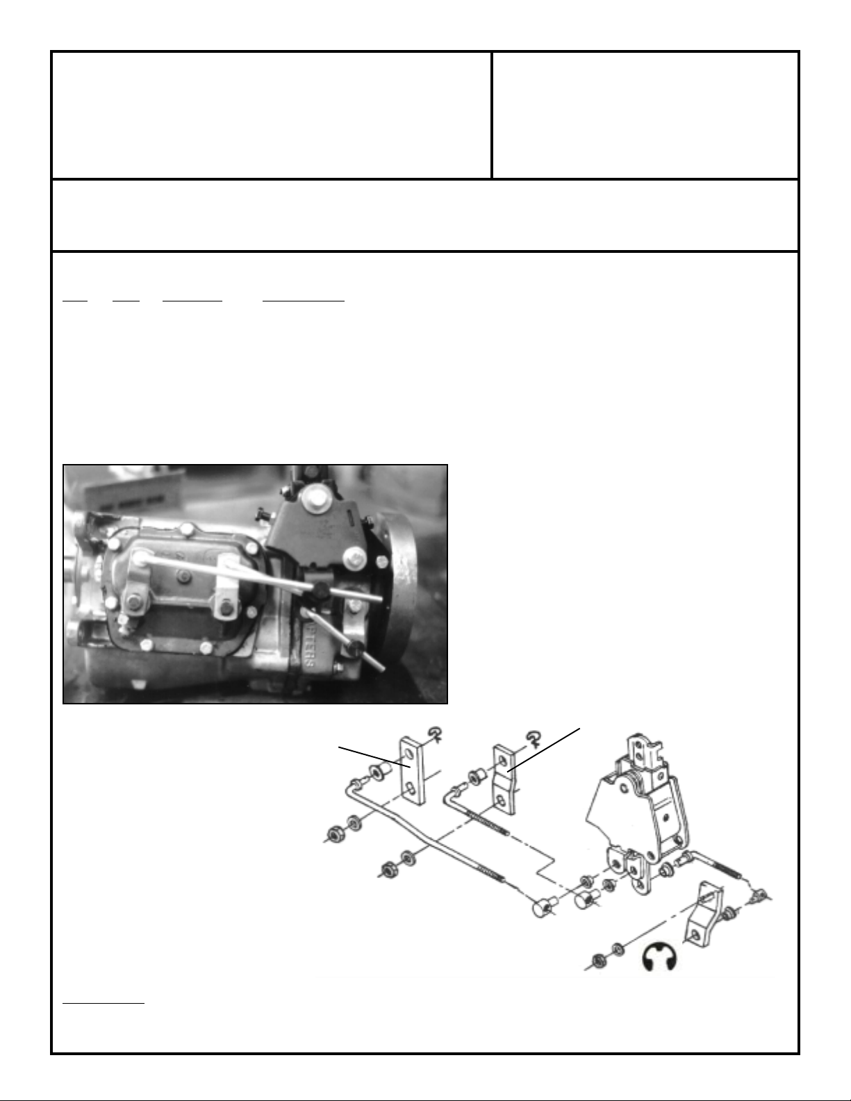
SHIFTER LINKAGE ROD & LEVER KIT
FOR EARLY STYLE MUNCIE 4 SPEEDS
KIT CONSISTS OF:
No. Qty Part No. Description
1. 3 715649 BUTTON
2. 6 715650 NYLON BUSHINGS
3. 6 715651 CLIPS
4. 2 715656 ROD
5. 1 715657 RODS
6. 1 715671 LEVERS
7. 2 715672 LEVER
8. 1 715676 LEVER
9. 3 303115 E-CLIP RETAINER
PART NO.
PART NO.
715672
SPECIAL NOTE: The components packaged in this kit have been assembled and machined for specific type of conversions. Modifications to any of the components will void
any possible warranty or return privileges. If you do not fully understand modifications or changes that will be required to complete your conversion, we strongly recommend that
you contact our sales department for more information. This instruction sheet is only to be used for the assembly of Advance Adapter components. We recommend that a service
manual pertaining to your vehicle be obtained for specific torque values, wiring diagrams and other related equipment. These manuals are normally available at automotive dealerships
and parts stores.
715671
Page 2
ADVANCE ADAPTERS INC. P/N: 715625
P.O. Box 247, 4320 Aerotech Center Way
Paso Robles, CA 93447 PAGE 2 OF 2
Telephone: (800) 350-2223 Fax: (805) 238-4201 Page Rev. Date: 05-07-93
SHIFTER LINKAGE ROD & LEVER KIT
FOR EARLY STYLE MUNCIE 4 SPEEDS
INSTALLATION INSTRUCTIONS:
1. Align levers with shifter frame and insert neutral *alignment rod through notches in frame and holes in levers.
(*Use small bolt or pin to align).
2. Rotate transmission arms backward and forward. The neutral position for each arm can be felt at the mid-position
of full travel. Reverse arm must be moved to the end of its travel toward the front (disengage position).
3. Adjust position of button on each rod to permit easy slip-in fit of button into nylon bushings in proper lever.
Transmission arms must remain in neutral position while aligning is being performed. Fasten buttons in levers with
spring clips.
4. Remove neutral alignment rod. Test shifter. Stick should move freely from side to side at neutral (between 1-2
& 3-4 shifting paths). An increased pull towards the operator should engage the reverse lever.
5. Adjust shifter stop bolts. Back bolts out of shifter frame into 3rd gear and hold. Screw in 3rd gear stop bolt until
contact is felt. Back out bolt one turn and tighten lock nut. Pull stick firmly back into 4th gear, screw in 4th gear
stop bolt until contact is made, then back out stop bolt one turn and tighten lock nut.
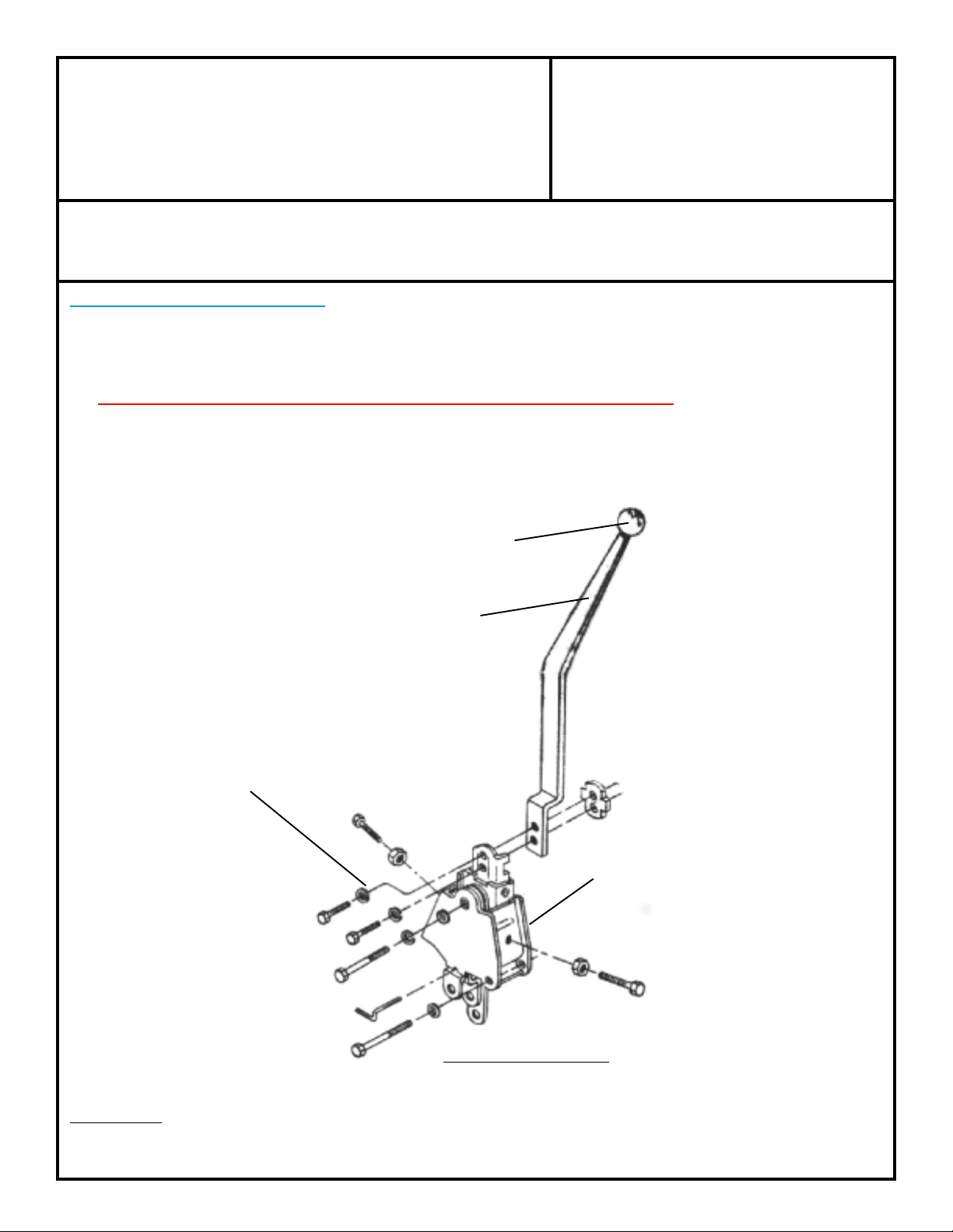
BAGGED HARDWARE
PART NO. 715646
PART NO. 715648
PART NO. 715644
PART NO. 715647
TYPICAL HURST TOWER
PART NO. 715600
SPECIAL NOTE: The components packaged in this kit have been assembled and machined for specific type of conversions. Modifications to any of the components will void
any possible warranty or return privileges. If you do not fully understand modifications or changes that will be required to complete your conversion, we strongly recommend that
you contact our sales department for more information. This instruction sheet is only to be used for the assembly of Advance Adapter components. We recommend that a service
manual pertaining to your vehicle be obtained for specific torque values, wiring diagrams and other related equipment. These manuals are normally available at automotive dealerships
and parts stores.
 Loading...