

Page 1
ADVANCE ADAPTERS INC. P/N: 715573
P.O. Box 247, 4320 Aerotech Center Way New Item: (8/02)
Paso Robles, CA 93447 PAGE 1 OF 5
Telephone: (800) 350-2223 Fax: (805) 238-4201 Page Rev . Date: 03-17-11
TOYOTA L/C TRANSFER CASE TWIN STICK
KIT CONSITS OF:
No: Qty Part No. Description
1. 1 *715575 HIGH LOW PIVOT BLOCK
2. 1 715576 T/C HIGH LOW SHIFTER LEVER
3. 1 *715577 2WD/4WD PIVOT BLOCK
4. 1 715579 PIVOT SHAFT
5. 2 715580 3/8"-24 BALL JOINT (High/Low linkage)
6. 1 715581 5/16"-24 BALL JOINT (Mode shift handle)
7. 1 715582 5/16"-24 MALE HEIM (Mode shaft)
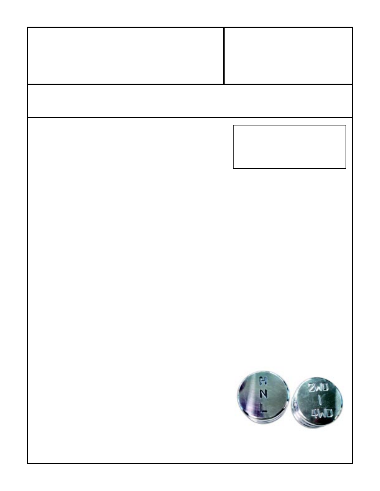
8. 2 715583 SHIFT KNOB
9. 1 715585 TRANSFER CASE MODE SHAFT
10. 1 *715586C HIGH/LOW SHIFT HANDLE (Must be welded to 715575)
11. 1 *715586C MODE SHIFT HANDLE (Must be welded to 715577)
12. 1 *715588C MODE SHIFT LINK (Must be welded to 715577)
13. 1 715589 CLEVIS PIN
14. 1 715590 COTTER PIN
15. 4 **715591 (FJ4404) PIVOT BUSHING
16. 1 723101 5/16"-18 NUT (Pivot pin)
17. 1 723103 5/16" LOCK WASHER
18. 1 723122 5/16" FLAT WASHER (Pivot pin)
19. 1 723131 5/16"-24 JAM NUT (Mode link)
20. 2 723719 3/8"-24 JAM NUT(High/Low link)
21. 1 723769 3/8"-24 SET SCREW (High/Low shift lever)
22. 1 723770 3/8"-24 X 7.5" ALL THREAD (High/Low link)
23. 1 302060 TWIN STICK BOOT
24. 1 302063 BOOT RING
25. 2 303121 1/2"-13 JAM NUT (Shift Knobs)
*ITEMS MUST BE WELDED BEFORE INSTALLING
**ITEMS MUST BE INSTALLED AFTER WELDING
**715591 IS A PRESS FIT INTO THE PIVOT BLOCK
NOTES:
1) GM V8 with a TH350 or 700R transmission
and our T/C adapter.
Note: 4L60E transmissions with the
Mark's adaptor should use P/N 715573B.
We do offer aluminum shifter knobs for
the Toyota twin stick kits. These knobs
are sold separately under Part No. 715584
at a price of $42.95
APPLICATIONS:
This assembly will require the installation of a new mode
shaft into the transfer case. Refer to the exploded assembly
view on the following pages for part identification and part
assembly.
This kit is a universal type kit that requires the handles
to be bent and welded to fit your vehicle.
SPECIAL NOTE: The components packaged in this kit have been assembled and machined for specific type of conversions. Modifications to any of the components will
void any possible warranty or return privileges. If you do not fully understand modifications or changes that will be required to complete your conversion, we strongly recommend
that you contact our sales department for more information. This instruction sheet is only to be used for the assembly of Advance Adapter components. We recommend that a
service manual pertaining to your vehicle be obtained for specific torque values, wiring diagrams and other related equipment. These manuals are normally available at automotive
dealerships and parts stores.
Page 2

ADVANCE ADAPTERS INC. P/N: 715573
P.O. Box 247, 4320 Aerotech Center Way New Item: (8/02)
Paso Robles, CA 93447 PAGE 2 OF 5
Telephone: (800) 350-2223 Fax: (805) 238-4201 Page Rev . Date: 10-04-06
TOYOTA L/C TRANSFER CASE TWIN STICK
INSTALLATION OF PART #715585:
This kit requires the installation of a new mode selector shaft into your stock
transfer case. This shaft can be installed with the transfer case still in the vehicle.
The mode shaft is installed into an aluminum housing that is bolted to the front
output shaft housing of the transfer case. This mode shaft housing bolts on using
(4) 12mm bolts. By removing these bolts, the mode housing can be removed from
the transfer case. Set the mode housing on a bench and remove the plug bolt to
expose the bolt that couples the shift fork to the mode shaft. Remove the shift fork
bolt through this access hole. Remove the
shifter detent ball and spring by removing the
detent bolt. Remove the rubber boot from the
mode housing and pull the mode shaft from the housing. Install the new mode shaft
through the seal and into the housing with the detent notches in the correct orientation.
Reinstall the shift fork bolt into the shift fork and new mode shaft. Insert the detent
ball, spring and cap into the housing. Slide the rubber boot back onto the mode shaft.
Install the mode housing back onto the transfer case, making sure to silicone between
the surfaces to secure for no leaks.
detent ball and spring
715584
shift fork bolt
715587A
715583
715580
(2 PLCS.)
715576
FJ4404
(4 PLCS.)
715579
715585
715582
715581
SPECIAL NOTE: The components packaged in this kit have been assembled and machined for specific type of conversions. Modifications to any of the components will
void any possible warranty or return privileges. If you do not fully understand modifications or changes that will be required to complete your conversion, we strongly recommend
that you contact our sales department for more information. This instruction sheet is only to be used for the assembly of Advance Adapter components. We recommend that a
service manual pertaining to your vehicle be obtained for specific torque values, wiring diagrams and other related equipment. These manuals are normally available at automotive
dealerships and parts stores.
715588
7155876A
715575
715577
Page 3

ADVANCE ADAPTERS INC. P/N: 715573
P.O. Box 247, 4320 Aerotech Center Way New Item: (8/02)
Paso Robles, CA 93447 PAGE 3 OF 5
Telephone: (800) 350-2223 Fax: (805) 238-4201 Page Rev . Date: 09-18-02
TOYOTA L/C TRANSFER CASE TWIN STICK
INSTALLATION
Install the transfer case high/low shifter arm to the top cover of the transfer case. Since Land Cruisers had two shaft
configurations, we have provided two tapped holes on this lever. Match the tapped hole with the flat portion of the shaft.
Temporarily install the pivot shaft and both shift blocks (P/N 715575 & 715577) onto the Advance Adapters bracket. These
two blocks should be pointing straight up at the middle of their range. Paying attention to the orientation of the blocks and
where the stock hole in the floor is located, carefully bend the shift
handles (P/N 715586A) to fit your particular application. Make sure
the handles clear each other as they travel along their path. It may be
necessary at this point to enlarge the hole in the floor to gain clearance
for both handles.
Now weld each handle to its corresponding shift block, as shown.
Mode shift link P/N 715588 comes pre-bent, but the distance it sticks
out of the mode block (P/N 715577) needs to be set for your
application. Weld the mode shift link to the mode block so that it is
in-line with the mode shaft (P/N 715585) and so that the link is parallel
to the long edge of the block (straight down). See pictures “vertical
alignment” and “horizontal alignment" below for a visual description.
Note that the mode shift link may need to be cut on the non-threaded
weld all the way around
end to achieve the desired alignment.
Horizontal alignment with Part No. 715588
Vertical alignment of
Part numbers 715588 & 715587
SPECIAL NOTE: The components packaged in this kit have been assembled and machined for specific type of conversions. Modifications to any of the components will
void any possible warranty or return privileges. If you do not fully understand modifications or changes that will be required to complete your conversion, we strongly recommend
that you contact our sales department for more information. This instruction sheet is only to be used for the assembly of Advance Adapter components. We recommend that a
service manual pertaining to your vehicle be obtained for specific torque values, wiring diagrams and other related equipment. These manuals are normally available at automotive
dealerships and parts stores.
Page 4

ADVANCE ADAPTERS INC. P/N: 715573
P.O. Box 247, 4320 Aerotech Center Way New Item: (8/02)
Paso Robles, CA 93447 PAGE 4 OF 5
Telephone: (800) 350-2223 Fax: (805) 238-4201 Page Rev . Date: 09-18-02
TOYOTA L/C TRANSFER CASE TWIN STICK
After welding is complete, press the bushings (P/N FJ4404) into both shift blocks until they are be completely seated in
both the pivot block holes. This would be the best time to paint the two welded handle assemblies. Make sure to mask
off the bushings (FJ4404) so that no paint gets into the inside diameter. Now assemble the pivot shaft (P/N 715579), both
handles (715586 & 715587), the 5-16" flat washer, the 5/16" lock washer, and the 5/16"-18 nut together as a unit. Push
the handles up through the floor and thread the pivot shaft into the side of the transmission.
Now install the two 3/8" jam nuts and ball joints onto the 3/8" all thread and bolt this assembly to the high/low shift handle
and arm. Adjust the length so that the handle is pointing straight up when the transfer case is in neutral. Cutting of the all
thread may necessary to achieve this. Repeat this same process for the mode shifter assembly using the ball joint, jam nut,
and male heim joint. The male heim joint mounts to the mode shaft with the
supplied clevis pin and cotter pin.
Once the transfer case shifts in a satisfactory manner, mount the shift boot
over the hole in the floor using the metal
ring supplied. Use approximately 4 self
tapping screws to go through the boot,
metal ring, and floor. Finish the installation by adding the 1/2" jam nuts and
the shift knobs.
Twin sticks through modified
hole in floor.
Finished installation
Example of modified/bent handles to fit up through the stock floorboard access hole.
SPECIAL NOTE: The components packaged in this kit have been assembled and machined for specific type of conversions. Modifications to any of the components will
void any possible warranty or return privileges. If you do not fully understand modifications or changes that will be required to complete your conversion, we strongly recommend
that you contact our sales department for more information. This instruction sheet is only to be used for the assembly of Advance Adapter components. We recommend that a
service manual pertaining to your vehicle be obtained for specific torque values, wiring diagrams and other related equipment. These manuals are normally available at automotive
dealerships and parts stores.
Page 5

ADVANCE ADAPTERS INC. P/N: 715573
P.O. Box 247, 4320 Aerotech Center Way New Item: (8/02)
Paso Robles, CA 93447 PAGE 5 OF 5
Telephone: (800) 350-2223 Fax: (805) 238-4201 Page Rev . Date: 09-18-02
TOYOTA L/C TRANSFER CASE TWIN STICK
(Exploded view)
SPECIAL NOTE: The components packaged in this kit have been assembled and machined for specific type of conversions. Modifications to any of the components will
void any possible warranty or return privileges. If you do not fully understand modifications or changes that will be required to complete your conversion, we strongly recommend
that you contact our sales department for more information. This instruction sheet is only to be used for the assembly of Advance Adapter components. We recommend that a
service manual pertaining to your vehicle be obtained for specific torque values, wiring diagrams and other related equipment. These manuals are normally available at automotive
dealerships and parts stores.
 Loading...