

Page 1
ADV ANCE ADAPTERS INC. P/N: 715543-241
P.O. Box 247, 4320 Aerotech Center Way New Item: (10/10)
Paso Robles, CA 93447 PAGE 1 of 8
Telephone: (800) 350-2223 Fax: (805) 238-4201 Page Rev. Date: 07-20-11
TJ 241 CABLE SHIFTER
KIT CONSISTS OF:
Qty Part No. Description
1 303303 SHIFTER BODY BARREL RETAINER
22 303311 HEAT SHIELD-FIREPROOF SLEEVE 1/2"
2 303312 BUSHING- IGUS 3/8"
2 303313 HEIM JOINT- FEMALE 1/4-28
4 303341 BOLT-1/4-28X5/8 BHCS
2 303342 SET SCREW-6-40X3/16 CPSS
2 303343 Access plug
1 303344 Pivot Dowel Pin (Ground) 2.25"””
15" 303345 Sealant - Butyl Tape
1 303346 BOLT-1/4-28X5/8 SHCS
3 340615 Bolt - 1/4-20 X 5/8"” BHCS”
1 722514 NYLON LOCKNUT 1/4-20
1 723753 F.H.C.S. 3/8-161 1/4
3 42R617 BOLT 1/4-20 X 3/8"” BHCS”
1 42R700 Shifter Box- TJ pivot housing
2 42R701 PIVOT PIN MOUNT
1 42R702 BOTTOM COVER
1 42R703 HANDLE MOUNT- DRIVER SIDE
1 42R710 Shift knob - NP241
1 42R707 Lever - T-case NP241
1 42R709 SPRING- WAVE
1 303305 BARREL- CABLE TJ
1 42R725 SHIFTER CABLE- 2"” TRAVEL “
1 42R735 BOLT 1/4-20 X 1"” HHCS”
4 42R745 PLUG 7/16 BLACK
1 715543A CABLE SHIFTER HOUSING CABLE PLUG
1 715543B CABLE SHIFTER HANDLE SPACER
1 715543C TJ CABLE T/C SHIFTER BRKT
1 300474 YOKE SEAL WASHER
1 300476 YOKE NUT
Tool List:
1. FULL SET OF HAND TOOLS INCLUDING:
6 mm ALLEN WRENCH
16 mm DEEP SOCKET
8mm HEX BIT SOCKET
3/8" DRIVE RATCHET
15/16" WRENCH
5/32" ALLEN WRENCH
2. 3/8" TORQUE WRENCH
3. STUBBY 9/16" WRENCH REQUIRED,
RATCHETING RECOMMENDED.
4. #40 TORX BIT
SPECIAL NOTE: The components packaged in this kit have been assembled and machined for specific type of conversions. Modifications to any of the components will
void any possible warranty or return privileges. If you do not fully understand modifications or changes that will be required to complete your conversion, we strongly recommend
that you contact our sales department for more information. This instruction sheet is only to be used for the assembly of Advance Adapter components. We recommend that a
service manual pertaining to your vehicle be obtained for specific torque values, wiring diagrams and other related equipment. These manuals are normally available at automotive
dealerships and parts stores.
Page 2
ADV ANCE ADAPTERS INC. P/N: 715543-241
P.O. Box 247, 4320 Aerotech Center Way New Item: (10/10)
Paso Robles, CA 93447 PAGE 2 of 8
Telephone: (800) 350-2223 Fax: (805) 238-4201 Page Rev. Date: 07-14-11
TJ 241 CABLE SHIFTER
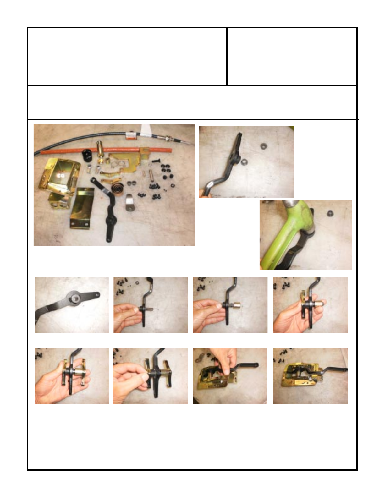
The Igus bushings must be pressed into the shift handle. A arbor press or a light hand
with a hammer works well. Once the bushings are installed the pivot pin gets installed
through the handle.
Install the wave washer and spacer, then the pivot pin mounts.
Once both pivot pin mounts are installed, use the #6 set screws to lock them to the pivot pin. The pivot pin should be
flush with the outside edge of the pin mounts. Install the handle assembly into the shifter housing making sure the handle
is pointing forward or in the same direction as where the cable will be mounted (see photo).
SPECIAL NOTE: The components packaged in this kit have been assembled and machined for specific type of conversions. Modifications to any of the components
will void any possible warranty or return privileges. If you do not fully understand modifications or changes that will be required to complete your conversion, we
strongly recommend that you contact our sales department for more information. This instruction sheet is only to be used for the assembly of Advance Adapter
components. We recommend that a service manual pertaining to your vehicle be obtained for specific torque values, wiring diagrams and other related equipment.
These manuals are normally available at automotive dealerships and parts stores.
Page 3
ADV ANCE ADAPTERS INC. P/N: 715543-241
P.O. Box 247, 4320 Aerotech Center Way New Item: (10/10)
Paso Robles, CA 93447 PAGE 3 of 8
Telephone: (800) 350-2223 Fax: (805) 238-4201 Page Rev. Date: 07-14-11
TJ 241 CABLE SHIFTER
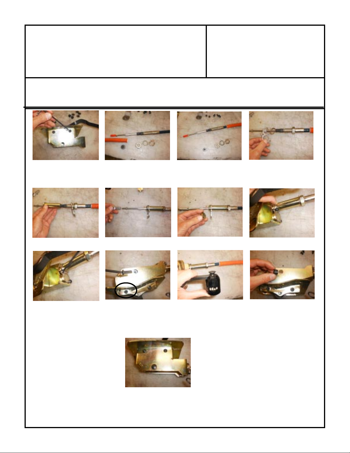
Secure the pivot pin mounts to the shifter housing using 3 of the B.H.C.S and the one S.H.C.S (see 2nd photo on row 3).
Remove the double nuts and star washer from one side of the cable and slip the heat sheild over the cable. One of these
nuts gets discarded and install one of theme back on the cable with the star washer.
Install the cable barrel retainer (make sure it is orientated correctly) and thread the cable barrel on to the cable.
Thread the heim joint to the cable end and before mounting to the shifter housing install the extra cable barrel plug.
Retain the cable assembly to the shifter housing with the 3 B.H.C.S. Line the heim joint with the handle and install the
bolt through the access hole in the shifter. We have provided plugs for these once the fasteners are tight. The shift knob
uses a flat head bolt that recesses into the shifter handle and can be installed now or during assembly into the vehicle.
SPECIAL NOTE: The components packaged in this kit have been assembled and machined for specific type of conversions. Modifications to any of the components
will void any possible warranty or return privileges. If you do not fully understand modifications or changes that will be required to complete your conversion, we
strongly recommend that you contact our sales department for more information. This instruction sheet is only to be used for the assembly of Advance Adapter
components. We recommend that a service manual pertaining to your vehicle be obtained for specific torque values, wiring diagrams and other related equipment.
These manuals are normally available at automotive dealerships and parts stores.
Page 4

ADV ANCE ADAPTERS INC. P/N: 715543-241
P.O. Box 247, 4320 Aerotech Center Way New Item: (10/10)
Paso Robles, CA 93447 PAGE 4 of 8
Telephone: (800) 350-2223 Fax: (805) 238-4201 Page Rev. Date: 10-11-10
TJ 241 CABLE SHIFTER
Disassembly/Preparation For Assembly:
1. Use an Advance Adapters Uni-Raise (PN: 15-
1000) (See Figure 1) or some other device to
support the transmission pan to support its weight.
Take caution to avoid denting the pan and dam-
aging the transmission.
2. Remove the four M10 foot-mount nuts from the
crossmember.
3. Remove crossmember and any aftermarket skid
plates.
4. Remove front drive shafts. The front yoke of the NP241 is also required to be removed to install the new
shift lever. The removal of the yoke is the only way to reach the # 40 torx head and this is has been thread
locked to the transfer case from New Process.
Figure 1: Uni-Raise
Interior Disassembly/Reassembly:
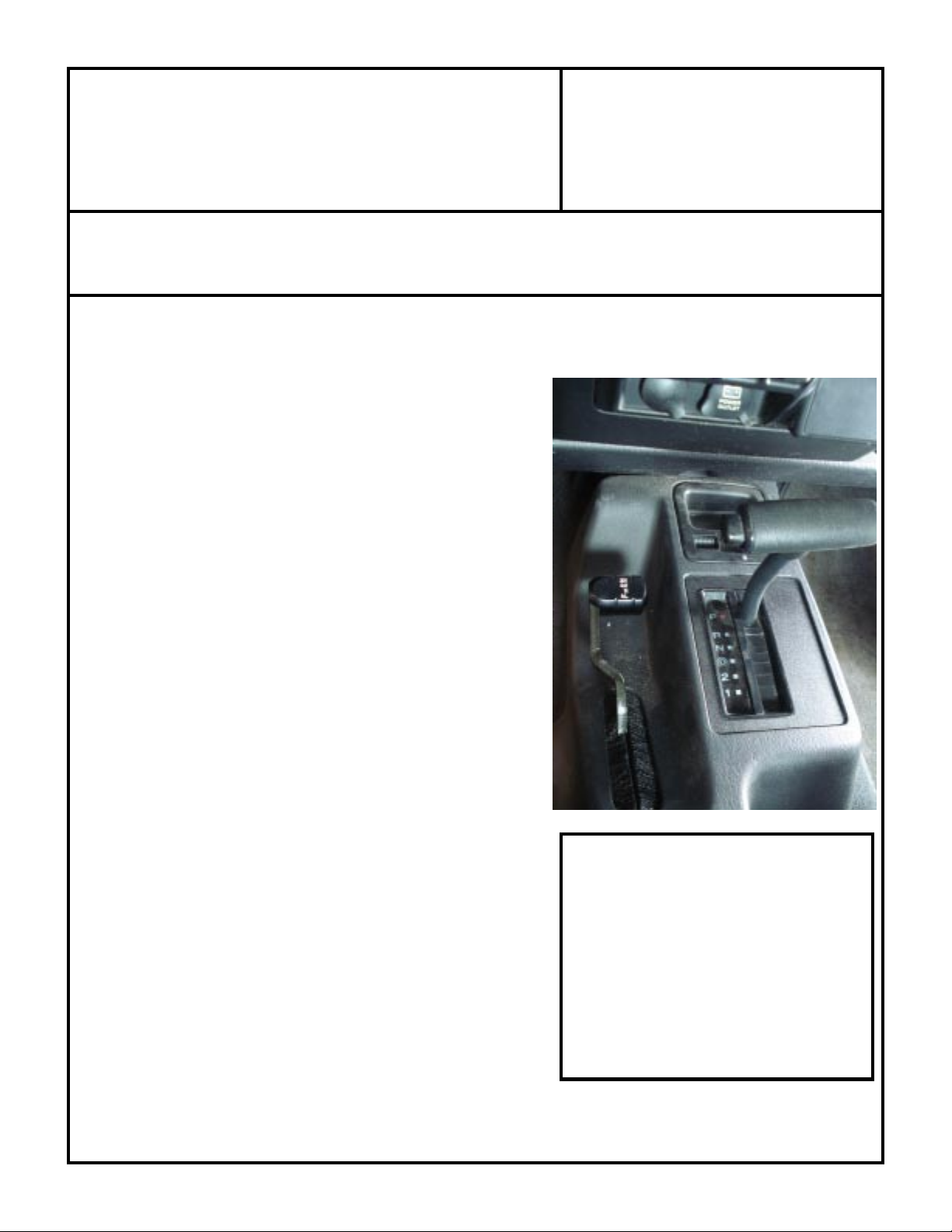
1. Remove the cup holder if it is removable, depending on the
style of your console. (See Figure 8)
2. Remove the transmission shift handle by grabbing firmly and
pulling straight up until it pops off.
3. Using a small flat head screw driver, remove the transmission
shift indicator cover. Once it pops loose you must disconnect
the light on the bottom side of the cover to completely remove
it. (See Figure 9 and 10)
4. Use a 10mm socket to
remove the two console bolts
located under the cup holder and
under the shift indicator panel.
5. Move transfer case
handle to 4wd-Low and then pull
the console out.
Figure 9: Transmission Shift Indicator
SPECIAL NOTE: The components packaged in this kit have been assembled and machined for specific type of conversions. Modifications to any of the components
will void any possible warranty or return privileges. If you do not fully understand modifications or changes that will be required to complete your conversion, we
strongly recommend that you contact our sales department for more information. This instruction sheet is only to be used for the assembly of Advance Adapter
components. We recommend that a service manual pertaining to your vehicle be obtained for specific torque values, wiring diagrams and other related equipment.
These manuals are normally available at automotive dealerships and parts stores.
Figure 8: Cup Holder Removal
Figure 10: Indicator Light
Page 5

ADV ANCE ADAPTERS INC. P/N: 715543-241
P.O. Box 247, 4320 Aerotech Center Way New Item: (10/10)
Paso Robles, CA 93447 PAGE 5 of 8
Telephone: (800) 350-2223 Fax: (805) 238-4201 Page Rev. Date: 10-11-10
TJ 241 CABLE SHIFTER
6. Using a flathead screwdriver, remove the wire loom connector clip
from the transfer case shifter bracket. (See Figure 11)
7. Using an 8mm socket, remove the five transfer case shifter bracket
bolts. Make sure to save these bolts as they will be reused.
8. Using a straight screw driver or a pry bar, pry the linkage rod from
the floor shifter assembly. (fig 11A) Also pry the linkage rod from
the stock transfer case lever.(fig 11B)
Figure 11: Remove Wire
Loom Connector Clip
9. Using a 10 mm socket, remove the four bolts securing the shifter pivot
assembly. (See Figure 12) You will have to lift up the carpet to get to
these bolts. The bracket will fall when the bolts are removed if it isn't held.
Seal the bolt holes with the four supplied black plastic plugs.
Figure 11A
Figure 12: Shifter Pivot
Assembly Bolts
Figure 11B
SPECIAL NOTE: The components packaged in this kit have been assembled and machined for specific type of conversions. Modifications to any of the components
will void any possible warranty or return privileges. If you do not fully understand modifications or changes that will be required to complete your conversion, we
strongly recommend that you contact our sales department for more information. This instruction sheet is only to be used for the assembly of Advance Adapter
components. We recommend that a service manual pertaining to your vehicle be obtained for specific torque values, wiring diagrams and other related equipment.
These manuals are normally available at automotive dealerships and parts stores.
Page 6

ADV ANCE ADAPTERS INC. P/N: 715543-241
P.O. Box 247, 4320 Aerotech Center Way New Item: (10/10)
Paso Robles, CA 93447 PAGE 6 of 8
Telephone: (800) 350-2223 Fax: (805) 238-4201 Page Rev. Date: 10-11-10
TJ 241 CABLE SHIFTER
10. Remove the transfer case shifter and the linkage by lifting
it up and out through the floor. (See Figure 13)
11. Remove linkage assembly and remove the bracket from
the frontof the transfer case. The upper bolt can be
accessed through the shifter hole in the floor board if
needed. (Fig13A & 13B)
12. Take the new shifter housing and apply butyl tape around
the perimeter of the shifter box.
13. With the aid of another person, install the shifter box assembly ensuring that the transfer case cable is
routed under the transmission cooler line.
14. Route the new cable along side the transmission.
15. Bolt the shifter box assembly down using an 8 mm socket and the 5 stock OEM bolts removed prevously.
Figure 13: Remove Shifter Linkage
Figure 13A & B
SPECIAL NOTE: The components packaged in this kit have been assembled and machined for specific type of conversions. Modifications to any of the components
will void any possible warranty or return privileges. If you do not fully understand modifications or changes that will be required to complete your conversion, we
strongly recommend that you contact our sales department for more information. This instruction sheet is only to be used for the assembly of Advance Adapter
components. We recommend that a service manual pertaining to your vehicle be obtained for specific torque values, wiring diagrams and other related equipment.
These manuals are normally available at automotive dealerships and parts stores.
Page 7

ADV ANCE ADAPTERS INC. P/N: 715543-241
P.O. Box 247, 4320 Aerotech Center Way New Item: (10/10)
Paso Robles, CA 93447 PAGE 7 of 8
Telephone: (800) 350-2223 Fax: (805) 238-4201 Page Rev. Date: 10-11-10
TJ 241 CABLE SHIFTER
16. Move the transmission shifter into the "Neutral" position with the new
handle in the vertical position. Point the front of the console towards the
passenger side, then rotate the console counterclockwise as you
maneuver it down over the handle and transmission shifter. Bolt the
console down using a 10mm socket and the two bolts removed earlier.
Install the shift indicator back on to the console making sure to plug in
the indicator bulb before snapping it back in to place. (See Figure 17)
17. Install the new shift knob using the supplied 3/8-16x1-1/4" flat head
cap screw.
Shifter Box Assembly End Cable Adjustment:
1. Rotate the transfer case cable barrel until the center of the knob is 1"
from the console when in its lowest position. (See Figure 21)
2. Tighten the three 1/4-28x5/8" bolts that retain the cable barrel retaining clip.
(See Figure 22)
3. Using a 15/16" wrench, tighten the 5/8" jam nuts on the shift cables.
4. Bolt on the bottom cover of the shifter box using the supplied 1/4-20x3/8"
button head cap screws. NOTE: Make sure you start all 3 before final
tightening. Use RTV for a water tight seal.
Figure 22: Tighten Retaining Clip
Shifter Box Assembly
dash
Passenger Door
Figure 17: Console Install
Figure 21: 1" from console
SPECIAL NOTE: The components packaged in this kit have been assembled and machined for specific type of conversions. Modifications to any of the components
will void any possible warranty or return privileges. If you do not fully understand modifications or changes that will be required to complete your conversion, we
strongly recommend that you contact our sales department for more information. This instruction sheet is only to be used for the assembly of Advance Adapter
components. We recommend that a service manual pertaining to your vehicle be obtained for specific torque values, wiring diagrams and other related equipment.
These manuals are normally available at automotive dealerships and parts stores.
Page 8

ADV ANCE ADAPTERS INC. P/N: 715543-241
P.O. Box 247, 4320 Aerotech Center Way New Item: (10/10)
Paso Robles, CA 93447 PAGE 8 of 8
Telephone: (800) 350-2223 Fax: (805) 238-4201 Page Rev. Date: 10-11-10
TJ 241 CABLE SHIFTER
Transfer Case Installation and Transfer Case Shifter Cable Gear Box End Adjustment:
1. Bolt the transfer case shifter bracket to the front of the transfer case where the stock bracket was bolted.
2. Route the transfer case shifter cable through the transfer case shifter bracket hole with a jam nut on both
sides of the bracket and then completely thread the heim joint on to the end of the cable and tighten the
jam nut. This cable should already be routed under the transmission cooler lines.
3. Remove the tranfer csae shift lever. Note: The transfer case front yoke must be removed. Use an 1-1/8"
socket and impact gun to remove the yoke nut and yoke. Do not allow any contaminants to enter the
transfer case while the yoke is off. Use a long T40 Torx bit and remove the shift lever bolt and then the
shift lever. To reinstall the yoke, install a new rubber yoke washer in to the yoke splines. Apply a bead of
silicone to the inside of the yoke. Apply ATF to the lip of the yoke seal, slide yoke over the rubber washer
until it bottoms out in the case. Secure using the new yoke nut, this is very important as the yoke nuts are
designed for one time use, and torque to 110 ft-lbs. (See Figure 31)
4. Install the new supplied shift lever with the original bolt (use a medium strength thread locking compound
on the threads) and see Figure 30 for correct lever orientation. Torque to 20 ft-lbs.
5. Adjust the transfer case shifter cable by adjusting the two 5/8" nuts so that the heim travels an 1/8" past the
shift lever for both directions of travel.
6. Attach the cable shifter heim to the previously installed shift lever (See Figure30) using the supplied 1/420x1" hex head bolt and a nylock hex nut.
7. Check the position of the lever through the console, adjustments can be made by adjusting the cable
barrels below the shifter box assembly. The transfer case shift lever should change to approximately. 1.25"
from the console after installation and final adjustment.
Barrel Mount
Figure 30: New Transfer Case
Shift Lever Orientation
Figure 31: Proper Yoke
Installation Order
SPECIAL NOTE: The components packaged in this kit have been assembled and machined for specific type of conversions. Modifications to any of the components
will void any possible warranty or return privileges. If you do not fully understand modifications or changes that will be required to complete your conversion, we
strongly recommend that you contact our sales department for more information. This instruction sheet is only to be used for the assembly of Advance Adapter
components. We recommend that a service manual pertaining to your vehicle be obtained for specific torque values, wiring diagrams and other related equipment.
These manuals are normally available at automotive dealerships and parts stores.
 Loading...