

Page 1
ADVANCE ADAPTERS INC. P/N: 713095
P.O. Box 247, 4320 Aerotech Center Way New Item: (11/02)
Paso Robles, CA 93447 PAGE 1 OF 2
Telephone: (800) 350-2223 Fax: (805) 238-4201 Page Rev. Date: 11-27-12
DODGE V8 UNIVERSAL
WELD-IN MOUNTS
KIT CONSISTS OF:
No. Qty Part No. Description
1. 1 713008-NS RUBBER MOUNTS
2. 2 713045 "L" BRACKET
3. 2 713095M BLOCK MOUNTS
4. 4 713094S DRIVER'S SIDE SPACER FOR 360 ENGINES
5. 8 724301 NYLON LOCK NUT 7/16"-14
6. 16 724302 FLAT WASHER 7/16"
7. 4 724308 H.H.C.S. 7/16"-14 x 1-3/4"
8. 4 724309 H.H.C.S. 7/16"-14 x 2"
INSTALLATION PROCEDURES:
This mount kit is designed as a weld-in application. Cutting, grinding, and welding is required.
To install a Dodge V8 into a Jeep CJ or YJ, we recommend that the entire front clip of the vehicle be removed for ease
of installation. This would also include the hood, grille, both fenders, and miscellaneous components. Some of the
components in the engine compartment may need to be relocated (i.e. smog equipment, battery, radiator, overflow, etc.).
Once the stock engine has been removed, you're ready to begin the new engine installation.
Bolt the block mounts to the block using the hardware given. Take note of the thicknesses of each boss and use the
correct length bolt accordingly. Also, one of the bolts may not be used on the block because some Dodge blocks have
only 3 holes on one side.
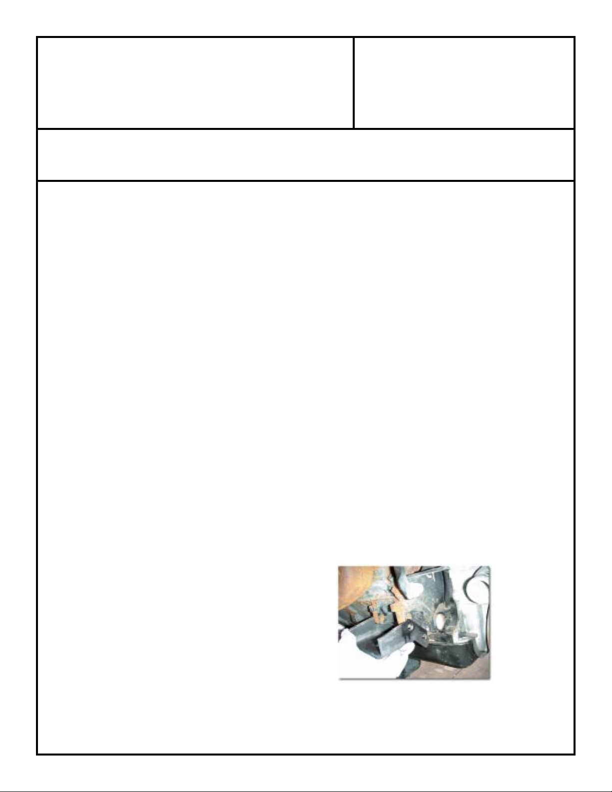
Grind or torch off the stock frame mounts. Grind off all the welds, and make the frame rails smooth. The height and
lateral location of the motor is determined by the placement of the frame brackets. When trial fitting the motor into the chassis
the motor brackets, insulator donuts, and frame brackets should be assembled. Make sure that the dual donut rubber mount
assembly is properly assembled for maximum engine insulation. The final position should take into consideration the following
items.
1. Firewall clearance
2.
Oil pan & harmonic balancer clearance
3. Hood clearance
Radiator & fan allowance
4.
5.
Steering box and/or linkage clearance
6.
Header/exhaust manifold clearance
7. Distributor accessibility
8.
Starter motor clearance on front driveline
SPECIAL NOTE: The components packaged in this kit have been assembled and machined for specific type of conversions. Modifications to any of the components will void
any possible warranty or return privileges. If you do not fully understand modifications or changes that will be required to complete your conversion, we strongly recommend that
you contact our sales department for more information. This instruction sheet is only to be used for the assembly of Advance Adapter components. We recommend that a service
manual pertaining to your vehicle be obtained for specific torque values, wiring diagrams and other related equipment. These manuals are normally available at automotive dealerships
and parts stores.
Page 2
ADVANCE ADAPTERS INC. P/N: 713095
P.O. Box 247, 4320 Aerotech Center Way New Item: (11/02)
Paso Robles, CA 93447 PAGE 2 OF 2
Telephone: (800) 350-2223 Fax: (805) 238-4201 Page Rev. Date: 10-10-08
DODGE V8 UNIVERSAL
WELD-IN MOUNTS
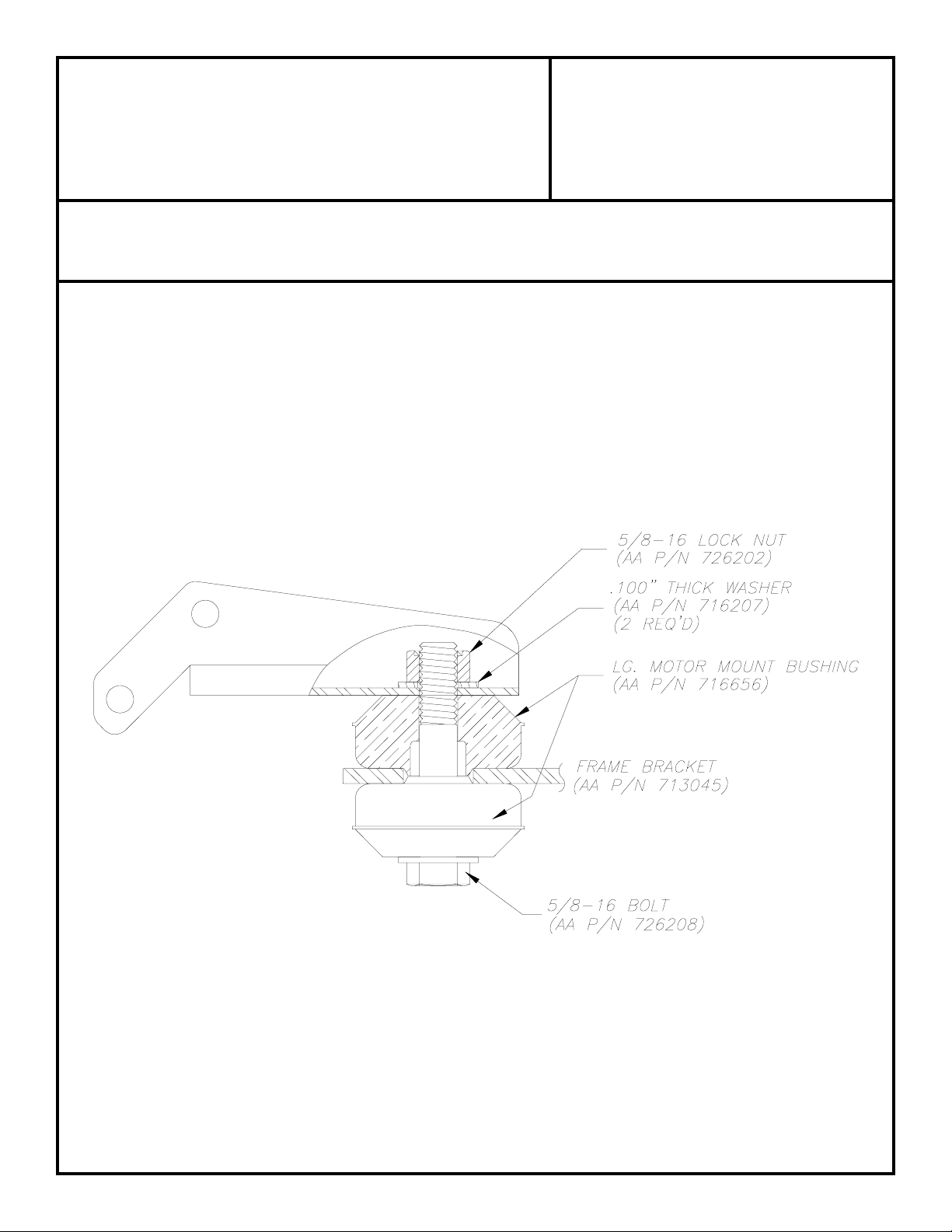
Remove the engine assembly and fully weld the mounts to the frame. Once the frame mounts are welded into position,
the Dodge engine can be reinstalled. We have provided new rubber indexing donuts for isolating the engine vibrations
from the frame and body. These rubber donuts index on the top and bottom of the frame mount. The large 5/8" bolt
is then inserted from the bottom of the frame mount up through the rubber mounts and the block mount. Once the block
is in the correct location and the rubber mounts are installed, tighten the 5/8" locknuts to 25-30 ft./lbs. to secure the
engine location.
DODGE 360 INSTALLATION NOTES:
The Dodge 360 driver's side mount is narrower than that of the Dodge 318. When using this mount on a 360, we have
included four 1/4" spacers. These spacers need to be installed between the block tabs and the block mount. We
recommend using two on the front side of the mount and two on the back side.
SPECIAL NOTE:
Modifications to the engine mount arm brackets may be necessary on certain installations. The mounts may need to be
shortened in order to fit between frame rails. The hole location for the rubber mount position may require a new hole or
slotting between two of the holes.
SPECIAL NOTE: The components packaged in this kit have been assembled and machined for specific type of conversions. Modifications to any of the components will void
any possible warranty or return privileges. If you do not fully understand modifications or changes that will be required to complete your conversion, we strongly recommend that
you contact our sales department for more information. This instruction sheet is only to be used for the assembly of Advance Adapter components. We recommend that a service
manual pertaining to your vehicle be obtained for specific torque values, wiring diagrams and other related equipment. These manuals are normally available at automotive dealerships
and parts stores.
 Loading...