

Page 1
ADVANCE ADAPTERS INC. P/N: 713093
P.O. Box 247, 4320 Aerotech Center Way
Paso Robles, CA 93447 PAGE 1 OF 6
Telephone: (800) 350-2223 Fax: (805) 238-4201 Page Rev . Date: 04-16-14
VORTEC GEN. III V8 SQ. BOLT
TJ WRANGLER MOT OR MOUNTS (WITH A/C)
KIT CONSISTS OF:
No. Qty Part No. Description
1. 2 713092A BOLT SLEEVE
2. 4 713092B GEN 3 MOTOR MOUNT BUSHING
3. 1 713092C GEN 3 MOTOR MOUNT FRAME FIXTURE
4. 1 713092L GEN 3 MOTOR/TJ FRAME MOUNT (Driver’s)
5. 2 713092M GEN 3 ENGINE MOUNT (Right & Left)
6. 1 713092R GEN 3 MOTOR/TJ FRAME MOUNT (Passenger)
7. 4 713092S SPACERS FOR TJ MOUNTS
8. 8 720044 10mm x 1.5mm x 20mm H.H.C.S.
9. 2 723704 3/8” LOCKW ASHER
10. 2 723721 3/8”-16 x 1” H.H.C.S.
11. 2 723735 3/8” FLAT WASHER
12. 4 725003 1/2” FLAT WASHERS
13. 2 725005 1/2”-13 NYLON LOCK NUT
14. 2 725027 1/2”-13 x 5” H.H.C.S.
Option items:
If your replacing a 6 cylinder,
you will need P/N 713093P.
INST ALLA TION INSTRUCTIONS:
The Jeep TJ should have at least 1” of body lift before starting and a minimum of 4” suspension lift with
adjustable bump stops. The suspension lift is mandatory to clearance the A/C compressor. This motor mount is
designed to work with a 1997-2006 4 cylinder steering bracket, Part# 52058855AB (now discontinued from Jeep). If
your replacing a 6 cylinder, you will need this steering bracket. We also make this part under P/N 713093P.
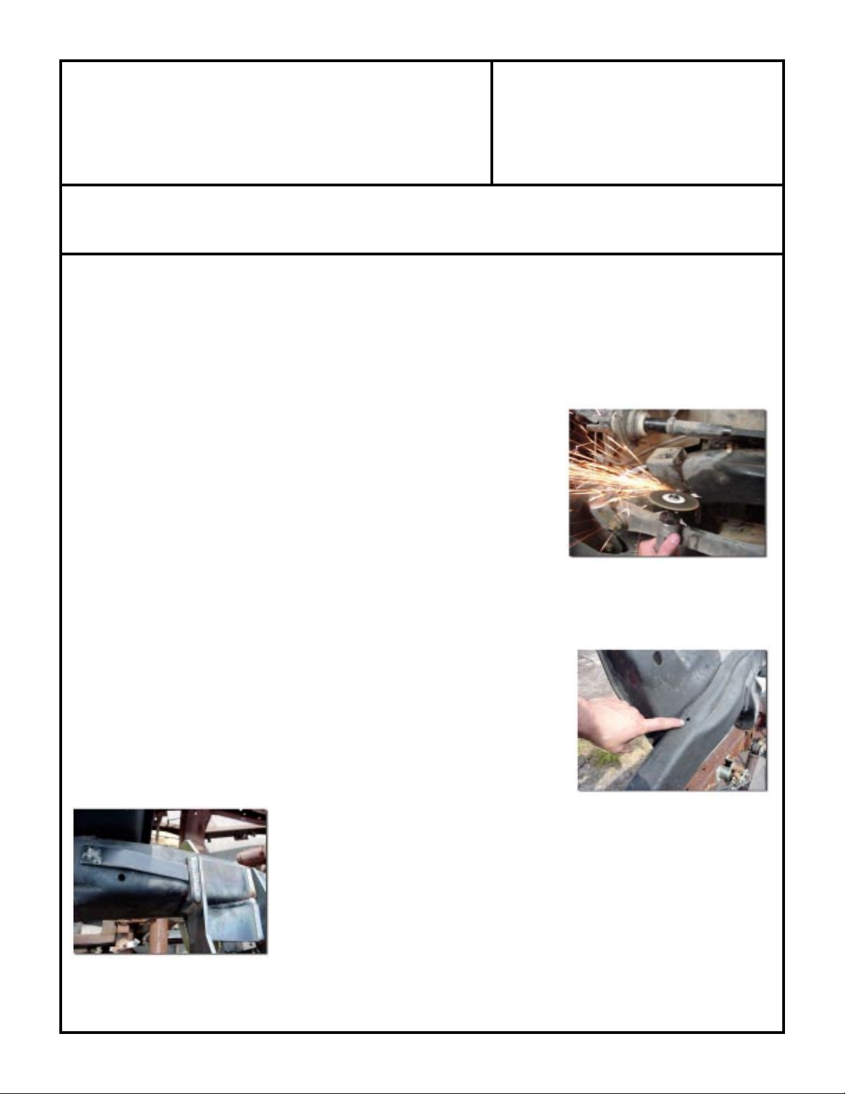
New Mount Installation:
Refer to the owner’s manual for the stock engine removal. Once the stock engine is
removed, cut the original motor mounts from the frame. Also remove the steering
pillow block bracket and discard. Clean all remnants of weld so that the frame is
smooth. Make sure that the frame surface for the mounts is bare metal so that there
are no contaminants in the weld area. The TJ frame has a small hole on both sides that
originally held the brake lines. By removing the brake line mounting bracket you
expose the hole that is used for our fixture bracket. Take the fixture bracket and lay it
on the frame using the 1/4” bolt as a dowel. Lay the new motor mount frame bracket
over the frame and slide it towards the front until it hits the fixture. Clamp or tack
weld the mount to the frame. Do not weld the fixture bracket to the frame. It is only
used to locate the new motor mount. Repeat the clamping and/or welding procedure
for the other side. When both sides are in a fixed position, use a tape measure and
check from the center of the passenger side hole to the center of the driver’s slot.
You should come close to 19.5”. It is also a good idea to check to see if both of the
new frame mounts are located the same distance back on the frame. Next, verify that
the steering pillow block fits to our mount, (6 cylinder Jeeps must purchase the 4
cylinder pillow block listed above or our pillow block 713093P) without any interference. When the mounts have been correctly positioned, weld them in place and paint.
SPECIAL NOTE: The components packaged in this kit have been assembled and machined for specific type of conversions. Modifications to any of the
components will void any possible warranty or return privileges. If you do not fully understand modifications or changes that will be required to complete your conversion,
we strongly recommend that you contact our sales department for more information. This instruction sheet is only to be used for the assembly of Advance Adapter
components. We recommend that a service manual pertaining to your vehicle be obtained for specific torque values, wiring diagrams and other related equipment.
These manuals are normally available at automotive dealerships and parts stores.
Page 2
ADVANCE ADAPTERS INC. P/N: 713093
P.O. Box 247, 4320 Aerotech Center Way
Paso Robles, CA 93447 PAGE 2 OF 6
Telephone: (800) 350-2223 Fax: (805) 238-4201 Page Rev . Date: 08-18-10
VORTEC GEN. III V8 SQ. BOLT
TJ WRANGLER MOTOR MOUNTS (WITH A/C)
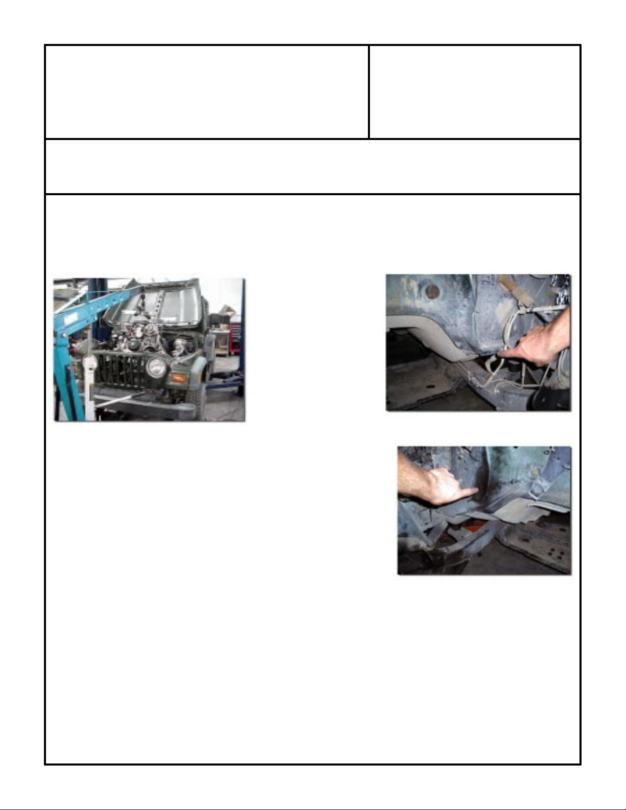
Engine Installation:
* For ease of installation, leave the engine motor mount brackets off until the engine is in place.
* The Vortec engine is very large. Firewall modifications are minor, yet mandatory.
* A trial run is highly recommended.
* The engine and transmission should be bolted together for an easier installation.
Using an approved engine
hoist, lower the engine into
the compartment. Pay attention to the exhaust manifolds
and the radiator (removing
the radiator is a good idea).
The engine may not slide fully
into the compartment due to
firewall interferences (check
the clearance on both the
driver’s and passenger side
around the engine heads and above both of the exhaust manifolds). Mark
these spots with a pen, remove engine, and clearance the firewall accordingly. Lower the engine back in and check the
clearance. Using the supplied hardware, attach the engine mounts to the block.
Take the four large 1/4” spacers (2 per side) and trial fit them to get a comfortable front-to-rear engine placement. These mounts have up to 1/2” movement
front-to-rear to account for any differences in frame locations and to “fine
tune” engine placement. Use the 1/2” bolts and nylon nuts to secure the engine
to the frame. Bolt the steering pillow block assembly to the mount. Take a
quick look around the engine and steering to make sure there are no clearance
issues. You should have just enough room to fit your hand between the engine
and firewall/frame.
Air Conditioning Modifications:
In order to retain air conditioning into the TJ, there are some fairly major modifications that need to be made. The frame
must be modified if the air conditioning compressor is to be used. The configuration of the serpentine belt on the newer
blocks will not allow the compressor bracket to be located anywhere else besides stock. The best way to determine the
proper clearance on the frame would be to do a dry run once the new mounts are in place. It is a good idea to keep the
stock A/C pump lines and manifold handy when checking the clearances. Please keep in mind that it is far easier to make
minor trimming and check often, than it is to repair a frame rail with too much taken out of it. Remove, protect, or reroute anything flammable during this entire procedure. Under a high heat situation, brake fluid will boil, and at that point
SPECIAL NOTE: The components packaged in this kit have been assembled and machined for specific type of conversions. Modifications to any of the
components will void any possible warranty or return privileges. If you do not fully understand modifications or changes that will be required to complete your conversion,
we strongly recommend that you contact our sales department for more information. This instruction sheet is only to be used for the assembly of Advance Adapter
components. We recommend that a service manual pertaining to your vehicle be obtained for specific torque values, wiring diagrams and other related equipment.
These manuals are normally available at automotive dealerships and parts stores.
Page 3

ADVANCE ADAPTERS INC. P/N: 713093
P.O. Box 247, 4320 Aerotech Center Way
Paso Robles, CA 93447 PAGE 3 OF 6
Telephone: (800) 350-2223 Fax: (805) 238-4201 Page Rev . Date: 08-18-10
VORTEC GEN. III V8 SQ. BOLT
TJ WRANGLER MOTOR MOUNTS (WITH A/C)
becomes flammable. This caution applies to both the cutting
and welding portion of this instruction sheet. There are several
ways to remove metal from the frame. An abrasive cut-off
wheel does a great job of keeping the temperature of the cut
down, but it does take more time. A torch is very fast, but
keep an eye on how hot the frame is getting. If you are not
comfortable with the cutting, do not hesitate calling a certified
welder, or simply have it done for you. Keep a fire extinguisher close at hand, and wear all safety equipment.
When you feel comfortable with the notch in the frame, a
piece of scab plate MUST be fit and welded into place on the
frame to bring the frames integrity back. This should be made
out of a minimum of 5/16” plate. Make sure all surfaces are
clean from paint, slag, and any foreign objects. All edges should
meet with a minimal amount of gap between them. Again,
pay attention to the amount of heat you are putting on the
frame. Taking a small break to allow for cooling is a good
idea. TIP: Grinding the surface of a weld for “looks” is not
a bad ideal. ONLY TAKE A MINIMAL AMOUNT OF
MATERIAL OFF! It is very easy to grind too deep and not
even know it. Leaving the entire weld will assure that strength
is not being compromised on the scab plate. When done
correctly , this “clearance notch” should not become a “weak”
point. Please call at any point if there are any questions!
Note that these instructions are based around a truck engine
with truck accessories.
Vacuum Connection for Brake Booster:
You will notice that the Vortec block has no provision for a vacuum line for the brake
booster. There is a small port on the back of the intake manifold
that can be used. First, pull out the black plug on the intake manifold by holding pressure on the gray ring. Once the plug is out,
drill and tap the black plug for a 1/8” pipe thread. Use a 90 degree
1/8” pipe by 3/8” barb adapter and thread it into the tapped plug.
Press the plug back into the manifold and attach the hose.
SPECIAL NOTE: The components packaged in this kit have been assembled and machined for specific type of conversions. Modifications to any of the
components will void any possible warranty or return privileges. If you do not fully understand modifications or changes that will be required to complete your conversion,
we strongly recommend that you contact our sales department for more information. This instruction sheet is only to be used for the assembly of Advance Adapter
components. We recommend that a service manual pertaining to your vehicle be obtained for specific torque values, wiring diagrams and other related equipment.
These manuals are normally available at automotive dealerships and parts stores.
Page 4

ADVANCE ADAPTERS INC. P/N: 713093
P.O. Box 247, 4320 Aerotech Center Way
Paso Robles, CA 93447 PAGE 4 OF 6
Telephone: (800) 350-2223 Fax: (805) 238-4201 Page Rev . Date: 08-18-10
VORTEC GEN. III V8 SQ. BOLT
TJ WRANGLER MOT OR MOUNTS (WITH A/C)
Gauge Wiring:
The Vortec V8 and the Jeep systems do not “speak the same language”. In
our installations, we retained the stock Jeep computer as well as installed
the new Vortec computer. We retained the stock Jeep sending units and
attached them to the GM block (oil pressure, temperature, and fuel level).
All of them work fine except the tachometer. An aftermarket tachometer
would be the easiest option at this point. Since you are using the stock
sending units, the Jeep computer thinks that the original engine is still sending information. The Jeep service manual identifies the color coded wires
in the harness, we retained the ones for the gauges and the other leads that
are not used from the stock Jeep harness were clipped. Before clipping
wires, you should double check with the service manual and determine
what is “not needed”. (Remember: It is easier to cut wires later than to solder them back together). It is possible to run
the Vortec “check engine” light if you wire it behind the dash and replace the stock Jeep light. Removing the dash and
instrument bezel will give you easy access to the engine light. Redline gauges 661-259-8891 does offer a option for
making the factory tach work.
Take care when soldering and striping wires. It is always best to unplug the battery and also disconnect the plugs from
both the Jeep and Vortec computers. It only takes a minimal amount of voltage on the wrong circuit to damage these
computers. Likewise, only approved test probes should be used. Please read and understand all the warnings printed in
both owners manuals. Make sure to secure the Vortec computer in a place that will be free from dirt, water, and physical
damage. Also place all relays and fuse block out of harms way (inside the tub is best).
Power S teering:
The Jeep and the Vortec Gen. III blocks should have matching fittings. In most cases, the stock GM truck pressure line
can be rerouted to work on the Jeep box. The low pressure return line could be any approved oil hose since it sees only
minimal line pressure. The low pressure hose should always be secured with hose clamps. Make sure the hoses have
clearance in the routing to avoid rubbing on anything. Fill the pump reservoir with fluid and replace the cap when all
connections are secure.
Radiator Hoses:
For our conversion we ran to our local auto parts store for hoses. The lower
hose is NAPA P/N 7473. The upper hose is actually two separate hoses spliced
together. A 1/2” hole with pipe thread was tapped into this splice for the stock
TJ temperature sending unit. The two hoses were NAPA P/N 8111 and 8563.
We used our custom Rad-a-Kool radiator for this conversion to make sure cooling would not be an issue. The radiator fit into the stock location on the Jeep TJ.
The Vortec engines recommend a 50/50 mixture of Dex-cool and water.
SPECIAL NOTE: The components packaged in this kit have been assembled and machined for specific type of conversions. Modifications to any of the
components will void any possible warranty or return privileges. If you do not fully understand modifications or changes that will be required to complete your conversion,
we strongly recommend that you contact our sales department for more information. This instruction sheet is only to be used for the assembly of Advance Adapter
components. We recommend that a service manual pertaining to your vehicle be obtained for specific torque values, wiring diagrams and other related equipment.
These manuals are normally available at automotive dealerships and parts stores.
Page 5

ADVANCE ADAPTERS INC. P/N: 713093
P.O. Box 247, 4320 Aerotech Center Way
Paso Robles, CA 93447 PAGE 5 OF 6
Telephone: (800) 350-2223 Fax: (805) 238-4201 Page Rev . Date: 08-18-10
VORTEC GEN. III V8 SQ. BOLT
TJ WRANGLER MOT OR MOUNTS (WITH A/C)
Throttle Linkage:
1999 to 2002 truck Vortec engines are cable operated, to connect the two,
start by drilling a hole in the firewall where the stock Jeep cable was located. The hole diameter is determined by taking a pair of calipers and
measuring the mounting slot on the stock GM throttle linkage. Use the
correct drill bit and open the stock hole on the Jeep firewall. The hole must
be big enough to accept the housing, but not too large for it to slip through.
The inner cable may need some shortening to work correctly with the
stock pedal. It may even be necessary to solder and relocate the stop on
the cable.
Fans:
Either a stock clutch fan or an electric fan will work with these motor mounts. With our aluminum radiator, there should
be approximately 2-1/2” between the clutch on the fan and the radiator fins. A
custom shroud will have to be fabricated if you use the clutch fan.
An electric fan is what we used and it works great with these mounts. There
is ample clearance in the engine compartment which allows for good air circulation. We offer a Spal fan and mounting brackets to fit our radiator under Part
No. 716670. This fan is rated at 2070 CFM. Not all fans are created equal, so
make sure that your electric fan has enough CFM for your setup. Also keep in
mind that a “puller” fan will draw in more air and cools better than a “pusher”
fan.
Exhaust:
All of the stock exhaust system must be removed for the Vortec conversion. New pipe should be run from the manifolds
all the way out. Routing the exhaust around the frame should not be a problem. Weld flanges and crush gaskets are
available separately for the truck-style Vortec manifolds (AA P/N 716573 and P/N 717514). If you are doing a smog legal
conversion, you may need to find a stock GM vehicle to measure the location of where the oxygen sensors and cats are
located on the stock pipes. Also make sure proper heat shielding is used between exhaust components and the floorboard. The recommended size for exhaust is 2-1/2” primaries into 3” tail pipe, or 2-1/2” dual all the way out. For
pollution controlled vehicles, please refer to the owner’s manual for the stock exhaust
configuration. We do not offer any header systems for the Jeep TJ.
Intake:
The intake we used on our TJ installation was a GM 25176891. This ducting was cut
and modified to fit the Jeep configuration. We used a K&N air filter, P/N E-1796. This
setup required a electric fan to be used.
SPECIAL NOTE: The components packaged in this kit have been assembled and machined for specific type of conversions. Modifications to any of the
components will void any possible warranty or return privileges. If you do not fully understand modifications or changes that will be required to complete your conversion,
we strongly recommend that you contact our sales department for more information. This instruction sheet is only to be used for the assembly of Advance Adapter
components. We recommend that a service manual pertaining to your vehicle be obtained for specific torque values, wiring diagrams and other related equipment.
These manuals are normally available at automotive dealerships and parts stores.
Page 6

ADVANCE ADAPTERS INC. P/N: 713093
P.O. Box 247, 4320 Aerotech Center Way
Paso Robles, CA 93447 PAGE:
6 OF 6
Telephone: (800) 350-2223 Fax: (805) 238-4201 Page Rev . Date: 08-18-10
VORTEC GEN. III V8 SQ. BOLT
TJ WRANGLER MOTOR MOUNTS (WITH A/C)
Fuel System:
Refer to the fuel section of your Jeep owner’s manual before servicing or taking apart
any piece of the fuel system. Special fittings, pressurized line, and certain procedures
must be taken into consideration before work can be done on the fuel system. Do not
take short cuts on fuel systems. The new Vortec Gen. III fuel rails have anywhere
between 50-60 pounds of fuel pressure! Only approved high pressure hose and fittings
should be used. T ake care when routing fuel lines, and make sure all fittings are secure.
The new Vortecs need a minimum diameter of 3/8” line on the pressure side, and a
minimum of 5/16” on the return (3/8” is best for the return line). The stock Jeep fuel
pump comes close to feeding the new block, but falls short. The stock Jeep fuel pump
is internally regulated in the fuel tank at 46 psi. The Vortecs regulate at 56 psi on the fuel
rail. Since the Jeep regulated the pressure at the tank, it did not run a return fuel line.
We opted to run two new 3/8” lines, one pressure and one return. The pressure line
needs to be installed by drilling and installing a bulkhead-type “AN” fitting alongside the
stock Jeep pump assembly. A fuel tank pick up must also be installed. Make sure the
new pick up line draws from the bottom of the tank and has no restrictions. The old
Jeep “pressure” line out of the tank can be used as a return line connection from the
Vortec. To use this connection you must take all the “guts” out of the stock internal
regulator. The photos on this page show the modifications we did.
So we basically abandoned the stock Jeep fuel tank pump and used a in-line after market
fuel pump to provide the correct pressure. Note newer GM engines today do not
require a fuel return line, so the information will vary depending on the year of Vortec
engine obtained.
The 2005-06 Jeep TJ and LJ fuel tanks and fuel pumps do offer the correct fuel pressure
and hose size, and are the most recommended for this conversion
SPECIAL NOTE: The components packaged in this kit have been assembled and machined for specific type of conversions. Modifications to any of the
components will void any possible warranty or return privileges. If you do not fully understand modifications or changes that will be required to complete your conversion,
we strongly recommend that you contact our sales department for more information. This instruction sheet is only to be used for the assembly of Advance Adapter
components. We recommend that a service manual pertaining to your vehicle be obtained for specific torque values, wiring diagrams and other related equipment.
These manuals are normally available at automotive dealerships and parts stores.
 Loading...