

Page 1
ADVANCE ADAPTERS INC. P/N: 713015A
P.O. Box 247, 4320 Aerotech Center Way
Paso Robles, CA 93447 PAGE 1 OF 4
Telephone: (800) 350-2223 Fax: (805) 238-4201 Page Rev . Date: 08-10-10
BRONCO II, RANGER 2WD & 1991-94
EXPLORERS TO FORD V8 ENGINE MOUNTS
KIT CONSISTS OF:
No. Qty Part No. Description
1. 1 713015LA LEFT SIDE MOUNT (Driver's side)
2. 1 713015RA RIGHT SIDE MOUNT (long mount)
3. 8 725003 1/2"-13 FLAT WASHERS
4. 2 725004 1/2"-13 HEX NUTS
5. 4 725005 1/2"-13 NYLON LOCK NUT
6. 4 725008 1/2"-13 x 1-1/2" H.H.C.S.
7. 1 FM001 FORD INSTRUCTION MANUAL
OPTIONAL ITEMS:
Qty Part No. Description
1 713017 St ock Engine Mount
1 716412 Oil Pan & Pickup Tube
1 716084 Oil filter relocation kit
1 717044A or
717044A-NP Headers
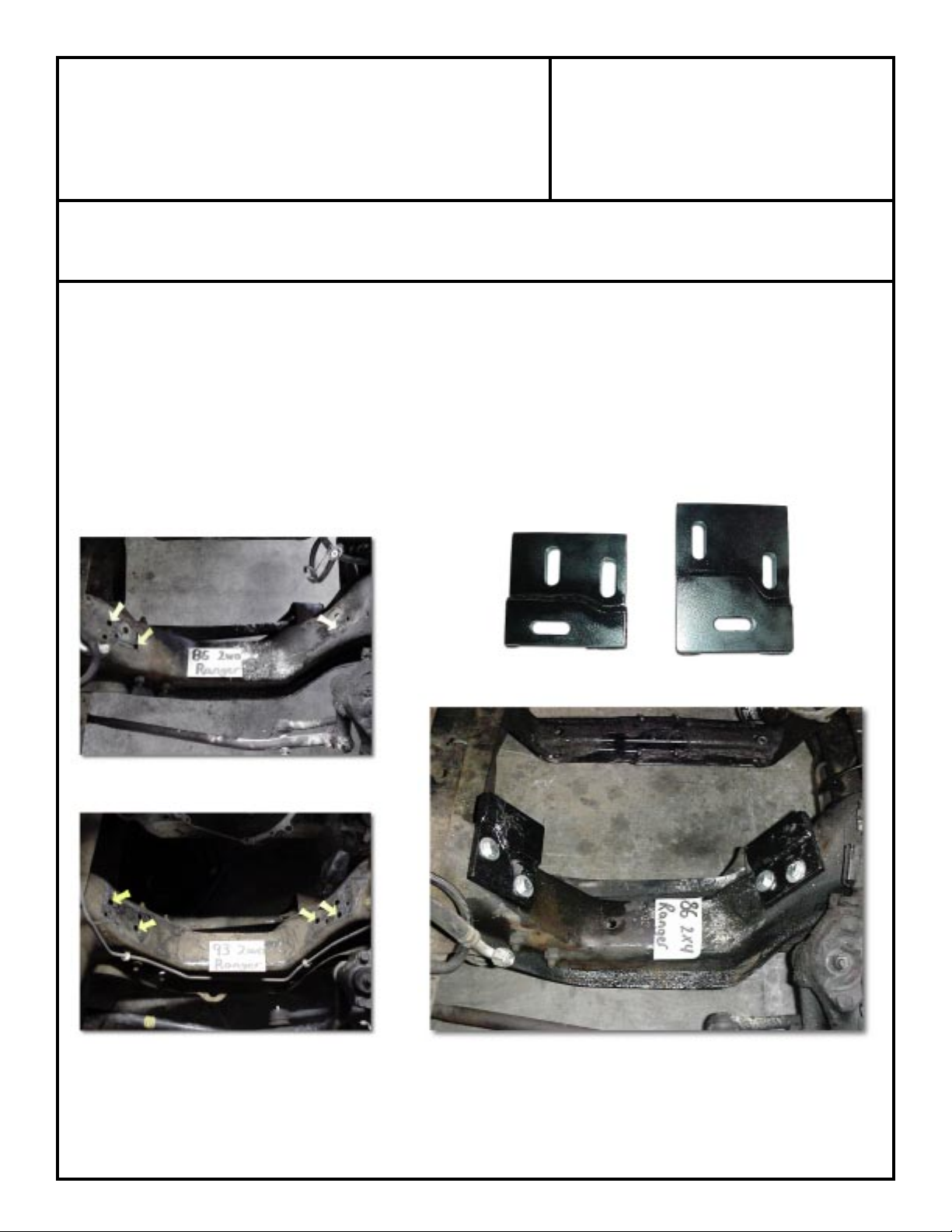
Rangers 1992 & earlier require one hole to be drilled
on the driver's side for the mount to be installed.
The stock holes on 1993 and newer vehicles are used
to mount our mounts.
SPECIAL NOTE: The components packaged in this kit have been assembled and machined for specific type of conversions. Modifications to any of the components will void
any possible warranty or return privileges. If you do not fully understand modifications or changes that will be required to complete your conversion, we strongly recommend that
you contact our sales department for more information. This instruction sheet is only to be used for the assembly of Advance Adapter components. We recommend that a service
manual pertaining to your vehicle be obtained for specific torque values, wiring diagrams and other related equipment. These manuals are normally available at automotive dealerships
and parts stores.
Mounts installed in a Ranger engine cradle
Page 2
ADVANCE ADAPTERS INC. P/N: 713015A
P.O. Box 247, 4320 Aerotech Center Way
Paso Robles, CA 93447 PAGE 2 OF 4
Telephone: (800) 350-2223 Fax: (805) 238-4201 Page Rev . Date: 10-19-01
BRONCO II & RANGER 2WD
FORD V8 ENGINE MOUNTS
REMOVAL PROCEDURES:
Remove the stock engine and transmission. Refer to the owners or service manual for removal instructions. The components
that you will need to remove or disconnect are:
Battery, Intake ducting, Brake booster hose, Exhaust pipe, radiator, Heater hose, Fuel line, A/C lines, Motor mounts,
Transmission mount, Transmission, Engine, A/C condenser, Transmission crossmember, and main wiring harness (from
underneath the fuse box on fender)
GENERAL INSTRUCTIONS:
These mounts are designed to fit both body styles of the Ford Ranger 2WD pickups. The mounts are slotted to have some
adjustment to the engine position once installed. On the early body style Ranger, the driver's side mount will require a hole to
be drilled in the cradle. Accounting for just a couple of differences, the installation of these mounts into both the early and late
model Rangers are basically the same.
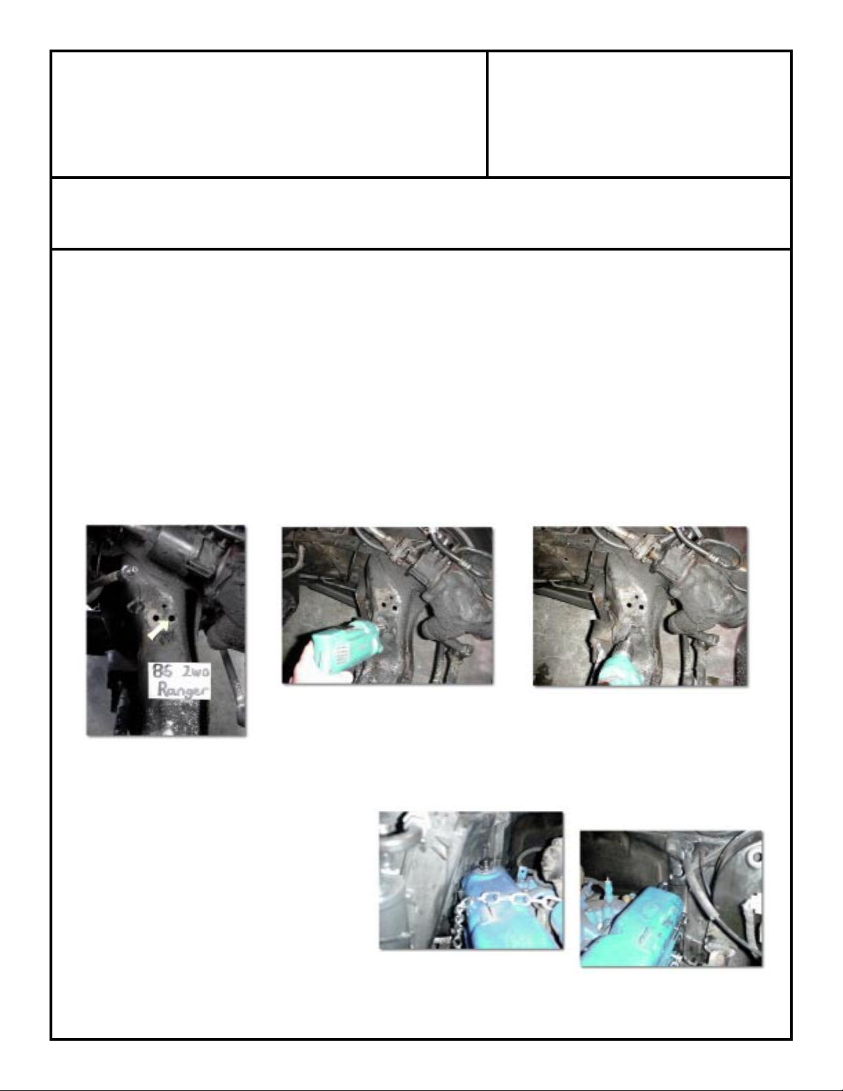
Rangers 1992 & earlier require a hole to be drilled into the stock engine cradle. The way to mark or find the location to drill
is fairly simple. Take the driver's side mount (short mount) and install it to the cradle using the top hole to locate the mount
(
see photos below). Align the mount so that the top or bottom of the mount is parallel with the ground. Mark the cradle using
our lower hole in the mount as a guide. Take a center punch to the center of the hole, mark it and drill with a 1/2" drill.
The 1992 & earlier Rangers also require the fuel filter to be relocated. The fuel filter is located
inside the driver's side frame rail. The fuel filter must be relocated to allow for proper exhaust
clearance.
On both body styles of the Rangers, we recommend doing a "dry run" on the engine installation. The mounts should be installed
loosely into the Ranger engine cradle. Lower the block into position on top of the new mounts and adjust the block to the furthest
forward location allowed by the slots in the mounts.
Adjust the block so that it sets level from side to side.
This first trial run will allow you to mark the air box on
the passenger side of the vehicle for proper clearance.
The driver's side firewall will also require a slight
amount of clearance (a small dent in the fire wall to
obtain valve cover and head clearance). Remove the
engine and perform the necessary modifications to air
box and the firewall.
Passenger side valve cover
SPECIAL NOTE: The components packaged in this kit have been assembled and machined for specific type of conversions. Modifications to any of the components
will void any possible warranty or return privileges. If you do not fully understand modifications or changes that will be required to complete your conversion, we strongly
recommend that you contact our sales department for more information. This instruction sheet is only to be used for the assembly of Advance Adapter components.
We recommend that a service manual pertaining to your vehicle be obtained for specific torque values, wiring diagrams and other related equipment. These manuals
are normally available at automotive dealerships and parts stores.
Driver's side valve cover
Page 3

ADVANCE ADAPTERS INC. P/N: 713015A
P.O. Box 247, 4320 Aerotech Center Way
Paso Robles, CA 93447 PAGE 3 OF 4
Telephone: (800) 350-2223 Fax: (805) 238-4201 Page Rev . Date: 10-29-01
BRONCO II & RANGER 2WD
FORD V8 ENGINE MOUNTS
These mounts are designed to work with both exhaust headers and or stock manifolds. There are two styles of manifolds
that fit these vehicles. The Ford Explorer manifolds fit well and provide the correct emission controls for smog in most vehicles.
For vehicles not concerned about smog, the photos below show stock cast iron Ford manifolds that also fit well; however,
the vehicles that these stock Ford manifolds were off of is not known. If you would rather have an exhaust header, we also
manufacture a header to fit into Ford Rangers. Part number 717044A and 717044A-NP are custom headers designed for our
mounting system. When installing a V8 with our headers, the passenger side header is a tight fit. We recommend that you
set the passenger header alongside the frame rail before setting the engine into the engine compartment. The driver's side header
can be installed once the engine is in the proper location. Once the engine is installed and leveled, bolt both headers to the block
and check clearances.
After the exhaust system is bolted to the block and you've check for clearances on the block and exhaust, secure the motor
mounts to the cradle.
Stock Ford Explorer V8 manifolds for most smog controlled vehicles.Early stock Ford manifolds that fit with our motor mounts.
Side view of the early Ford manifolds. Advance Adapters conversion headers for the 2WD Ford Ranger
SPECIAL NOTE: The components packaged in this kit have been assembled and machined for specific type of conversions. Modifications to any of the components will void
any possible warranty or return privileges. If you do not fully understand modifications or changes that will be required to complete your conversion, we strongly recommend that
you contact our sales department for more information. This instruction sheet is only to be used for the assembly of Advance Adapter components. We recommend that a service
manual pertaining to your vehicle be obtained for specific torque values, wiring diagrams and other related equipment. These manuals are normally available at automotive dealerships
and parts stores.
Page 4

ADVANCE ADAPTERS INC. P/N: 713015A
P.O. Box 247, 4320 Aerotech Center Way
Paso Robles, CA 93447 PAGE 4 OF 4
Telephone: (800) 350-2223 Fax: (805) 238-4201 Page Rev . Date: 10-19-01
BRONCO II & RANGER 2WD
FORD V8 ENGINE MOUNTS
The photo above and photo left show the radiator and fan clearance.
The photo above shows the driver's side firewall modifications.
The photo left shows the air duct modifications for valve cover
clearance on the passenger side.
SPECIAL NOTE: The components packaged in this kit have been assembled and machined for specific type of conversions. Modifications to any of the components will void
any possible warranty or return privileges. If you do not fully understand modifications or changes that will be required to complete your conversion, we strongly recommend that
you contact our sales department for more information. This instruction sheet is only to be used for the assembly of Advance Adapter components. We recommend that a service
manual pertaining to your vehicle be obtained for specific torque values, wiring diagrams and other related equipment. These manuals are normally available at automotive dealerships
and parts stores.
 Loading...