

Page 1
ADVANCE ADAPTERS INC. P/N: 713005
P.O. Box 247, 4320 Aerotech Center Way
Paso Robles, CA 93447 PAGE 1 OF 2
Telephone: (800) 350-2223 Fax: (805) 238-4201 Page Rev. Date: 07-14-10
CHEVY LT1 ENGINE MOUNTS
KIT CONSISTS OF:
No. Qty Part No. Description
1. 1 713008-NS MOUNTING HARDWARE KIT
2. 1 713043 LONG SIDE BLOCK MOUNT
3. 1 713044 SHORT SIDE BLOCK MOUNT
4. 2 713045 FRAME BRACKETS
5. 1 713053 A/C PUMP FOR LT1 BLOCK
6. 1 723798 ENGINE MOUNTING HARDWARE PACKAGE
7. 1 B G BUYER'S GUIDE
These Universal engine mounts are designed for use on all types of 4WD and 2WD vehicles that have frame rail widths
up to 28". The frame brackets can be used in either the upward or downward position for best engine location. The
bracket can be either welded or bolted into position. If you are dealing with a vehicle that has an open channel, then
you should box in the frame rail prior to mounting the new bracket.
Several holes have been stamped in each motor bracket to allow the engine to be offset or centered in the frame rail. On
Jeeps up to 1986 and Toyota conversions, it is best to offset the engine 1" towards the driver's side. Jeep YJ's can be
centered or offset 1" to the passengers side.
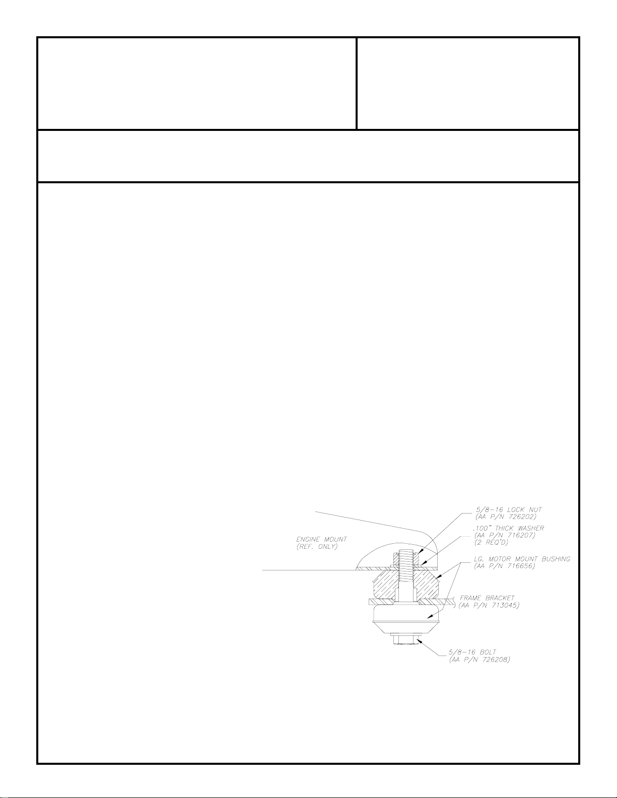
The height and lateral location of the motor is determined by the placement of the frame brackets. When trial fitting the
motor into the chassis assembly, the motor brackets insulator donuts and frame brackets should be assembled. Make
sure that the dual donut rubber mount assembly is properly assembled for maximum engine insulation. The final position
should take into consideration the following items
1. Firewall clearance.
2. Oil pan & harmonic balancer clearance.
3. Hood clearance.
4. Radiator & fan allowance.
5. Steering box and/or linkage clearance.
6. Header/exhaust manifold clearance.
7. Distributor accessibility.
8. Starter motor clearance on front driveline.
THE 5/8"-18 NYLON NUT SHOULD BE
TORQUED TO 25 TO 30 FT./LBS.
SPECIAL NOTE:
Modifications to the engine mount arm brackets may be necessary
on certain installations. The mounts may need to be shortened in
order to fit between frame rails. The hole location for the rubber
mount position may require a new hole or slotting between two of
the holes. These mounts are used on over 50 various applications
and modifications as to length and hole positions are common.
SPECIAL NOTE: The components packaged in this kit have been assembled and machined for specific type of conversions. Modifications to any of the components will void
any possible warranty or return privileges. If you do not fully understand modifications or changes that will be required to complete your conversion, we strongly recommend that
you contact our sales department for more information. This instruction sheet is only to be used for the assembly of Advance Adapter components. We recommend that a service
manual pertaining to your vehicle be obtained for specific torque values, wiring diagrams and other related equipment. These manuals are normally available at automotive dealerships
and parts stores.
Page 2
ADVANCE ADAPTERS INC. P/N: 713005
P.O. Box 247, 4320 Aerotech Center Way
Paso Robles, CA 93447 PAGE 2 OF 2
Telephone: (800) 350-2223 Fax: (805) 238-4201 Page Rev. Date: 09-25-01
CHEVY LT1 ENGINE MOUNTS
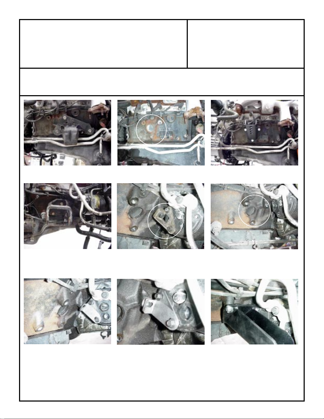
The stock driver's side mount must be removed. The LT1 block has the standard Chevy 3 bolt hole that our conversion
mounts bolt to.
The stock passenger side mount must be removed. The passengers side LT1 mount used an inverted triangular mount;
however, this block also had the standard Chevy mount configuration. The top front hole of the standard mount on
this block was used as a support for the air conditioning pump (shown center photo).
A new bracket has been provided to retain this rear mounting. Mount the new bracket to the air conditioning pump as
shown, slip the motor mount between this new air conditioning pump support and the block. Secure the mount and
air conditioning pump support to the block with the bolts provided. If you are not planning to retain the A/C and would
like to omit this pump, GM offers a bracket and pulley assembly to replace this pump, GM # 10115875.
SPECIAL NOTE: The components packaged in this kit have been assembled and machined for specific type of conversions. Modifications to any of the components will void
any possible warranty or return privileges. If you do not fully understand modifications or changes that will be required to complete your conversion, we strongly recommend that
you contact our sales department for more information. This instruction sheet is only to be used for the assembly of Advance Adapter components. We recommend that a service
manual pertaining to your vehicle be obtained for specific torque values, wiring diagrams and other related equipment. These manuals are normally available at automotive dealerships
and parts stores.
 Loading...