

Page 1

ADVANCE ADAPTERS INC. P/N: 50-9205
P.O. Box 247, 4320 Aerotech Center Way New Kit: (07/06)
Paso Robles, CA 93447 PAGE 1 OF 2
Telephone: (800) 350-2223 Fax: (805) 238-4201 Page Rev. Date: 07-23-06
POWERGLIDE TRANSMISSION TO
DANA 300 TRANSFER CASE
KIT CONSISTS OF:
No. Qty Part No. Description
1. 1 51-8603 ADAPTER CASTING
2. 1 51-9200 ADAPTER HOUSING
3. 1 52-6309 DANA 300 INPUT SHAFT
4. 1 KI T 716055 CRO SSMEMBER MOUNT KIT
5. 1 716308 BEARING (#6209)
6. 1 716511 O-RING
7. 1 716749 NATIONAL SEAL 471870
8. 5 723701 3/8"-16 NUT
9. 5 723714 3/8"-16 x 1.5" STUD
10. 6 723731 S.H.C.S. 3/8"-16 x 1"
11. 6 302069 STUD 3/8"-16 x 3/8"24
12. 6 302071 3/8"-24 FLANGED NUT
13. 5 911003 3/8" STAR WASHER
NOTE:
shaft is 27 splines. We do not sell this shorty output shaft. The shorty output shaft must be installed into your
transmission before you begin with the directions below. Other company output shafts may also work with this
kit, but it is the customer's responsibility to verify shaft length & spline engagement. This adapter kit is 3.07" long.
INSTRUCTIONS:
1. Thread the 3/8"-16 x 1.5" studs into rear of transmission with blue Loctite.
This kit was designed around the Hughes Performance "shorty length" output shaft. The Hughes output
2. Place the Powerglide rear pump gasket into rear of transmission (this gasket comes in the Powerglide rebuild
kit or gasket set).
3. Slide adapter and o-ring over studs, sandwiching the rear pump gasket against the case.
4. Using star washers, 3/8"-16 nuts, and blue Loctite, torque the nut to the adapter approximately 30 ft./lbs.
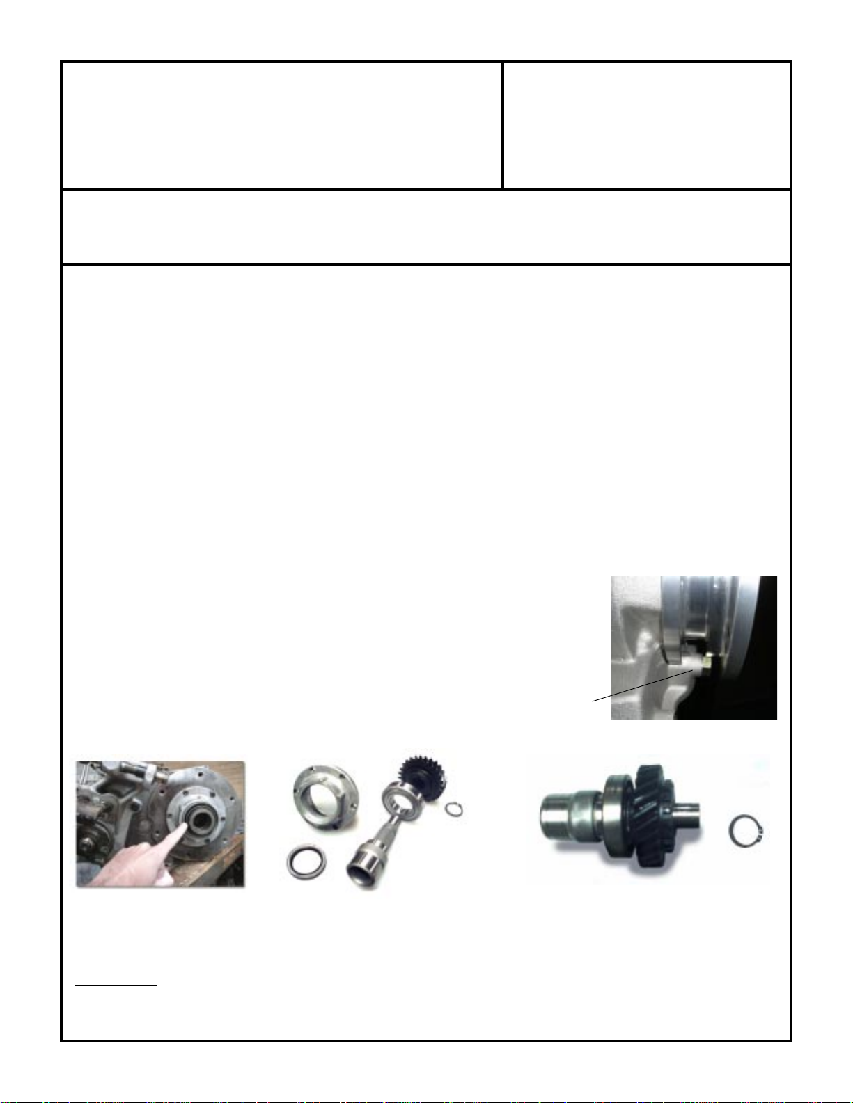
5. Starting at the Dana 300 transfer case, remove the 6 socket head bolts from the aluminum index hub on the front
side the transfer case.
6. Using the two slots on the side of this retainer, you will need to pry the retainer out of the transfer case. This retainer
assembly does pilot into the rear output shaft of this transfer case. If the retainer assembly seams tight to remove,
try spinning the rear output shaft.
7. Once the retainer is removed you will need a pair of snap ring pliers to remove the snap ring that retains the drive
gear to the input shaft. Remove the snap ring and the drive gear from the input shaft. The aluminum retainer should
now have the bearing, input shaft, seal, and a snap ring holding the bearing into the retainer. This snap ring must
also be removed to allow the bearing and input shaft to be pressed out of the index housing.
8. The seal will also be required to be pressed out of the index retainer. The retainer should now be empty.
9. Install the new bearing onto the new input shaft. Install both components into the stock retainer and install the stock
snap ring.
SPECIAL NOTE: The components packaged in this kit have been assembled and machined for specific type of conversions. Modifications to any of the components
will void any possible warranty or return privileges. If you do not fully understand modifications or changes that will be required to complete your conversion, we strongly
recommend that you contact our sales department for more information. This instruction sheet is only to be used for the assembly of Advance Adapter components. We
recommend that a service manual pertaining to your vehicle be obtained for specific torque values, wiring diagrams and other related equipment. These manuals are normally
available at automotive dealerships and parts stores.
Page 2
ADVANCE ADAPTERS INC. P/N: 50-9205
P.O. Box 247, 4320 Aerotech Center Way New Kit: (07/06)
Paso Robles, CA 93447 PAGE 2 OF 2
Telephone: (800) 350-2223 Fax: (805) 238-4201 Page Rev. Date: 07-23-06
POWERGLIDE TRANSMISSION TO
DANA 300 TRANSFER CASE
10. Install the input drive gear onto the input shaft and retain it with the stock snap ring. Make sure the gear is installed
so that the cogged side of the gear is facing away from the bearing.
11. Install the new seal provided in the kit - the open side towards the transmission.
12. Apply Loctite 515 or equivalent sealant to the retainer surface and install into the Dana 300 transfer case. Make
sure the pocket bearing is installed in the Dana 300 output shaft
13. Bolt retainer to the transfer case using the stock bolts. Torque to 10 ft./lbs.
14.
The adapter plate must be rotated to line up the 6 counter sunk holes to the Dana 300. Use a gasket or RTV blue silicone
between these two components. Fasten the S.H.C.S. bolts with Loctite, securing the plate to the transfer case.
15. Once you decide on the rotation and check for front yoke clearance, install the six studs into the adapter ring (these
studs are a tight fit into the ring). Use a gasket or RTV blue silicone and fasten the transfer case to the transmission
adapter plate.
16. The transfer case should be test-fitted to the adapter to check for shaft engagement. Make sure the transfer case
fits flush up to the adapter surface. If not, check for burrs on the shafts and/or output shaft cut off length. Never
pull the transfer case to the adapter using the bolts to draw these components together. The adapter also
provides an option of four rotation angles for the transfer case (stock rotation is 35 degrees).
17. Position the crossmember mount around the adapter.
18. Install the nuts onto the new stud bolts and Loctite to secure.
(illustrated in photo right)
.
If for any reason the two bolt surfaces do not slide together, DO NOT FORCE OR
PULL TOGETHER with the bolts. If you have any questions, please call 800-350-2223,
for technical assistance.
NOTE: Our adapter is clearanced for a Dedednbear Powerglide transmission
case. When using this case, a Dedenbear non-adjustable trans brake bolt must be
used.
AA shaft & bearing with stock parts
SPECIAL NOTE: The components packaged in this kit have been assembled and machined for specific type of conversions. Modifications to any of the components
will void any possible warranty or return privileges. If you do not fully understand modifications or changes that will be required to complete your conversion, we strongly
recommend that you contact our sales department for more information. This instruction sheet is only to be used for the assembly of Advance Adapter components. We
recommend that a service manual pertaining to your vehicle be obtained for specific torque values, wiring diagrams and other related equipment. These manuals are normally
available at automotive dealerships and parts stores.
New input shaft & stock parts assembled.
 Loading...