

Page 1
ADVANCE ADAPTERS INC. P/N: 50-9000
P.O. Box 247, 4320 Aerotech Center Way New Item: (9/09)
Paso Robles, CA 93447 PAGE
Telephone: (800) 350-2223 Fax: (805) 238-4201 Page Rev . Date:
1 OF 6
03-25-10
LAND ROVER SERIES T-CASE to NP
CIRCULAR 6 ADAPTER with JEEP 23 SPLINE
KIT CONSISTS OF:
No. Qty Part No. Description
1. 1 51-9000 ADAPTER PLATE
2. 1 52-9000 SPUD SHAFT 23 SPLINE
3. 1 716064 SHIM
4. 1 716064B LOCK WASHER
5. 1 716239 THRUST WASHER
6. 1 716302 SEALED BEARING
7. 1 716310 SEALED BEARING
8. 1 716762 SEAL
9. 1 300922 90 DEGREE BARBED FITTING
10. 6 302069 STUD BOLT 2-3/16" OAL 3/8-16,24
11. 6 302071 FLANGE NUT 3/8-24 PLATED
12. 2 340031 DOWEL PIN
13. 2 723103 LOCK WASHER 5/16" PLATED
14. 2 723118 H.H.C.S. 5/16"-18x1-3/4" LG
15. 2 723101 NUT 5/16"-18 PLATED
16. 6 723704 LOCK WASHER 3/8" PLATED
17. 6 723723 H.H.C.S. 3/8"-16x1-1/2"
18. 1 728701 NYLON LOCK NUT
SPECIAL NOTE: The components packaged in this kit have been assembled and machined for specific type of conversions. Modifications to any of the components will
void any possible warranty or return privileges. If you do not fully understand modifications or changes that will be required to complete your conversion, we strongly recommend
that you contact our sales department for more information. This instruction sheet is only to be used for the assembly of Advance Adapter components. We recommend that a
service manual pertaining to your vehicle be obtained for specific torque values, wiring diagrams and other related equipment. These manuals are normally available at automotive
dealerships and parts stores.
Page 2
ADVANCE ADAPTERS INC. P/N: 50-9000
P.O. Box 247, 4320 Aerotech Center Way New Item: (9/09)
Paso Robles, CA 93447 PAGE
Telephone: (800) 350-2223 Fax: (805) 238-4201 Page Rev . Date:
2 OF 6
03-25-10
LAND ROVER SERIES T-CASE to NP
CIRCULAR 6 ADAPTER with JEEP 23 SPLINE
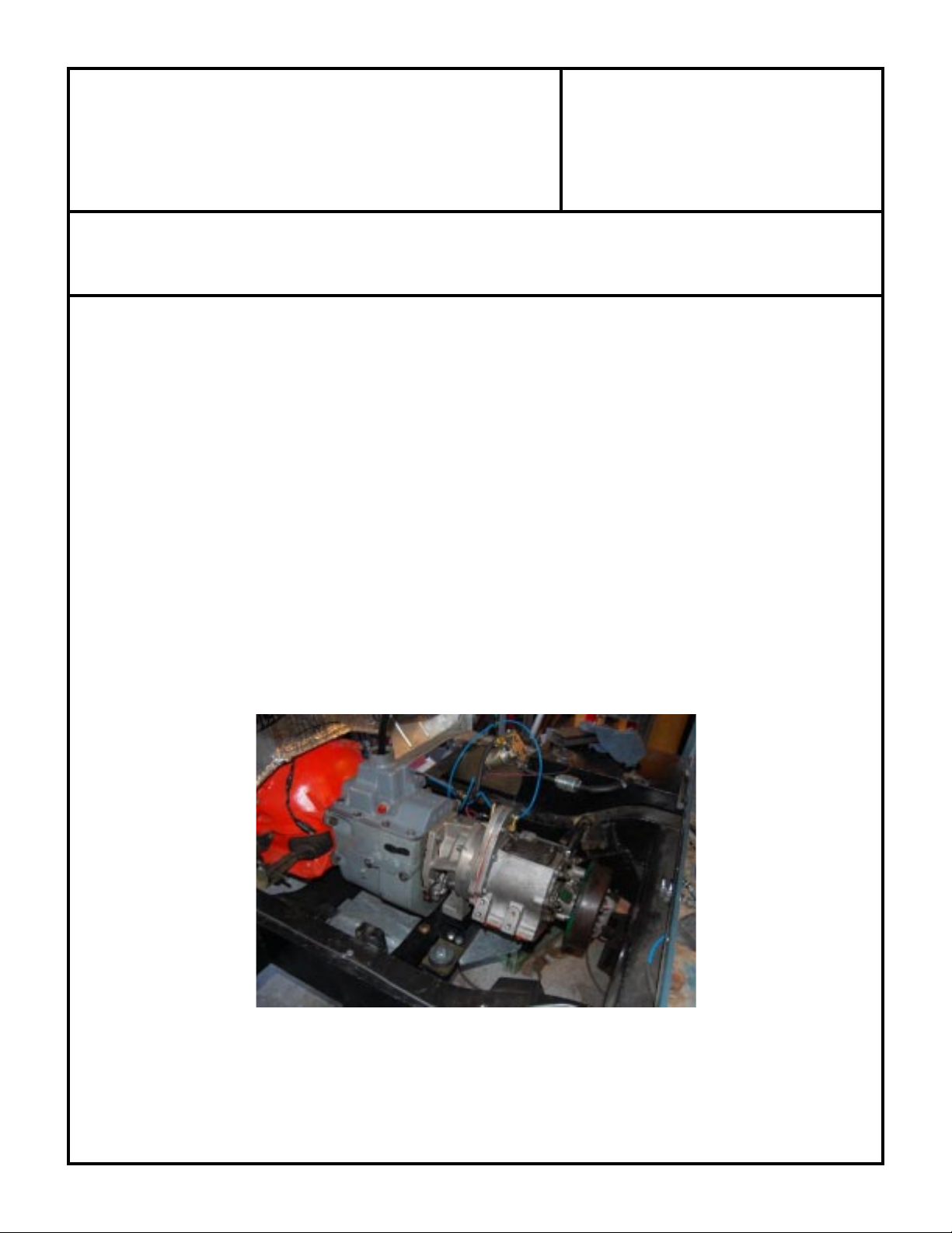
Introduction:
This adapter kit fits Land Rover series I ,II,IIA and III transfer cases and adapts them to a circular 6 pattern. This
adapter allows
durable and strong "series" transfer case. This adapter is to be used in conjunction with either one of our “Dana 300”
style adapters or on some applications it can be bolted directly to a stock transmission tail housing. We have designed
the adapter kit to retain the PTO function on the stock transfer case.
Preparation For Assembly:
Follow the service manual procedure to remove the transfer case from the transmission. Thoroughly inspect the
tranfer case to determine the condition. Overhaul if necessary to insure the quality of your adapter installation.
Procedure:
the series Land Rover owner the opportunity to repower and install different transmissions to the very
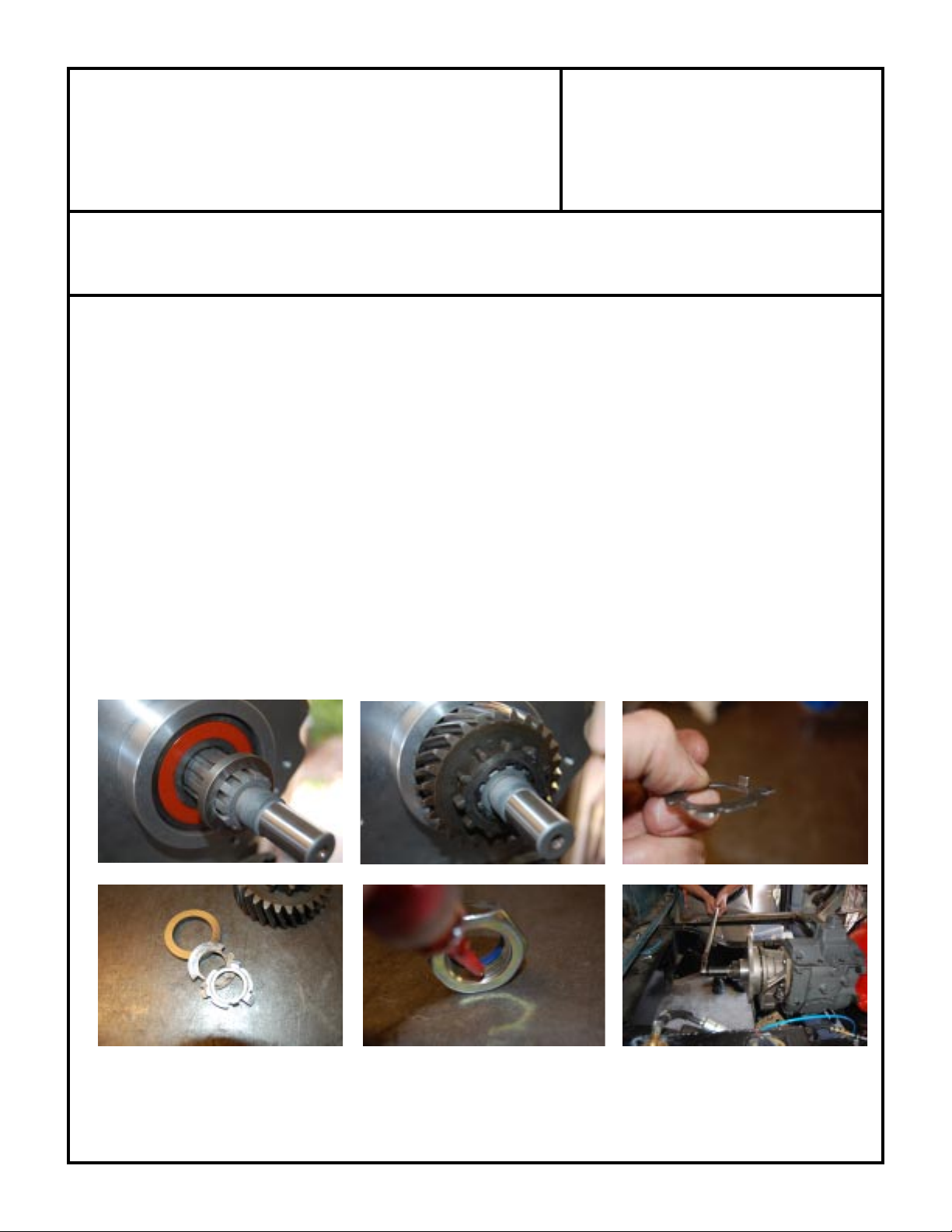
1. Install the drive gear onto the new spud shaft with spacer 716239 behind the drive gear. Then install the original
flat washer and the supplied lock tab. Press the gear fully onto the shaft and test fit the lock washer. The
tangs will need to be trimmed. These parts are retained because they provide lubrication to the splines of the
shaft and input gear. Use locking compound on the new lock nut and torque to 75ft.lbs.
SPECIAL NOTE: The components packaged in this kit have been assembled and machined for specific type of conversions. Modifications to any of the components will
void any possible warranty or return privileges. If you do not fully understand modifications or changes that will be required to complete your conversion, we strongly recommend
that you contact our sales department for more information. This instruction sheet is only to be used for the assembly of Advance Adapter components. We recommend that a
service manual pertaining to your vehicle be obtained for specific torque values, wiring diagrams and other related equipment. These manuals are normally available at automotive
dealerships and parts stores.
Page 3

ADVANCE ADAPTERS INC. P/N: 50-9000
P.O. Box 247, 4320 Aerotech Center Way New Item: (9/09)
Paso Robles, CA 93447 PAGE
Telephone: (800) 350-2223 Fax: (805) 238-4201 Page Rev . Date:
3 OF 6
03-25-10
LAND ROVER SERIES T-CASE to NP
CIRCULAR 6 ADAPTER with JEEP 23 SPLINE
2. Apply a 1/8" bead of high quality silicone on the transfer case
mounting surface, Insure that you encircle the idler pin bore and the
perimeter of the casting.
3. Install the dowel pins into the adapter casting (these are a slip fit, so
be careful not to lose them)
4. Install the assembled adapter plate to the transfer case.
Use locking compound on all of the interior bolts and lock
washers to insure they do not back out in use. Torque 3/8"
bolts to 35 ft.lbs.
5. Install the remaining 3/8" bolts and lock washers. Torque
to 35ft.lbs.
6. Install the new breather elbow into the adapter with sealant on thread.
SPECIAL NOTE: The components packaged in this kit have been assembled and machined for specific type of conversions. Modifications to any of the components will
void any possible warranty or return privileges. If you do not fully understand modifications or changes that will be required to complete your conversion, we strongly recommend
that you contact our sales department for more information. This instruction sheet is only to be used for the assembly of Advance Adapter components. We recommend that a
service manual pertaining to your vehicle be obtained for specific torque values, wiring diagrams and other related equipment. These manuals are normally available at automotive
dealerships and parts stores.
Also install the two 5/16" bolts assemblies to the top of the adapter.
Page 4

ADVANCE ADAPTERS INC. P/N: 50-9000
P.O. Box 247, 4320 Aerotech Center Way New Item: (9/09)
Paso Robles, CA 93447 PAGE
Telephone: (800) 350-2223 Fax: (805) 238-4201 Page Rev . Date:
4 OF 6
03-25-10
LAND ROVER SERIES T-CASE to NP
CIRCULAR 6 ADAPTER with JEEP 23 SPLINE
7. Install idler gear and pan to transfer case as per manual.
8. Test fit PTO cover. Rotate gear assembly to insure there is no
interference with the new nut and PTO cover.The new nut is a
close fit into the bore of the PTO cover pocket bearing. Additional gaskets may need to be stacked due to variances in
transfer case casting thicknesses.
9. Finish assembling the transfer case as per factory instruction
manual.
10.With the replacement engine and transmission combination
positioned within the chassis rails you now have the opportunity
to “clock” the transfer case. The six studs P/N 302069 and
flange nut P/N 302071 are provided for final assembly in the
desired “clocking” rotation.
Note: All threads into the Land Rover transfer case are standard UNC. Park brake linkage and mount system will
need modifiing.
SPECIAL NOTE: The components packaged in this kit have been assembled and machined for specific type of conversions. Modifications to any of the components will
void any possible warranty or return privileges. If you do not fully understand modifications or changes that will be required to complete your conversion, we strongly recommend
that you contact our sales department for more information. This instruction sheet is only to be used for the assembly of Advance Adapter components. We recommend that a
service manual pertaining to your vehicle be obtained for specific torque values, wiring diagrams and other related equipment. These manuals are normally available at automotive
dealerships and parts stores.
Page 5

ADVANCE ADAPTERS INC. P/N: 50-9000
P.O. Box 247, 4320 Aerotech Center Way New Item: (9/09)
Paso Robles, CA 93447 PAGE
5 OF 6
Telephone: (800) 350-2223 Fax: (805) 238-4201 Page Rev . Date:
03-25-10
LAND ROVER SERIES T-CASE to NP
CIRCULAR 6 ADAPTER with JEEP 23 SPLINE
Necessary Chassis Modifications:
The chassis is a large box section ladder style. It is an excellent piece of
engineering. However, close inspection is required. Being that the
chassis is fully enclosed, it can rust from the inside out. New chassis’s
are available from a number of outfits. The vehicles are modular in their
construction making them relatively easy to modify. The battery tray
structure will have to be removed to allow for the installation of a “V”
type engine. The original motor mounts need to be cut off the frame.
Under the bellhousing, the cross member will require a notch similar to
the military LWB to allow for clearance on the front drive shaft.
On some series I,II,IIA ,it is advisable to remove the web on the second
cross member from the front. The web is on the drivers side (LHD). This
provides clearance for the exhaust to pass over the cross member and
down the inside of the chassis. The third (transmission cross member)
will also need modifying. Depending upon your transmission mounting
method. If mounting from the transfer case using the original studs, you
can retain the cross member. It may need to be moved in the chassis
depending upon engine placement. If using the mounting surface
provided on our adapters a new cross member will need to be fabricated.
The park brake bell crank will also have to be modified to maintain the
correct geometry to operate well. The cross shaft may also need to be
modified due to the height of engine placement. On LWB models, the
cross member behind the transfer case (where the original driveline
passed through) will need to be removed and replaced with a section of
rectangular tubing similar to the removable cross member of a Discovery
or a Range Rover.
Completed modified radiator support
SPECIAL NOTE: The components packaged in this kit have been assembled and machined for specific type of conversions. Modifications to any of the components will
void any possible warranty or return privileges. If you do not fully understand modifications or changes that will be required to complete your conversion, we strongly recommend
that you contact our sales department for more information. This instruction sheet is only to be used for the assembly of Advance Adapter components. We recommend that a
service manual pertaining to your vehicle be obtained for specific torque values, wiring diagrams and other related equipment. These manuals are normally available at automotive
dealerships and parts stores.
Page 6

ADVANCE ADAPTERS INC. P/N: 50-9000
P.O. Box 247, 4320 Aerotech Center Way New Item: (9/09)
Paso Robles, CA 93447 PAGE
Telephone: (800) 350-2223 Fax: (805) 238-4201 Page Rev . Date:
6 OF 6
03-25-10
LAND ROVER SERIES T-CASE to NP
CIRCULAR 6 ADAPTER with JEEP 23 SPLINE
Necessary sheet metal modifications:
To maintain the original external appearance of the vehicle and allow for ample cooling capacity the “breakfast” or headlight
panel will need to be modified. The original radiator will not be adequate to keep the replacement engine cool. To make room
for a larger radiator the original radiator support structure needs to be removed. The original radiator overhangs the first cross
member.
The panel is easily modified. Drill through the spot welds and gently lever the two pieces apart. To maintain structural rigidity,
you can use three pieces of 1/8"X 1" flat bar stock. One across the top, spanning the width of the panel, and the two remaining
pieces will be welded vertically and parallel to the center opening. The latch is no longer used.
You will need to purchase military hood latches. This provides the space for a radiator on
top of the first cross member.
It is advisable to convert to power steering. When converting to power steering, the steering
relay is removed.
To provide room for a “V” type engine and maintain the original look of the vehicle
It is necessary to widen the firewall or “bulkhead” to accept the wider engine. This is easily
done by drilling out the spot welds that hold the center panel to the foot well. Remove the
panels individually and save them for reuse. Drill out the spot-welds of the inner kick panel.
The goal is to match to foot well dimensions to the driver side (LHD). Essentially creating
a large factory appearing opening. Fabricate a new center panel keeping in mind the bell
housing size, depending upon engine, transmission and placement .
Bulkhead spot welds
Images of the foot well panels ( left side and then the right)
SPECIAL NOTE: The components packaged in this kit have been assembled and machined for specific type of conversions. Modifications to any of the components will
void any possible warranty or return privileges. If you do not fully understand modifications or changes that will be required to complete your conversion, we strongly recommend
that you contact our sales department for more information. This instruction sheet is only to be used for the assembly of Advance Adapter components. We recommend that a
service manual pertaining to your vehicle be obtained for specific torque values, wiring diagrams and other related equipment. These manuals are normally available at automotive
dealerships and parts stores.
 Loading...