

Page 1

ADVANCE ADAPTERS, INC. P/N: 50-6309
P.O. Box 247, 4320 Aerotech Center Way New Item: (01/98)
Paso Robles, CA 93447 PAGE: 1 OF 3
Telephone: (800) 350-2223 Fax: (805) 238-4201 Page Rev. Date: 01-17-14
GM 700R-4 4X4 APPLICATION TO DANA 300
KIT CONSISTS OF:
No. Qty. Part No. Description
1. 1 51-6300A CASTING (Ref: 711163)
2. 1 52-6309 DANA 300 INPUT SHAFT
3. 1 716308 BEARING (#6209)
4. 1 716511 "O"-RING
5. 1 716517 GASKET
6. 1 716749 NATIONAL SEAL 471870
7. 4 720038 10mm LOCKWASHER
8. 4 720046 10mm 1.5 THREAD BOLT S.H.C.S.
9. 6 723701 3/8"-16 HEX NUT
10. 6 723704 LOCK WASHER
11. 6 723711 STUD BOLT 3/8"-16 x 2" LG.
12. 1 JP001 JEEP INSTRUCTION MANUAL
INSTALLATION INSTRUCTIONS:
This kit is designed to use a stock 700R 4X4 transmission to a Dana 300 transfer case. If you do not have the 4X4 version
of the 700R, you will have to purchase a new output shaft, GM# 8642228. To assembly this adapter, you will have to modify
your output stickout from the back of the transmission case. The proper cut off length is 2.75". This measurement should
be taken from the rear of the transmission case.
1. Starting at the Dana 300 transfer case, remove the 6 socket head bolts from the aluminum index hub on the front side
the transfer case.
2. Using the two slots on the side of this retainer, you will need to pry the retainer out of the transfer case. This retainer
assembly does pilot into the rear output shaft of this transfer case. If the retainer assembly seams tight to remove, try
spinning the rear output shaft.
3. Once the retainer is removed you will need a pair of snap ring pliers to remove the snap ring that retains the drive gear
to the input shaft. Remove the snap ring and the drive gear from the input shaft. The aluminum retainer should now
have the bearing, input shaft, seal, and a snap ring holding the bearing into the retainer. This snap ring must also be
removed to allow the bearing and input shaft to be pressed out of the index housing.
4. The seal will also be required to be pressed out of the index retainer. The retainer should now be empty.
5. Install the new bearing onto the new input shaft. Install both components into the stock retainer and install the stock
snap ring.
6. Install the input drive gear onto the input shaft and retain it with the stock snap ring. Make sure the gear is installed
so that the cogged side of the gear is facing away from the bearing.
SPECIAL NOTE: The components packaged in this kit have been assembled and machined for specific types of conversions. Modifications to any of the
components will void any possible warranty or return privileges. If you do not fully understand the modifications or changes that will be required to complete
your conversion, we strongly recommend that you contact our sales department for more information. This Instruction Sheet is only to be used for the assembly
of Advance Adapter components. We recommend that a service manual pertaining to your vehicle be obtained for specific torque vales, wiring diagrams and
other related equipment. These manuals are normally available at automotive dealerships and parts stores.
Page 2
ADVANCE ADAPTERS, INC. P/N: 50-6309
P.O. Box 247, 4320 Aerotech Center Way New Item: (01/98)
Paso Robles, CA 93447 PAGE: 2 OF 3
Telephone: (800) 350-2223 Fax: (805) 238-4201 Page Rev. Date: 03-10-09
GM 700R-4 4X4 APPLICATION TO DANA 300
7. Install the new seal provided in the kit - the open side towards the transfer case.
8. Apply Loctite 515 or equivalent sealant to the retainer surface and install into
the Dana 300 transfer case. Make sure the pocket bearing is installed in the
Dana 300 output shaft
9. Bolt retainer to the transfer case using the stock bolts. Torque to 10 ft./lbs.
10. This kit fits the 700R 4WD transmission only. The stock 4WD output shaft must
be shortened to a stickout of 2.750" from the rear of the transmission.
11. Install the adapter to the 700R using the metric bolts and lock washers. Make
sure you install the square o-ring between the adapter and the transmission.
12. The transfer case should be test-fitted to the adapter to check for shaft
engagement. Make sure the transfer case fits flush up to the adapter surface.
If not, check for burrs on the shafts and/or output shaft cut off length. Never pull the transfer case to the adapter
using the bolts to draw these components together. The adapter also provides an option of two rotation angles for
the transfer case (stock rotation is 35 degrees).
13. Install a silicone sealant on both sides of the gasket and install the transfer case to the adapter. Note: The gasket will
only fit onto the transfer case in one rotation.
14. Install the nuts onto the new stud bolts and Loctite to secure.
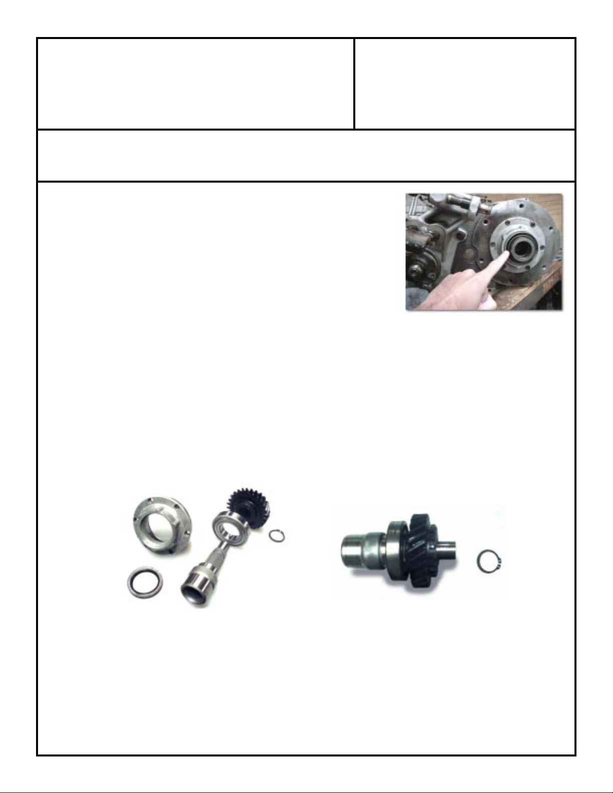
(illustrated in photo right)
.
If for any reason the two bolt surfaces do not slide together, DO NOT FORCE OR PULL TOGETHER with the bolts.
If you have any questions, please call 1-800-350-2223, for technical assistance.
New input shaft & stock parts assembled.AA shaft & bearing with stock parts
SPECIAL NOTE: The components packaged in this kit have been assembled and machined for specific types of conversions. Modifications to any of the
components will void any possible warranty or return privileges. If you do not fully understand the modifications or changes that will be required to complete
your conversion, we strongly recommend that you contact our sales department for more information. This Instruction Sheet is only to be used for the assembly
of Advance Adapter components. We recommend that a service manual pertaining to your vehicle be obtained for specific torque vales, wiring diagrams and
other related equipment. These manuals are normally available at automotive dealerships and parts stores.
Page 3

ADVANCE ADAPTERS, INC. P/N: 50-6309
P. O. Box 247, 4320 Aerotech Center Wa y New Item: (01/98)
Paso Robles, CA 93447 PAGE: 3 OF 3
Telephone: (800) 350-2223 Fax: (805) 238-4201 Page Rev. Date: 01-15-08
GM 700R-4 4X4 APPLICATION TO DANA 300
8642228
51-6300A
SPECIAL NOTE: The components packaged in this kit have been assembled and machined for specific types of conversions. Modifications to any of the
components will void any possible warranty or return privileges. If you do not fully understand the modifications or changes that will be required to complete
your conversion, we strongly recommend that you contact our sales department for more information. This Instruction Sheet is only to be used for the assembly
of Advance Adapter components. We recommend that a service manual pertaining to your vehicle be obtained for specific torque vales, wiring diagrams and
other related equipment. These manuals are normally available at automotive dealerships and parts stores.
 Loading...