

Page 1
ADV ANCE ADAPTERS INC. P/N: 50-5041
P.O. Box 247, 4320 Aerotech Center Way New Item: (6/05)
Paso Robles, CA 93447 PAGE 1 OF 5
Telephone: (800) 350-2223 Fax: (805) 238-4201 Page Rev. Date: 06-05-13
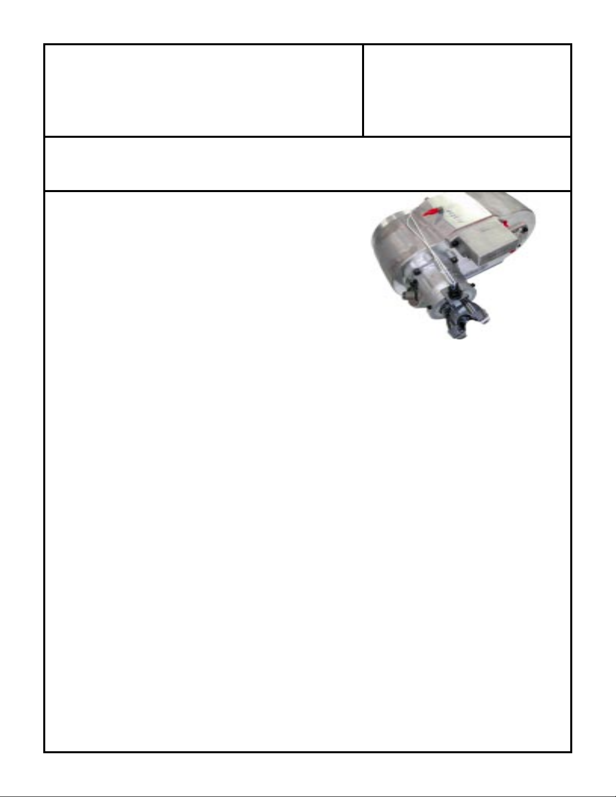
1310 CV VSS
T AILHOUSING RELUCT OR KIT
KIT CONSISTS OF:
No. Qty Part No. Description
1. 1 300619 RELUCTOR SENSOR
2. 3 300386 SET SCREWS
3. 1 300476 YOKE NUT
4. 1 300502 SEAL
5. 1 716380 VSS TAILHOUSING RING
6. 1 716381 VSS MOUNTING BLOCK
7. 1 716383 PIGTAIL FOR VSS SENSOR
8. 2 721401 8-32 x 1.5" S.H.C.S.
9. 1 721402 8-32 x .625 S.H.C.S.
THE FOLLOWING ASSEMBLED BY AA:
10. 1 716382 MODIFIED RELUCTOR RING
11. 1 716386 MODIFIED YOKE
WARNING:
Please read all instructions carefully. If the instructions are not followed, damage to powertrain parts and supplied kit
parts will occur. Please also note: This kit is intended to fit only Advance Adapters 32 spline output shaft upgrade kits.
Please do not try to fit onto any components other than specified. This kit should only be used with non-computer
controlled transmissions. When retrofitting a 4L60E/4L80E, the VSS should be located between the transmission and
the transfer case, otherwise shifting problems will exist when in low range. Feel free to contact Advance Adapters at
any point or if you have difficulties (1-800-350-2223).
NP231 WARNING: The seal provided in the kit
will not work in an S.Y.E. kit. If using an S.Y.E. kit,
please retain the existing seal (if originally a CV),
contact Advance Adapters for P/N 716751, or use
P/N CR 18662 for a local replacement.
GENERAL INFORMATION:
This kit is intended to retrofit a stock GM VSS sensor onto a powertrain when a '93 through current GM engine is used.
When a computer controlled engine is swapped into a vehicle, there are a variety of transmissions which can be used.
Regardless of which transmission is used, this kit will retrofit the sensor to the transfer case tailhousing. When fitted
with an Advance Adapters output shaft, the specific transfer cases include the Dana 20, Dana 300, New Process 231,
and the Atlas transfer case. Since this kit is a true retrofit, the stock speedometers found in these tailhousings will remain
functional; this allows both the stock gauge and the late model VSS be functional on the same vehicle. This also allows
the tire size and gear ratio to be compensated so that the gauge reads correctly and the computer for the engine also
reads correctly.
With the VSS operational, the engine can determine how fast the vehicle is traveling. The late model engines can take
the VSS signal and use it to adjust for freeway driving, apply corrected fuel economy, and calculate the best performance
SPECIAL NOTE: The components packaged in this kit have been assembled and machined for specific type of conversions. Modifications to
any of the components will void any possible warranty or return privileges. If you do not fully understand modifications or changes that will be
required to complete your conversion, we strongly recommend that you contact our sales department for more information. This instruction sheet
is only to be used for the assembly of Advance Adapter components. We recommend that a service manual pertaining to your vehicle be obtained
for specific torque values, wiring diagrams and other related equipment. These manuals are normally available at automotive dealerships and parts
stores.
Page 2
ADV ANCE ADAPTERS INC. P/N: 50-5041
P.O. Box 247, 4320 Aerotech Center Way New Item: (6/05)
Paso Robles, CA 93447 PAGE 2 OF 5
Telephone: (800) 350-2223 Fax: (805) 238-4201 Page Rev . Date: 03-24-09
1310 CV VSS
T AILHOUSING RELUCT OR KIT
for any given moment. Overall, having an operational VSS on a late model engine will yield the best performance possible.
Some products may try to "trick" or mask this signal; the Advance Adapters TruPulse kit uses factory GM sensors to
give a genuine signal to the computer. Please make sure that your harness and computer are programmed to accept
this signal.
GETTING STARTED:
Please take an inventory and become familiar with the parts included in the kit. Do not substitute any parts. If there
is a shortage or if you have any questions please call us at 1-800-350-2223. Also, make sure all parts are clean and
free of any loose debris. Be sure that you have an Advance Adapters upgrade kit installed on the transfer case. Only
basic hand tools are required other than a torque wrench and possibly a yoke puller (a dead-blow hammer can be
substituted when attempting to remove the transfer case yoke).
DISASSEMBLY:
NOTE: You may find it easier to install this kit by removing the transfer case from the vehicle. If so, consult the owner's
manual for instructions.
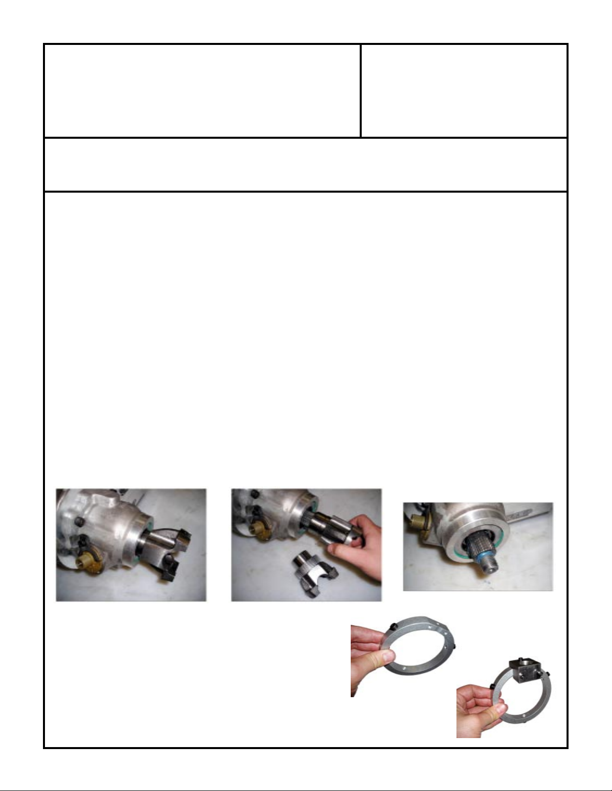
1. Start by removing the rear driveshaft and yoke from the transfer case and set aside.
2. Please remove the seal from the housing and discard.
3. Clean the output shaft and related parts and make sure there is no debris. Also take the chance to clean the outside
machined surface on the tailhousing to prepare it for the tailhousing ring.
ASSEMBLY:
1. Please find the new seal provided in the kit. Tap the seal into the
tailhousing. Use even pressure to prevent distortion of the seal
face. The seal should be pressed to the bottom of the seal bore
in the tailhousing which is approximately 1/8" below flush with the
tailhousing. Please take a small dab of grease and/or oil to
lubricate the lip portion of the seal.
2. Locate the sensor mounting block and ring. Install the three set screws into the ring and
mount the sensor block to the ring. At this time tighten the block bolts in finger-tight only.
Page 3

ADV ANCE ADAPTERS INC. P/N: 50-5041
P.O. Box 247, 4320 Aerotech Center Way New Item: (6/05)
Paso Robles, CA 93447 PAGE 3 OF 5
Telephone: (800) 350-2223 Fax: (805) 238-4201 Page Rev . Date: 06-05-13
1310 CV VSS
T AILHOUSING RELUCT OR KIT
3. Locate the sensor, and start it into the block. Place the ring over the tailhousing. You will notice that the ring can
be rotated to any position. Make note of the location of the floorboard, skid plate, exhaust, etc. Choose a position
that will be clear of any objects/heat. Position it so it sits evenly on the tailhousing. Screw in each set screw lightly,
one at a time. Please start with very light pressure until all have been started. Go over all the set screws 2-3 times
until they are all tightened evenly. Double check to make sure that the ring is still sitting properly.
4. Find your new yoke. You will notice that the reluctor ring has been pressed onto the yoke by Advance Adapters.
Do no attempt to move, relocate, or disturb the reluctor ring; it has been positioned specifically for your kit. Place
the yoke "driveshaft side down" on a bench. Apply a small bead of silicon to the internal splines. Make sure the
bead makes it all the way around the inside perimeter. Start the yoke onto the output shaft. Do not push it all the
way on. You should push the yoke on just far enough so that the threads are accessible for the nut. Take the nut
and start it by hand. You will notice that it gets difficult after the first couple of turns. Use a 1-1/8" socket and fully
tighten the nut. If you are doing the VSS installation with the transfer case still in the vehicle, torque the nut to 150
ft./lbs. If you are doing the installation in a bench, do your best to get it tight; do the final torque on the nut when
the transfer case is in the vehicle.
SPECIAL NOTE: The components packaged in this kit have been assembled and machined for specific type of conversions. Modifications to
any of the components will void any possible warranty or return privileges. If you do not fully understand modifications or changes that will be
required to complete your conversion, we strongly recommend that you contact our sales department for more information. This instruction sheet
is only to be used for the assembly of Advance Adapter components. We recommend that a service manual pertaining to your vehicle be obtained
for specific torque values, wiring diagrams and other related equipment. These manuals are normally available at automotive dealerships and parts
stores.
Page 4

ADV ANCE ADAPTERS INC. P/N: 50-5041
P.O. Box 247, 4320 Aerotech Center Way New Item: (6/05)
Paso Robles, CA 93447 PAGE 4 OF 5
Telephone: (800) 350-2223 Fax: (805) 238-4201 Page Rev . Date: 06-21-05
1310 CV VSS
T AILHOUSING RELUCT OR KIT
5. Tighten the top and non-slotted socket head cap screws. Please verify that the bolt (that has a slot through it) needs
to be loose. Thread the sensor down until it gets close to the reluctor ring. Use a feeler gauge to set a gap of 0.012"
+/-0.002". Make certain that the probe of the sensor is lining up with the top of one of the teeth on the reluctor ring.
Spin the shaft and recheck this gap at two more locations on the reluctor. Once the gap has been set, snug the
loose retaining bolt. Verify that the sensor has not moved by using the feeler gauge. Also make sure that the bolt
is snug enough that the sensor is not able to spin in the mounting block.
SPECIAL NOTE: The components packaged in this kit have been assembled and machined for specific type of conversions. Modifications to
any of the components will void any possible warranty or return privileges. If you do not fully understand modifications or changes that will be
required to complete your conversion, we strongly recommend that you contact our sales department for more information. This instruction sheet
is only to be used for the assembly of Advance Adapter components. We recommend that a service manual pertaining to your vehicle be obtained
for specific torque values, wiring diagrams and other related equipment. These manuals are normally available at automotive dealerships and parts
stores.
Page 5

ADV ANCE ADAPTERS INC. P/N: 50-5041
P.O. Box 247, 4320 Aerotech Center Way New Item: (6/05)
Paso Robles, CA 93447 PAGE 5 OF 5
Telephone: (800) 350-2223 Fax: (805) 238-4201 Page Rev . Date: 06-21-05
1310 CV VSS
T AILHOUSING RELUCT OR KIT
6. If wiring harness has correct plug installed, plug in the sensor now. If not, use the included pigtail to wire the sensor
into the wiring harness. The schematic below shows the correct description and color code for 1999 & newer sensor
provided in this kit. Please refer to the wiring diagram specific to your engine application for the correct circuit # and
computer pins to which the pigtail should be terminated. Also note that GM used twisted pair wire for this sensor
to eliminate any signal electrical interference.
7. Double check all set screws and bolts. Also check all the alignments of parts. Reinstall transfer case (if it has been
removed) and all other parts necessary to drive the vehicle. Use a scan tool to access the operational data and make
sure the correct signal is being read by the ECM.
SPECIAL NOTE: The components packaged in this kit have been assembled and machined for specific type of conversions. Modifications to
any of the components will void any possible warranty or return privileges. If you do not fully understand modifications or changes that will be
required to complete your conversion, we strongly recommend that you contact our sales department for more information. This instruction sheet
is only to be used for the assembly of Advance Adapter components. We recommend that a service manual pertaining to your vehicle be obtained
for specific torque values, wiring diagrams and other related equipment. These manuals are normally available at automotive dealerships and parts
stores.
 Loading...