

Page 1
ADVANCE ADAPTERS INC. P/N: 50-1700
P.O. Box 247, 4320 Aerotech Center Way Old Part No: 711017
Paso Robles, CA 93447 PAGE 1 OF 3
Telephone: (800) 350-2223 Fax: (805) 238-4201 Page Rev. Date: 08-08-14
TURBO 400 TO T OYOTA
LAND CRUISER 1980-89 FJ60 (4-SPEED)
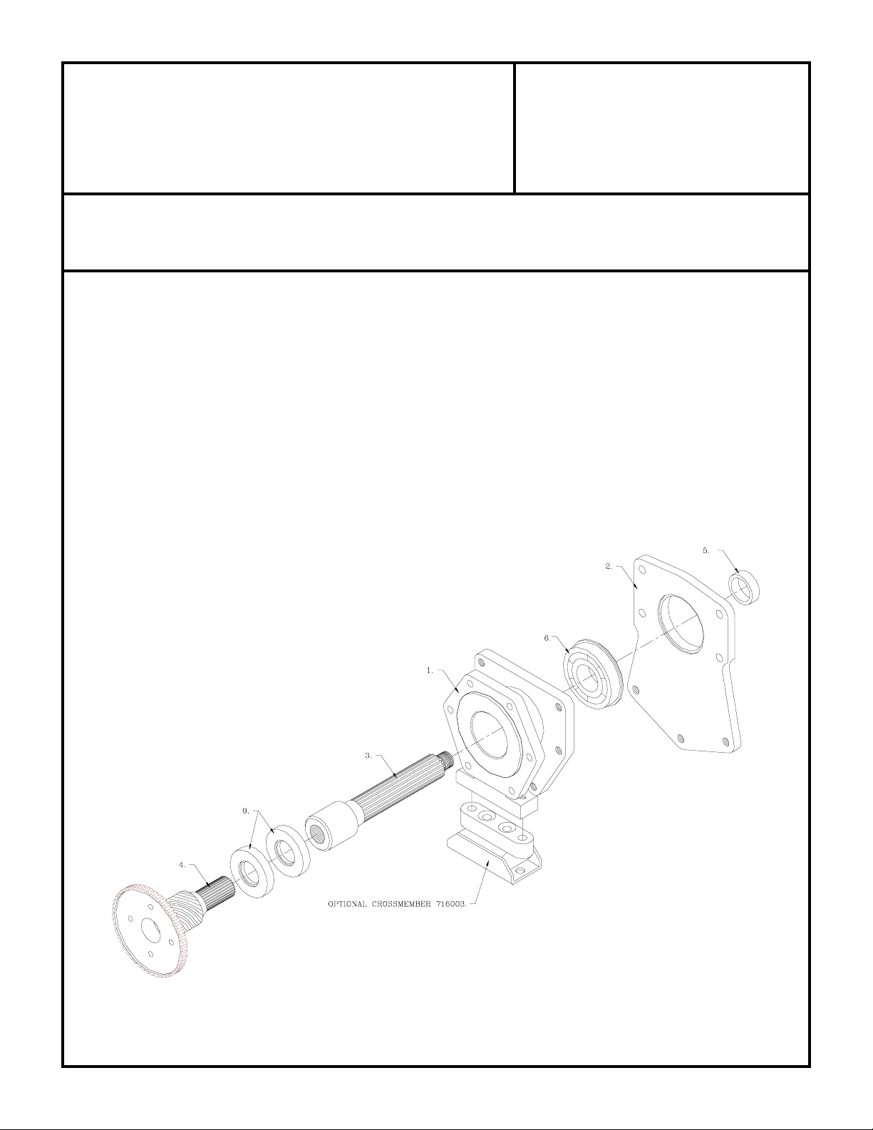
KIT CONSISTS OF:
No. Qty Part No. Description
1. 1 51-0700 ADAPTER CASTING (Ref: 711107)
2. 1 51-0800 ADAPTER PLATE (Ref: 711108)
3. 1 52-8300 SPUD SHAFT
4. 1 52-3200 MAIN SHAFT (Ref: 711332)
5. 1 716150 BUSHING/GEAR LOCATOR
6. 1 716301 SEALED BEARING.
7. 1 716507 GASKET
8. 1 716510 GASKET
9. 2 716700 SEAL (NAT. #331107N)
10. 6 723701 HEX NUTS
11. 6 723711 3/8"-16 x 2" STUDS
12. 8 724302 7/16" FLATWASHERS
13. 2 724309 7/16" H.H.C.S.
14. 1 724311 H.H.C.S. 7/16"-14 x 3-1/2" GR 5
15. 2 724312 7/16"-14 x 4" H.H.C.S.
16. 2 724328 7/16"-14 x 1-1/4" H.H.C.S.
17. 1 728703 STOCK SHAFT NUT
18. 1 TLC001 LAND CRUISER INSTR. MANUAL
If your transfer case was coupled to a
manual transmission, Toyota used a single
lip seal in the front of the transfer case. We
recommend changing the seal with a
double lip seal that was used on the stock
automatic applications.
Toyota # 90316-48003
Vehicles that were equipped originally with a
manual transmission used a sleeve that locates
the gear for the transmission rear bearing and
provides a seal surface. These applications do
not require the use of our spacer P/N 716142.
You must retain this stock gear spacer on these
applications. All other vehicles have the seal
surface on the gear and will need to use the
gear spacer included in this kit.
SPECIAL NOTE: The components packaged in this kit have been assembled and machined for specific type of conversions. Modifications to any of the
components will void any possible warranty or return privileges. If you do not fully understand modifications or changes that will be required to complete
your conversion, we strongly recommend that you contact our sales department for more information. This instruction sheet is only to be used for the assembly
of Advance Adapter components. We recommend that a service manual pertaining to your vehicle be obtained for specific torque values, wiring diagrams
and other related equipment. These manuals are normally available at automotive dealerships and parts stores.
Page 2

ADVANCE ADAPTERS INC. P/N: 50-1700
P.O. Box 247, 4320 Aerotech Center Way Old Part No: 711017
Paso Robles, CA 93447 PAGE 2 OF 3
Telephone: (800) 350-2223 Fax: (805) 238-4201 Page Rev. Date: 08-03-11
TURBO 400 TO T OYOTA
LAND CRUISER 1980-89 FJ60 (4-SPEED)
GM TH400 3 SPEED AUTOMATIC
The GM TH400 has a case length of 24-3/4", 13 bolts for holding the oil pan in position, and is available in 3 different engine
to transmission bolt patterns. Make sure you have selected the proper TH400 for your particular engine. The rear side
of the transmission case will have a hex shaped bolt pattern that uses 6 bolts. There are several various lengths of output
shafts that these transmissions have been equipped with, and all of our TH400 output shafts will be interchangeable with
your transmission. The new shaft supplied with your kit should be installed by a competent mechanic. The speedometer
gear is normally located in the tailhousing, but when adapting it to the transfer case, the location will change to the backside
of the transfer case. The rear transmission support will now be located on the new adapter housing.
When installing the new transfer case adapter, make sure that the coupler and the output shaft do not bottom out. We have
found on occasion that a transmission output shaft may be slightly longer than what we have allowed for. When coupling
the adapter housing and spud shaft to the back of the transmission, there should not be any interference. DO NOT FORCE
THE NEW TAILHOUSING ONTO THE TRANSMISSION. If assistance is needed, please feel free to call the number
listed above.
When assembling the adapter housing to the transmission case, we have provided you with a new gasket to prevent fluid
leakage. This gasket is a stock GM item that is used on all TH400 installations.
All installations will require the use of a transmission cooler. The cooler can be either installed in the radiator or a remote
location is acceptable. The transmission shift control can either be a Hurst floor mounted type shifter, or sometimes the
existing column shift can be modified on certain applications.
The stock transfer case shift linkage must have a new mounting bracket fabricated. We do not offer any brackets for this
stock linkage.
The 19 spline transfer case is a 2 piece case design. You will need to split it in half to remove it from the vehicle and to
install it to the new adapter. The transfer case is rather complicated, so you should have a shop manual on hand be starting.
INSTALLATION:
The output shaft we have provided will need to be installed into the TH400. Install the 6 studs into the TH400 using Loctite
to secure them. Press the seals into the casting with the open sides opposite each other (see Page 3). Press the bearing
onto the spud shaft with the snap ring end of the bearing towards the transfer case. Press the bearing and spud shaft into
the casting. (Note: When pressing in the bearing, press on the outer race). The flat adapter plate and gasket can now
be positioned up to the adapter housing. The gear spacer bushing must then be installed on the spud shaft. Next, the front
half of the transfer case will need to be secured with the short 7/16" bolts. Reinstall the output gear and P.T.O. spacer
on the spud shaft. The remainder of the reassembly should be done as per your shop manual. The long 7/16" bolts will
replace the stock metric bolt that fasten to the adapter. Once completely tighten re-install the stock flange nut on the end
of our shaft, torque to 75ft/lbs.
On most installations, a slight pan modification will be required for clearance of the front universal yoke. This modification
will be necessary on both the metal pan and the aluminum transmission case. The area where the pan and case come
together (that has the bolt holding the two) will need to be ground down almost even with the body of the bolt. The bolt
SPECIAL NOTE: The components packaged in this kit have been assembled and machined for specific type of conversions. Modifications to any of the
components will void any possible warranty or return privileges. If you do not fully understand modifications or changes that will be required to complete
your conversion, we strongly recommend that you contact our sales department for more information. This instruction sheet is only to be used for the assembly
of Advance Adapter components. We recommend that a service manual pertaining to your vehicle be obtained for specific torque values, wiring diagrams
and other related equipment. These manuals are normally available at automotive dealerships and parts stores.
Page 3

ADVANCE ADAPTERS INC. P/N: 50-1700
P.O. Box 247, 4320 Aerotech Center Way Old Part No: 711017
Paso Robles, CA 93447 PAGE 3 OF 3
Telephone: (800) 350-2223 Fax: (805) 238-4201 Page Rev. Date: 08-08-14
TURBO 400 TO T OYOTA
LAND CRUISER 1980-89 FJ60 (4-SPEED)
may need to be replaced with a socket head cap screw.
These modifications can be done with the pan still
attached to the transmission case. The metal pan will
need the corner recessed approximately 1/2". These
modifications should be made prior to assembly into
the vehicle. In order to allow for additional front
driveline clearance, we recommend that the engine
and transfer case be offset to the driver's side on
vehicles having front driveshafts located on the
passenger's side. On Jeep and Toyota Land Cruiser
conversions, this can be approximately 1" offset of
centerline.
SPECIAL NOTE: The components packaged in this kit have been assembled and machined for specific type of conversions. Modifications to any of the
components will void any possible warranty or return privileges. If you do not fully understand modifications or changes that will be required to complete
your conversion, we strongly recommend that you contact our sales department for more information. This instruction sheet is only to be used for the assembly
of Advance Adapter components. We recommend that a service manual pertaining to your vehicle be obtained for specific torque values, wiring diagrams
and other related equipment. These manuals are normally available at automotive dealerships and parts stores.
 Loading...