

Page 1
ADV ANCE ADAPTERS INC. P/N: 50-1600
P.O. Box 247, 4320 Aerotech Center Way Old Part No: 711016
Paso Robles, CA 93447 PAGE 1 OF 3
Telephone: (800) 350-2223 Fax: (805) 238-4201 Page Rev . Date: 12-27-01
TURBO 400 TO T OYOTA
LANDCRUISER 1974-1982 (4-SPEED)
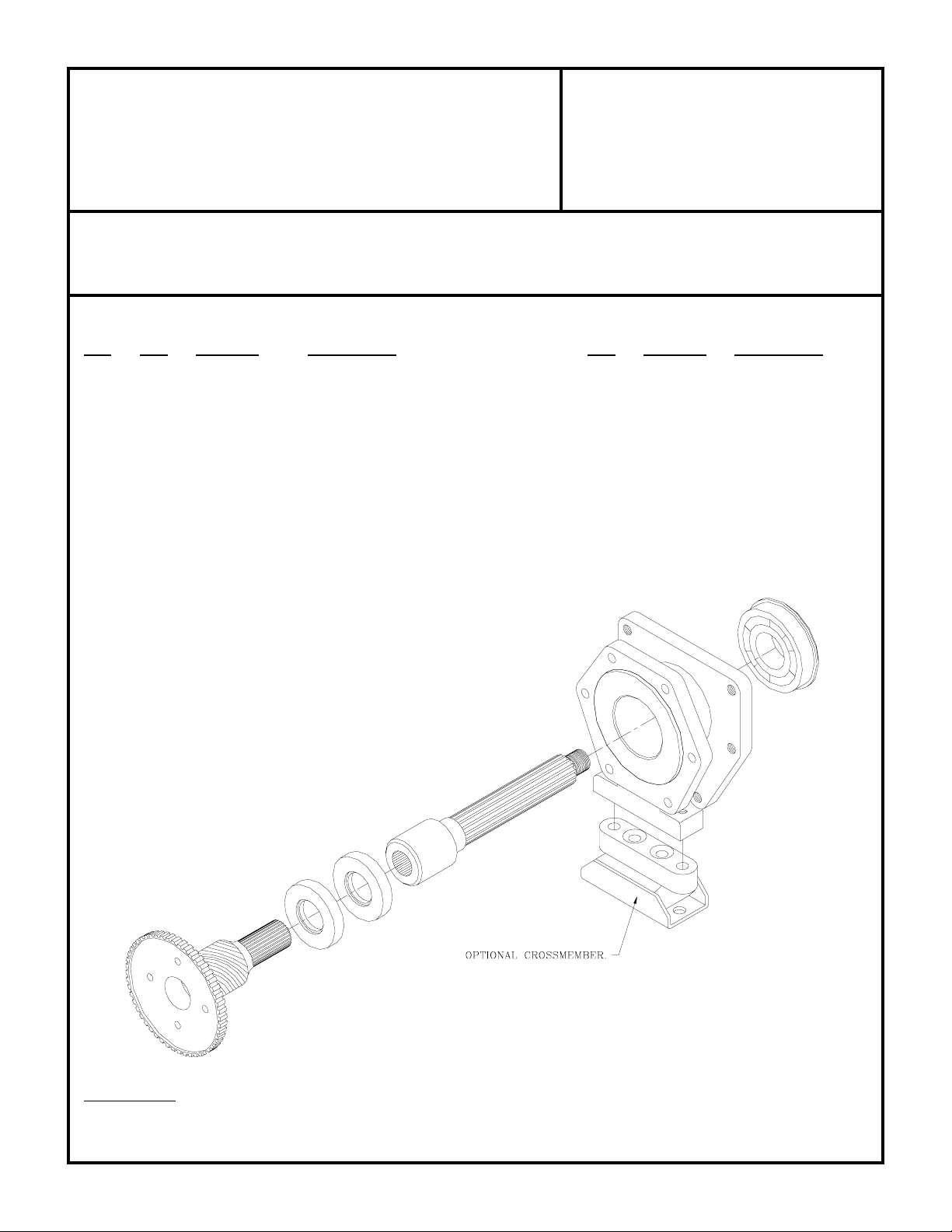
KIT CONSISTS OF:
No. Qty Part No. Description
1. 1 51-0700 ADAPTER CASTING (Ref: 711107)
2. 1 52-1600 SPUD SHAFT (Ref: 711316)
3. 1 52-3200 MAIN SHAFT (Ref: 711332)
4. 1 715520 BRACKET
5. 1 716301 SEALED BEARING
6. 1 716507 GASKET
7. 1 716510 GASKET
8. 2 716700 SEAL (NAT. #331107N)
9. 4 723116 5/16"LOCKWASHERS
10. 4 723118 BOLTS
11. 6 723701 HEX NUTS
12. 6 723711 3/8"-16 x 2" STUDS
13. 5 724302 7/16" FLATWASHERS
14. 3 724345 7/16"-14 x 5" H.H.B.
15. 2 724349 7/16"-14 x 1-1/2" H.H.B.
16. 1 728701 NYLON NUT
17. 1 728702 7/8" FLATWASHER
18. 1 TLC001 LAND CRUISER INSTR. MANUAL
OPTIONAL ITEMS:
Qty Part No. Description
1 716004 CROSSMEMBER MT.
SPECIAL NOTE: The components packaged in this kit have been assembled and machined for specific type of conversions. Modifications to any of the
components will void any possible warranty or return privileges. If you do not fully understand modifications or changes that will be required to complete
your conversion, we strongly recommend that you contact our sales department for more information. This instruction sheet is only to be used for the assembly
of Advance Adapter components. We recommend that a service manual pertaining to your vehicle be obtained for specific torque values, wiring diagrams
and other related equipment. These manuals are normally available at automotive dealerships and parts stores.
Page 2

ADV ANCE ADAPTERS INC. P/N: 50-1600
P.O. Box 247, 4320 Aerotech Center Way Old Part No: 711016
Paso Robles, CA 93447 PAGE 2 OF 3
Telephone: (800) 350-2223 Fax: (805) 238-4201 Page Rev . Date: 12-1 1-00
TURBO 400 TO T OYOTA
LAND CRUISER 1974-1982 (4-SPEED)
GM TURBO 400 3 SPEED AUTOMATIC:
The GM TH400 has a case length of 24-3/4", 13 bolts for holding the oil pan in position and is available in 3 different engine
to transmission bolt patterns. Make sure you have selected the proper TH400 for your particular engine. The rear side
of the transmission case will have a hex shaped bolt pattern that uses 6 bolts. There are several various lengths of output
shafts that the transmission has been equipped with and all of the new Advance Adapter output shafts will be
interchangeable with your transmission. The new shaft supplied with your kit should be installed by a competent mechanic
The speedometer gear is normally located in the tailhousing, but when adapting it to the transfer case, the location will
change to the backside of the transfer case. The rear transmission support will now be located on the new adapter housing
or, in some cases, on the transfer case.
When installing the new transfer case adapter, make sure that the coupler and the output shaft do not bottom out. We have
found on occasion that a transmission output shaft may be slightly longer than we have allowed for and when coupling
into our new spud shaft, we find a small amount of interference. The adapter housing and spud shaft must be assembled
to the back of the transmission without interference. DO NOT FORCE THE NEW TAILHOUSING ONTO THE
TRANSMISSION. If assistance is needed, please feel free to call the number listed above.
ASSEMBLY:
Install the 6 studs in the TH400 with loctite. Install the seals into the casting as shown in the diagram. They must go in
through the transmission side of the adapter and the open sides should be opposite each other (see drawing on last page).
Press bearing onto the shaft. Using the outer edge of the bearing, press it into the casting. The adapter can now be bolted
to the transmission with the 6 hex nuts. The two 7/16"-14 x 1-1/2" bolts will be installed into the transfer case through
the P.T.O. cover. The remaining three bolts will install from the back of the transfer case and secure the unit. Install the
drive gear and P.T.O. spacer as per your Toyota manual. Reinstall the inspection cover. The linkage pivot must be
positioned so that the threaded boss is pointing toward the front of the transmission. Install over the modulator valve with
the 4 provided bolts and lockwasher. The stock linkage bolts to this bracket.
On most installations, pan modification will be required for clearance of the front Universal yoke. This modification will
be necessary on both the metal pan and the aluminum transmission case. The area where the pan and case come together
that has the bolts holding the two, will need to be ground down almost even with the body of the bolt. The bolt may need
to be replaced with a socket head cap screw. The modifications can be done with the pan still attached to the transmission
case. The metal pan will need the corner recessed approximately 1/2". The modifications should be made prior to assembly
into the vehicle. In order to allow for additional front drive line clearance, we recommend that the engine and transfer case
be offset to the driver's side on vehicles having front drive shafts located on the passenger's side.
Additional front driveshaft clearance may be gained by using a small yoke and U-Joint (AA PART# 716370) for coarse
spline, 1966-1977, or (AA PART # 716371) for fine spline (1977-80) transfer case front output shafts. This modification
needs to be completed by an experienced driveshaft shop to eliminate any misalignment and vibrations.
All installations will require the use of a transmission cooler. The cooler can be either installed in the radiator or a remote
location is acceptable. The transmission shift control can either be a Hurst floor mounted type shifter or sometimes the
existing column shift can be modified on certain applications.
SPECIAL NOTE: The components packaged in this kit have been assembled and machined for specific type of conversions. Modifications to any of the
components will void any possible warranty or return privileges. If you do not fully understand modifications or changes that will be required to complete
your conversion, we strongly recommend that you contact our sales department for more information. This instruction sheet is only to be used for the assembly
of Advance Adapter components. We recommend that a service manual pertaining to your vehicle be obtained for specific torque values, wiring diagrams
and other related equipment. These manuals are normally available at automotive dealerships and parts stores.
Page 3

ADV ANCE ADAPTERS INC. P/N: 50-1600
P.O. Box 247, 4320 Aerotech Center Way Old Part No: 711016
Paso Robles, CA 93447 PAGE 3 OF 3
Telephone: (800) 350-2223 Fax: (805) 238-4201 Page Rev . Date: 12-1 1-00
TURBO 400 TO T OYOTA
LAND CRUISER 1974-1982 (4-SPEED)
We recommend that Loctite be used on all bolts. We have included a new nut and flat washer for use on the end of the
output shaft. This 7/8"-16 special nylon lock nut is available through most Jeep stores. You should never reuse the nylon
lock nut in order to maintain the gears in their secure position.
Refer to the Land Cruiser Instruction manual for additional information concerning the transfer case control linkage
SPECIAL NOTE: The components packaged in this kit have been assembled and machined for specific type of conversions. Modifications to any of the
components will void any possible warranty or return privileges. If you do not fully understand modifications or changes that will be required to complete
your conversion, we strongly recommend that you contact our sales department for more information. This instruction sheet is only to be used for the assembly
of Advance Adapter components. We recommend that a service manual pertaining to your vehicle be obtained for specific torque values, wiring diagrams
and other related equipment. These manuals are normally available at automotive dealerships and parts stores.
 Loading...