

Page 1
ADVANCE ADAPTERS, INC. P/N: 50-0430
P.O. Box 247, 4320 Aerotech Center Way New Kit: (02/03)
Paso Robles, CA 93447 PAGE: 1 OF 4
Telephone: (800) 350-2223 Fax: (805) 238-4201 Page Rev. Date: 05-01-13
GM 4L60E TO NP TRANSFER CASES (23SPL)
KIT CONSISTS OF:
No. Qty Part No. Description
1. 1 51-0405 4L60E / UNIVERSAL ADAPTER
2. 1 51-6800 ADAPTER CASTING (Ref: 711168)
3. 1 52-9101 700R-4 SHAFT (23-Splines)
4. 1 300619 RELUCTOR SENSOR
5. 1 716079 22mm PLUG
6. 1 716072 RELUCTOR RING CLAMP RING
(
One piece reluctor, bolt torque 10 ft-lbs.)
7. 1 716082 700R PLASTIC WASHER
8. 1 716511 O-RING (51-6800 CASTING)
9. 1 716517 GASKET, NP208 T/C
10. 1 716729 SEAL (NAT. #456057) (ADAPTER)
11. 6 720015 10mm FLAT WASHER (USE ON 10mm BOLTS)
12. 6 720037 10mm x 1.5mm x 35mm H.H.C.S. (INTO 4L60 CASE)
13. 6 720038 10mm LOCK WASHER (USE ON 10mm BOLTS)
14. 4 720046 S.H.C.S. 10mm-1.5 X 40mm LG. (51-6800 TO THE 51-0405)
15. 6 723701 NUT 3/8"-16 PLATED (USE ON STUDS)
16. 6 723704 3/8" LOCKWASHERS (USE ON STUDS)
17. 6 723711 STUD BOLT 3/8"-16 x 2" LG (TRANSFER CASE STUDS)
18. 2 723730 S.H.C.S. 3/8"-16 x 1-1/4" LG. (STUD REPLACEMENT)
19. 1 JP001 JEEP INSTRUCTION MANUAL
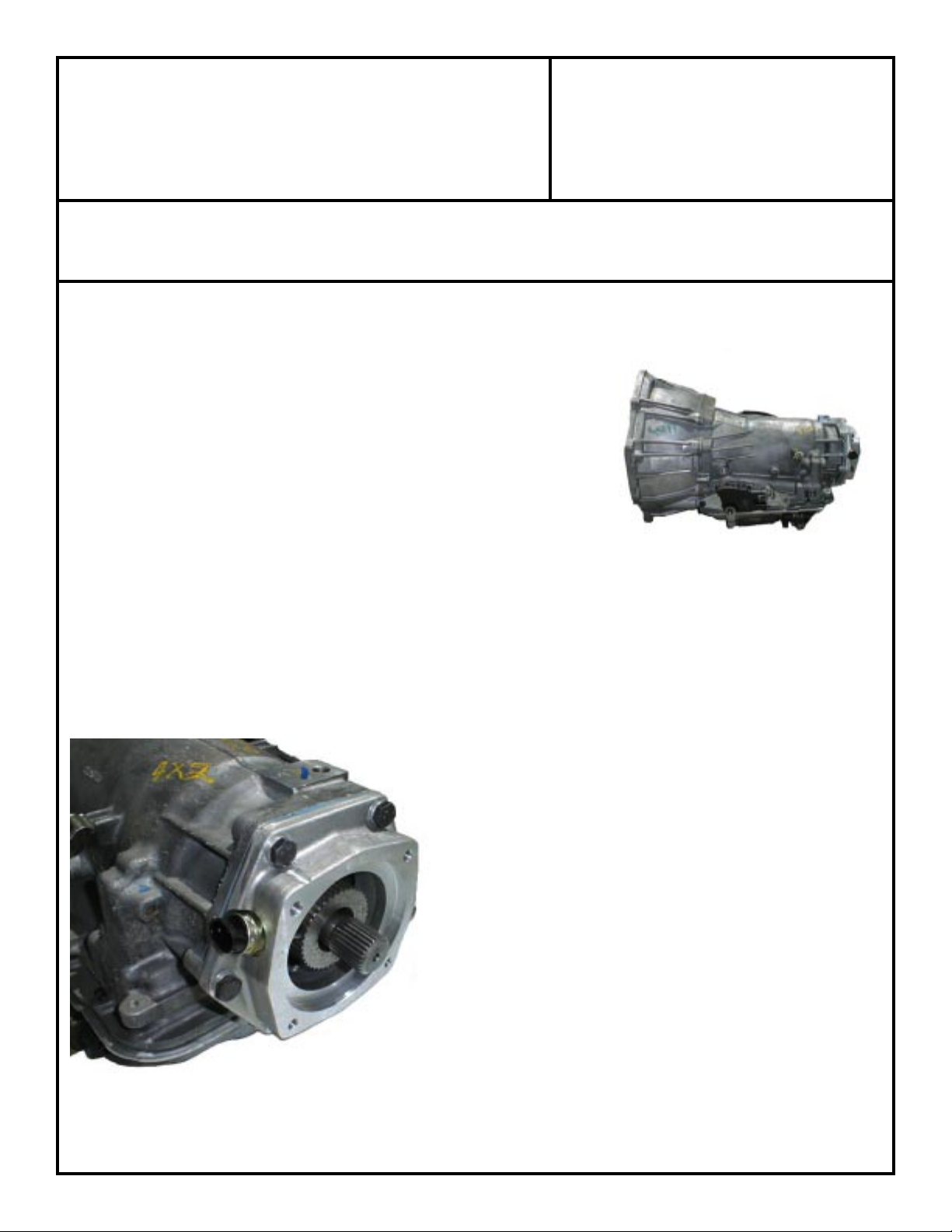
In 1996, GM produced a newer version of its electronically controlled
4L60E. This 4L60E transmission is 21-1/2" long and has a removable
bellhousing. It has a hex bolt pattern on the output side of the
transmission, similar to a TH400.
OPTIONAL ITEMS:
Qty Part No. Description
1 716008 Crossmember mount
The kit which you have purchased was designed not only to
adapt the 4L60E to the NP231 case, but also to maintain the
pulse generator to run the computer. We have included a
700R4 shaft in this kit to be installed in the transmission. Once
installed in the transmission, you may begin to assembly the
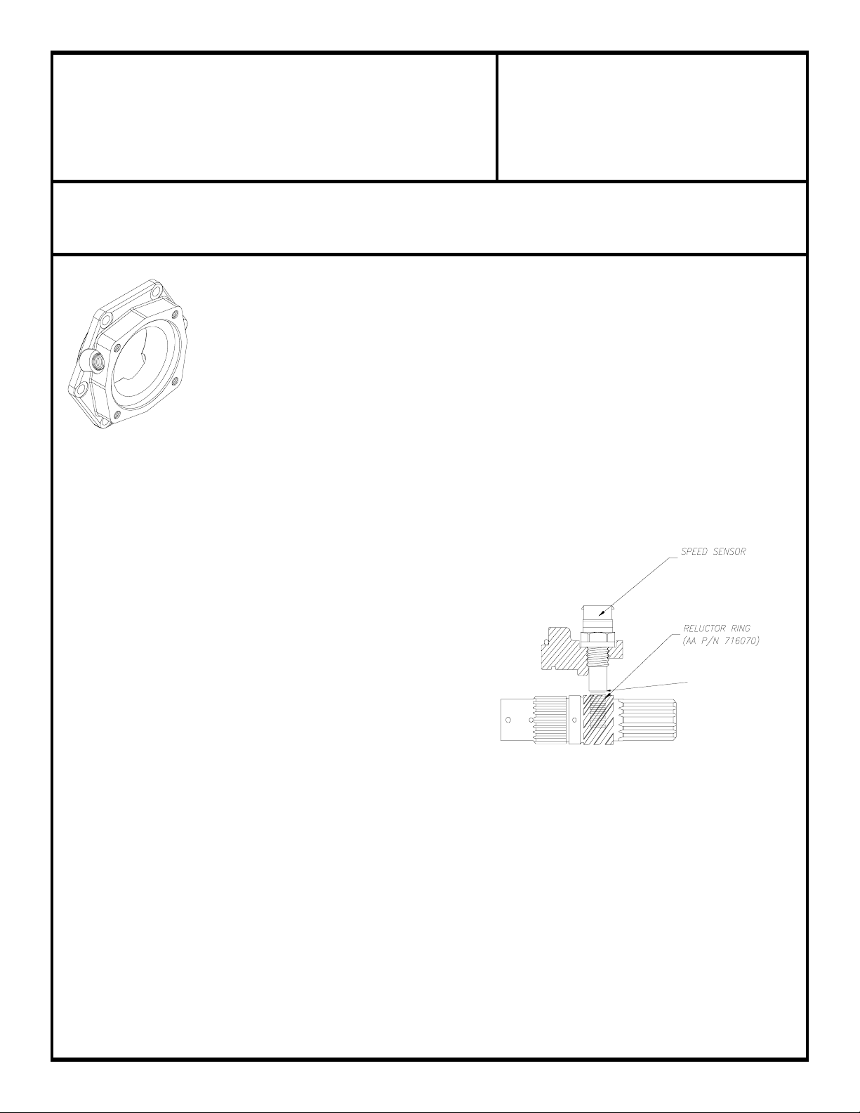
pulse system on the transmission. First is the reluctor ring.
This clamp-on reluctor ring fits over the stock governor gear on
the supplied output shaft. It creates 40 pulses for each revolution
of the output shaft for the drivetrain control module. We have
provided two reluctor sensor locations to choose from in the adapter.
The hole not being used will need to be plugged with the brass plug
provided.
SPECIAL NOTE: The components packaged in this kit have been assembled and machined for specific types of conversions. Modifications to any of the
components will void any possible warranty or return privileges. If you do not fully understand the modifications or changes that will be required to complete
your conversion, we strongly recommend that you contact our sales department for more information. This Instruction Sheet is only to be used for the assembly
of Advance Adapter components. We recommend that a service manual pertaining to your vehicle be obtained for specific torque vales, wiring diagrams and
other related equipment. These manuals are normally available at automotive dealerships and parts stores.
Page 2
ADVANCE ADAPTERS, INC. P/N: 50-0430
P.O. Box 247, 4320 Aerotech Center Way New Kit: (02/03)
Paso Robles, CA 93447 PAGE: 2 OF 4
Telephone: (800) 350-2223 Fax: (805) 238-4201 Page Rev. Date: 05-01-13
GM 4L60E TO NP TRANSFER CASES (23SPL)
Pulse Generator Installation:
Slide the reluctor ring over the 4L60E shaft installed in the transmission. Push the ring
completely onto the shaft until it bottoms out. Lightly snug the set screws for a "dry run". Trial
fit the 51-0405 adapter plate onto the back of the 4L60E transmission using two of the supplied
bolts. With the adapter bolted on the back of the transmission, install the 300619 reluctor sensor
into the adapter casting. The 300619 sensor should line up over the teeth of the reluctor clamp.
(If the clamp-on ring is not completely bottomed out, this may cause a miss-alignment with the
sensor). When you have confirmed the correct location of the shaft, remove the adapter housing.
Make sure you do not disturb the position of the clamp on the shaft. With the clamp now exposed,
tighten the set screw on the clamp.
recommended on these set screws.
You should now be ready for final installation of the 51-0405 casting. RTV Blue Silicone should be used to seal adapter
51-0405 to your 4L60E transmission. Use all of the supplied bolts for the casting and torque according to factory specs.
Next, screw the 300619 sensor completely into the 51-0405 casting. Be careful not to force
this sensor once it has contacted the shaft. Slowly back the sensor out of the hole and
with a feeler gauge. Check the gap between the sensor and the reluctor ring. This
gap should be around 0.010" to 0.012". Once 0.010" to 0.012" clearance is
obtained, Loctite the sensor into position.
(One piece reluctor, bolt torque 10 ft-lbs.) Loctite is highly
P/N 300619
You are now ready to bolt your conversion adapter to the 51-0405 kit.
NOTE: On a few applications, customers have not positioned the
clamp in the correct position which has caused interference
with the input shaft in the transfer case. If you try bolting the
conversion adapter up to the 51-0405 and find interference,
the spud shaft may be hitting the clamp on the reluctor.
ASSEMBLY PROCEDURES:
1. Trial fit the 51-6800 adapter on the already installed 51-0405 casting. Check to see that the castings seat flush against
each other. Use two of the supplied bolts to temporarily hold these together.
2. Trial fit the transfer case to the adapter and transmission. Check for spline engagement and shaft depth into the input
coupler of the transfer case. If the transfer case does not mate flush against the casting, DO NOT DRAW IT
TOGETHER WITH THE FASTENERS. SEVERE DAMAGE WILL OCCUR. This is not normally found when
replacing an AX15 manual transmission. If interference is detected, the output shaft must be shortened to a flush stickout
with reference to the casting. On Automatic Torqueflite 999 applications where the factory output shaft does not
protrude beyond the stock adapter, the will need shaft modifications. Cutting the shaft will require a cut off disc
to cut the outer edges, and a hacksaw to cut through the center. If you are unsure about cutting, please call us toll free
at 1-800 350-2223. If you do not have the ability to cut your shaft, a 1" spacer is available (Part No. 51-0404).
4. Remove the 51-6800 adapter, then press the seal into the casting with the open side toward the transmission.
SPECIAL NOTE: The components packaged in this kit have been assembled and machined for specific types of conversions. Modifications to any of the
components will void any possible warranty or return privileges. If you do not fully understand the modifications or changes that will be required to complete
your conversion, we strongly recommend that you contact our sales department for more information. This Instruction Sheet is only to be used for the assembly
of Advance Adapter components. We recommend that a service manual pertaining to your vehicle be obtained for specific torque vales, wiring diagrams and
other related equipment. These manuals are normally available at automotive dealerships and parts stores.
A .010"-.012" GAP
Page 3

ADVANCE ADAPTERS, INC. P/N: 50-0430
P.O. Box 247, 4320 Aerotech Center Way New Kit: (02/03)
Paso Robles, CA 93447 PAGE: 3 OF 4
Telephone: (800) 350-2223 Fax: (805) 238-4201 Page Rev. Date: 02-05-03
GM 4L60E TO NP TRANSFER CASES (23SPL)
5. For final installation, install the rubber o-ring on the transmission side of the adapter. A thin bead of silicone should be
applied as a sealant.
6. The four 3/8"-16 x 1-3/4" Socket Head Cap Screws are then used to secure the casting to the transmission.
7. Two rotations are provided on the casting. Choose the rotation that best suits your application.
8. Studs and nuts are provided for securing the transfer case.
9. Two of the positions on the rotation will require removal of two studs from the transfer case and substitution by the
two 3/8"-16 x 1-1/4" Socket Head Cap Screws. This is due to lack of wrench clearance around the casting.
10. Use silicone sealant on both sides of the transfer case gasket. Use Loctite on all bolts.
Notes:
Again, when installing the new transfer case adapter, make sure that the transfer case input sleeve and the output shaft do
not bottom out. We have found on occasion that a transmission output shaft may be slightly longer than we have allowed for;
and when coupling into the transfer case, we find a small amount of interference. The adapter housing and shaft must be
assembled to the back of the transmission without interference. DO NOT FORCE THE NEW TAILHOUSING ONTO THE
TRANSMISSION. If assistance is needed, please feel free to call us on our toll free number, 1-800 350-2223.
This adapter can be used on either Jeep Wranglers 1987 & newer or Jeep Cherokees 1984 & newer. The only difference
is the transfer case shifter linkage. The adapter combination is 2.875" thick and will provide an overall transmission assembly
length of 24-7/8". On conversions using the 4L60E, you can anticipate driveshaft modifications. The adapter crossmember
support is designed around the replacement of a
manual transmission. If you are replacing an
automatic transmission, you will find that the
crossmember support will hang too far down
when it is bolted to the bottom of our new adapter
housing. We suggest that you purchase a crossmember support from the manual transmission
application to simplify this problem.
The transfer case shift linkage is mounted in two
different designs. Jeep Wranglers 1987-96 will
require shifter bracket No. 715523, while Cherokee conversions will require shifter bracket No.
715524. Some applications will require the pur-
chase of a stock Jeep bracket, #53004280. This
is the most universal bracket for YJ Wranglers.
TJ conversions will need to space the body
bracket to use the stock linkage.
SPECIAL NOTE: The components packaged in this kit have been assembled and machined for specific types of conversions. Modifications to any of the
components will void any possible warranty or return privileges. If you do not fully understand the modifications or changes that will be required to complete
your conversion, we strongly recommend that you contact our sales department for more information. This Instruction Sheet is only to be used for the assembly
of Advance Adapter components. We recommend that a service manual pertaining to your vehicle be obtained for specific torque vales, wiring diagrams and
other related equipment. These manuals are normally available at automotive dealerships and parts stores.
Page 4

ADVANCE ADAPTERS, INC. P/N: 50-0430
P.O. Box 247, 4320 Aerotech Center Way New Kit: (02/03)
Paso Robles, CA 93447 PAGE: 4 OF 4
Telephone: (800) 350-2223 Fax: (805) 238-4201 Page Rev. Date: 02-11-11
GM 4L60E TO NP TRANSFER CASES (23SPL)
51-6800
NOTES:
1. Before assembling the new transmission shaft into your 4L60E, you must verify the spline size of the new shaft and the
input gear of the new process transfer case. The shaft is available in either 21 or 23 spline tooth count.
2. Be sure that the adapter shaft and T/C input gear do not bottom out prior to the adapter meeting flush with the
transmission. Some models may require the output shaft to be shortened.
3. The adapter has provisions for a new seal (NAT #456057). The outside diameter is 3.75" and the inside diameter is
1.937". The seal must be installed with the open side towards the transmission.
SPECIAL NOTE: The components packaged in this kit have been assembled and machined for specific types of conversions. Modifications to any of the
components will void any possible warranty or return privileges. If you do not fully understand the modifications or changes that will be required to complete
your conversion, we strongly recommend that you contact our sales department for more information. This Instruction Sheet is only to be used for the assembly
of Advance Adapter components. We recommend that a service manual pertaining to your vehicle be obtained for specific torque vales, wiring diagrams and
other related equipment. These manuals are normally available at automotive dealerships and parts stores.
 Loading...