

Page 1
ADVANCE ADAPTERS INC. P/N: SUZUKI
P.O. Box 247, 4320 Aerotech Center Way New Item: (09/09)
Paso Robles, CA 93447 PAGE 1 OF 11
Telephone: (800) 350-2223 Fax: (805) 238-4201 Page Rev. Date: 09-09-09
SUZUKI GEARS KIT NUMBERS
48-4160 / 48-4900 /48-6400
KIT CONSISTS OF:
No. Qty. Part
1. 1 GEAR SET OF 3 SETS AND SHAFT WITH GEAR
2. 1 CLUSTER SHAFT
3. 2 CLUSTER THRUST WASHERS
4. 2 CAGED NEEDLE BEARINGS
5. 1 GASKET SET
6. 3 SEALS
7. 1 O-RING
Suggested tools:
Ratchet, 12mm, 14mm & 28mm sockets
Air impact gun
Hammer
Grinder on some gear sets
Needle nose pliers
3/16" punch
Snap ring pliers
Gasket scraper
6mm Allen wrench
Straight screwdriver
Crescent wrench
RTV silicon
Bearing grease
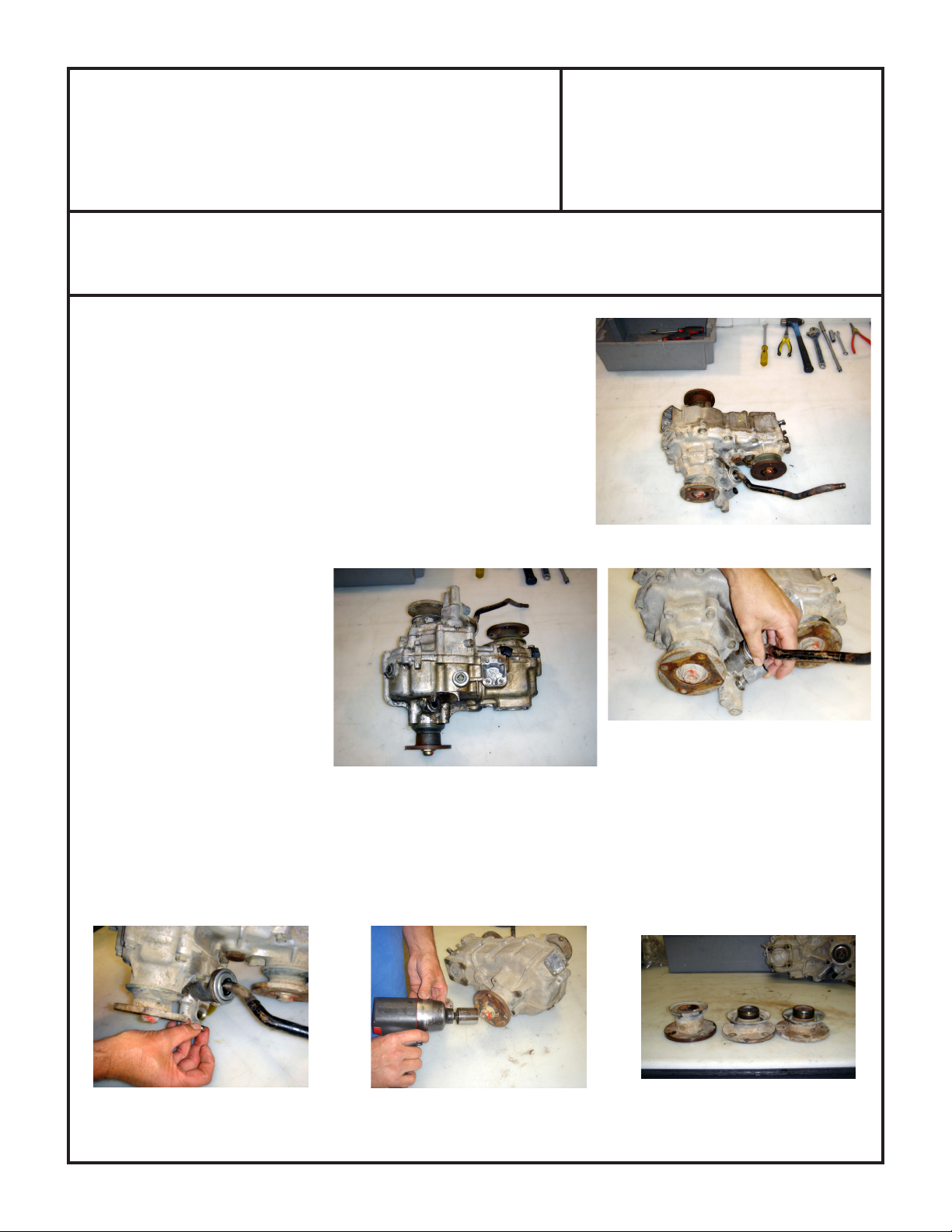
1. Drain oil from transfer case and remove the transfer case from the vehicle.
2. Remove the 4WD indicator switch.
3. Turn the transfer case over and collect the 4WD indicator ball as it falls out of the indicator hole. This is a larger
ball than the balls removed later.
4. Use the 28mm socket and remove all three flange yokes, label them for correct re-installation.
SPECIAL NOTE: The components packaged in this kit have been assembled and machined for specific type of conversions. Modifications to any of the components will
void any possible warranty or return privileges. If you do not fully understand modifications or changes that will be required to complete your conversion, we strongly recommend
that you contact our sales department for more information. This instruction sheet is only to be used for the assembly of Advance Adapter components. We recommend that a
service manual pertaining to your vehicle be obtained for specific torque values, wiring diagrams and other related equipment. These manuals are normally available at automotive
dealerships and parts stores.
Page 2
ADVANCE ADAPTERS INC. P/N: SUZUKI
P.O. Box 247, 4320 Aerotech Center Way New Item: (09/09)
Paso Robles, CA 93447 PAGE 2 OF 11
Telephone: (800) 350-2223 Fax: (805) 238-4201 Page Rev. Date: 09-09-09
SUZUKI GEARS KIT NUMBERS
48-4160 / 48-4900 /48-6400
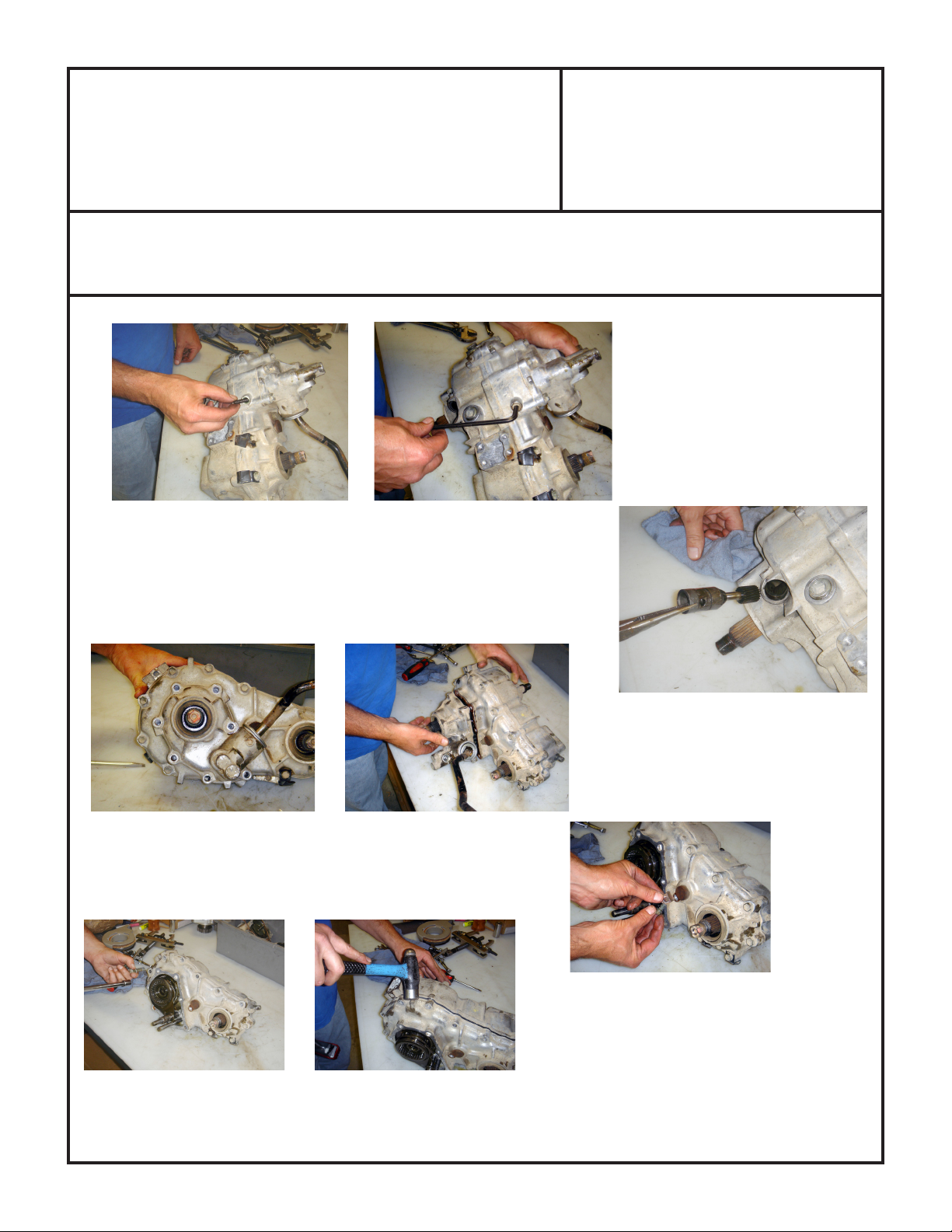
5. On the bottom of the transfer case, remove the 6mm detent plug.
6. Remove the detent spring and ball by flipping the T/C over.
7. Remove the speedometer bolt and speedometer housing.
8. Remove the 7 bolts holding the front housing to the case. Please note bolt
locations.
9. Remove the front housing.
10. Remove the cluster shaft locking tab.
11. Remove the 11 bolts on the main case assembly.
12. Using a small hammer, tab the two case halves apart.
SPECIAL NOTE: The components packaged in this kit have been assembled and machined for specific type of conversions. Modifications to any of the components will
void any possible warranty or return privileges. If you do not fully understand modifications or changes that will be required to complete your conversion, we strongly recommend
that you contact our sales department for more information. This instruction sheet is only to be used for the assembly of Advance Adapter components. We recommend that a
service manual pertaining to your vehicle be obtained for specific torque values, wiring diagrams and other related equipment. These manuals are normally available at automotive
dealerships and parts stores.
Page 3
ADVANCE ADAPTERS INC. P/N: SUZUKI
P.O. Box 247, 4320 Aerotech Center Way New Item: (09/09)
Paso Robles, CA 93447 PAGE 3 OF 11
Telephone: (800) 350-2223 Fax: (805) 238-4201 Page Rev. Date: 09-09-09
SUZUKI GEARS KIT NUMBERS
48-4160 / 48-4900 /48-6400
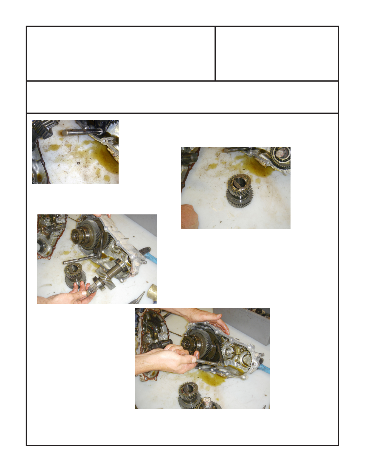
13. As the case halves come apart, be sure to catch the small steel ball that will
need to be reinstalled later.
14. Remove the cluster gear and thrust washers from the rear housing.
15. Remove the input gear/shaft and bearings.
16. Remove the cluster pin and needle bearings.
17. Remove the shift fork assembly.
SPECIAL NOTE: The components packaged in this kit have been assembled and machined for specific type of conversions. Modifications to any of the components
will void any possible warranty or return privileges. If you do not fully understand modifications or changes that will be required to complete your conversion, we
strongly recommend that you contact our sales department for more information. This instruction sheet is only to be used for the assembly of Advance Adapter
components. We recommend that a service manual pertaining to your vehicle be obtained for specific torque values, wiring diagrams and other related equipment.
These manuals are normally available at automotive dealerships and parts stores.
Page 4
ADVANCE ADAPTERS INC. P/N: SUZUKI
P.O. Box 247, 4320 Aerotech Center Way New Item: (09/09)
Paso Robles, CA 93447 PAGE 4 OF 11
Telephone: (800) 350-2223 Fax: (805) 238-4201 Page Rev. Date: 09-09-09
SUZUKI GEARS KIT NUMBERS
48-4160 / 48-4900 /48-6400
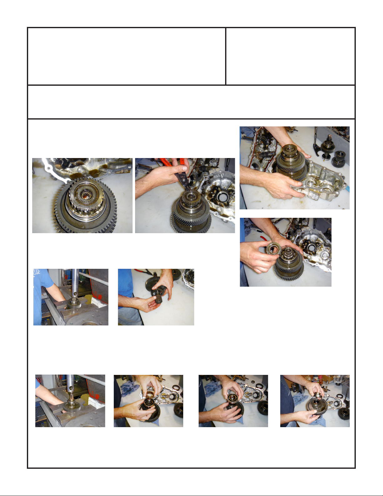
18. Remove the output shaft and gear assembly from the rear housing.
19. Remove the snap ring from the end of the output shaft.
20. Remove the gear.
21. Using a press, press the output shaft through the bearing.
22. Remove the bearing, gear spacer & high speed gear.
23. Under the gear is a caged needle bearing and a shifter hub that must also be removed.
24. Turn the shaft assembly over and press the low speed gear off the shaft. The bearing keeper bearing speedometer
gear and gear spacer will be removed first. Stack these components as they come off to aid in re-assembly.
SPECIAL NOTE: The components packaged in this kit have been assembled and machined for specific type of conversions. Modifications to any of the components
will void any possible warranty or return privileges. If you do not fully understand modifications or changes that will be required to complete your conversion, we
strongly recommend that you contact our sales department for more information. This instruction sheet is only to be used for the assembly of Advance Adapter
components. We recommend that a service manual pertaining to your vehicle be obtained for specific torque values, wiring diagrams and other related equipment.
These manuals are normally available at automotive dealerships and parts stores.
Page 5

ADVANCE ADAPTERS INC. P/N: SUZUKI
P.O. Box 247, 4320 Aerotech Center Way New Item: (09/09)
Paso Robles, CA 93447 PAGE 5 OF 11
Telephone: (800) 350-2223 Fax: (805) 238-4201 Page Rev. Date: 09-09-09
SUZUKI GEARS KIT NUMBERS
48-4160 / 48-4900 /48-6400
25. Clean the caged needle bearing that was under this gear and re-install on to the shaft with some bearing grease.
Now install the new low speed gear on to the shaft. Install the gear spacer, the speedometer gear, bearing and
bearing collar. The speedometer gear and bearing are a press fit.
26. Flip the shaft back over and re-install the shifter slider and the high speed needle bearing onto the shaft. Use bearing
grease on the needle bearing and then install the new high speed gear.
27. Re-install the gear spacer and press the bearing back in place. The spur gear and snap ring can then be re-installed.
SPECIAL NOTE: The components packaged in this kit have been assembled and machined for specific type of conversions. Modifications to any of the components
will void any possible warranty or return privileges. If you do not fully understand modifications or changes that will be required to complete your conversion, we
strongly recommend that you contact our sales department for more information. This instruction sheet is only to be used for the assembly of Advance Adapter
components. We recommend that a service manual pertaining to your vehicle be obtained for specific torque values, wiring diagrams and other related equipment.
These manuals are normally available at automotive dealerships and parts stores.
Page 6

ADVANCE ADAPTERS INC. P/N: SUZUKI
P.O. Box 247, 4320 Aerotech Center Way New Item: (09/09)
Paso Robles, CA 93447 PAGE 6 OF 11
Telephone: (800) 350-2223 Fax: (805) 238-4201 Page Rev. Date: 09-09-09
SUZUKI GEARS KIT NUMBERS
48-4160 / 48-4900 /48-6400
28. The input shaft/gear will now need the bearings removed and installed on the new shaft/gear. A press is usually
needed to remove and install the bearings.
SPECIAL NOTE: The components packaged in this kit have been assembled and machined for specific type of conversions. Modifications to any of the components
will void any possible warranty or return privileges. If you do not fully understand modifications or changes that will be required to complete your conversion, we
strongly recommend that you contact our sales department for more information. This instruction sheet is only to be used for the assembly of Advance Adapter
components. We recommend that a service manual pertaining to your vehicle be obtained for specific torque values, wiring diagrams and other related equipment.
These manuals are normally available at automotive dealerships and parts stores.
Page 7

ADVANCE ADAPTERS INC. P/N: SUZUKI
P.O. Box 247, 4320 Aerotech Center Way New Item: (09/09)
Paso Robles, CA 93447 PAGE 7 OF 11
Telephone: (800) 350-2223 Fax: (805) 238-4201 Page Rev. Date: 09-09-09
SUZUKI GEARS KIT NUMBERS
48-4160 / 48-4900 /48-6400
29. Temporarily install the cluster gear into the case halves to check for gear and case clearance. Use a marking pen
to make the case for clearances. With a grinder modify the case as necessary to fit the gear.
30. Inspect the front shifter housing seal and o-ring for wear.
31. Remove the yoke seals from the housings and replace them with the new seals included in the kit.
32. Install the steel ball in the center housing as shown and adjust the shift rail until the ball drops into the slot.
SPECIAL NOTE: The components packaged in this kit have been assembled and machined for specific type of conversions. Modifications to any of the components
will void any possible warranty or return privileges. If you do not fully understand modifications or changes that will be required to complete your conversion, we
strongly recommend that you contact our sales department for more information. This instruction sheet is only to be used for the assembly of Advance Adapter
components. We recommend that a service manual pertaining to your vehicle be obtained for specific torque values, wiring diagrams and other related equipment.
These manuals are normally available at automotive dealerships and parts stores.
Page 8

ADVANCE ADAPTERS INC. P/N: SUZUKI
P.O. Box 247, 4320 Aerotech Center Way New Item: (09/09)
Paso Robles, CA 93447 PAGE 8 OF 11
Telephone: (800) 350-2223 Fax: (805) 238-4201 Page Rev. Date: 09-09-09
SUZUKI GEARS KIT NUMBERS
48-4160 / 48-4900 /48-6400
33. Slide the high/low shift rail onto the output gear assembly.
34. Slide the gear assembly into the center housing.
35. Install the front shift collar onto the shift fork.
36. Tap the output assembly into place using a rubber hammer
37. Apply grease to the face of the thrust washer and place the thrust washer to the center housing making sure the
washer tab fits to the notch in the housing.
SPECIAL NOTE: The components packaged in this kit have been assembled and machined for specific type of conversions. Modifications to any of the components
will void any possible warranty or return privileges. If you do not fully understand modifications or changes that will be required to complete your conversion, we
strongly recommend that you contact our sales department for more information. This instruction sheet is only to be used for the assembly of Advance Adapter
components. We recommend that a service manual pertaining to your vehicle be obtained for specific torque values, wiring diagrams and other related equipment.
These manuals are normally available at automotive dealerships and parts stores.
Page 9

ADVANCE ADAPTERS INC. P/N: SUZUKI
P.O. Box 247, 4320 Aerotech Center Way New Item: (09/09)
Paso Robles, CA 93447 PAGE 9 OF 11
Telephone: (800) 350-2223 Fax: (805) 238-4201 Page Rev. Date: 09-09-09
SUZUKI GEARS KIT NUMBERS
48-4160 / 48-4900 /48-6400
38. Install the O-ring on the cluster pin and slide the bearings and spacer on the cluster pin.
39. Apply grease to the cluster bearings and slide the cluster gear onto the shaft assembly. Take the cluster assembly
having the pin flush with the large end of the gear and slide it into position in the case. Then push the pin from
the small end of the cluster to capture the thrust washer and to index into the case.
40. Slide the input gear assembly into place.
41. Apply grease into the rear housing and to the other thrust washer assembly,
holding the washer in place.
SPECIAL NOTE: The components packaged in this kit have been assembled and machined for specific type of conversions. Modifications to any of the components
will void any possible warranty or return privileges. If you do not fully understand modifications or changes that will be required to complete your conversion, we
strongly recommend that you contact our sales department for more information. This instruction sheet is only to be used for the assembly of Advance Adapter
components. We recommend that a service manual pertaining to your vehicle be obtained for specific torque values, wiring diagrams and other related equipment.
These manuals are normally available at automotive dealerships and parts stores.
Page 10

ADVANCE ADAPTERS INC. P/N: SUZUKI
P.O. Box 247, 4320 Aerotech Center Way New Item: (09/09)
Paso Robles, CA 93447 PAGE 10 OF 11
Telephone: (800) 350-2223 Fax: (805) 238-4201 Page Rev. Date: 09-09-09
SUZUKI GEARS KIT NUMBERS
48-4160 / 48-4900 /48-6400
42. Apply silicone to the case haves and install the gasket. Slide the case two haves together making sure the thrust
washer stays in place. Once the cases are aligned and slide together, install the 11 bolts back to there original
location.
42A. You may have to twist the
cluster pin in the case to install
the locking tab.
43. Apply silicone to the front housing and apply the gasket. Bolt the housing to the case making sure the correct bolt
placement.
SPECIAL NOTE: The components packaged in this kit have been assembled and machined for specific type of conversions. Modifications to any of the components
will void any possible warranty or return privileges. If you do not fully understand modifications or changes that will be required to complete your conversion, we
strongly recommend that you contact our sales department for more information. This instruction sheet is only to be used for the assembly of Advance Adapter
components. We recommend that a service manual pertaining to your vehicle be obtained for specific torque values, wiring diagrams and other related equipment.
These manuals are normally available at automotive dealerships and parts stores.
Page 11

ADVANCE ADAPTERS INC. P/N: SUZUKI
P.O. Box 247, 4320 Aerotech Center Way New Item: (09/09)
Paso Robles, CA 93447 PAGE 11 OF 11
Telephone: (800) 350-2223 Fax: (805) 238-4201 Page Rev. Date: 09-09-09
SUZUKI GEARS KIT NUMBERS
48-4160 / 48-4900 /48-6400
44. Install the yokes on to the transfer case and stake them to the shafts. The rear yoke is the taller yoke and is different
than the other two.
43. Reinstall the steel ball in the bottom of the case followed by the spring and the detent plug.
44. Install the speedometer drive unit and the retaining bolt.
45. Install the 4WD indicator ball and the switch.
46. Install the transfer case back into the vehicle, install the shifter handle and fill with the 80/90W GL5 gear oil.
SPECIAL NOTE: The components packaged in this kit have been assembled and machined for specific type of conversions. Modifications to any of the components
will void any possible warranty or return privileges. If you do not fully understand modifications or changes that will be required to complete your conversion, we
strongly recommend that you contact our sales department for more information. This instruction sheet is only to be used for the assembly of Advance Adapter
components. We recommend that a service manual pertaining to your vehicle be obtained for specific torque values, wiring diagrams and other related equipment.
These manuals are normally available at automotive dealerships and parts stores.
 Loading...