

Page 1

ADVANCE ADAPTERS INC. P/N: 477021
P.O. Box 247, 4320 Aerotech Center Way New Item: (12/01)
Paso Robles, CA 93447 PAGE 1 OF 14
Telephone: (800) 350-2223 Fax: (805) 238-4201 Page Rev. Date: 02-23-11
TOYOTA LOW GEAR 4.7:1 21 SPLINE
For Gear-Driven T ransfer Cases ONLY
The installation of this gear set requires you to almost completely disassemble the transfer case. We have provided
illustrative assembly and disassembly instructions. If your transfer case is in need of a rebuild, now would be the time
to do it.
Here are a couple of points to keep in mind that will make the installation much easier if you've never disassembled a
Toyota transfer case:
1.) Keep all bolts separated into groups as you remove them and label their container.
2.) Keep all small parts in separate containers and label as to location and origin.
3.) Make sure you have plenty of time and a clean, spacious area to perform the installation.
4.) You might want to have a qualified machine shop remove and install the bearings and seals on the new gears,
input shaft and in the case.
5.) The Trail Tamer instructions (in TT001) are to be used as a guide. The official Toyota shop manual is strongly
recommended for your particular application. See Pages 3 & 4 on this instruction sheet to identify your
style transfer case & see what modifications are needed to your transfer case.
TOOLS YOU WILL NEED:
12mm, 14mm and 30mm Metric sockets and ratchet driver
6mm Allen (hex) head wrench
Snap-ring pliers
3/16" (4mm) drift / roll pin punch
Plastic soft blow hammer
Bearing / gear puller with long fingers
Bearing press device
Die grinder
SPECIAL NOTE: The components packaged in this kit have been assembled and machined for specific type of conversions. Modifications to any of the components will
void any possible warranty or return privileges. If you do not fully understand modifications or changes that will be required to complete your conversion, we strongly recommend
that you contact our sales department for more information. This instruction sheet is only to be used for the assembly of Advance Adapter components. We recommend that a
service manual pertaining to your vehicle be obtained for specific torque values, wiring diagrams and other related equipment. These manuals are normally available at automotive
dealerships and parts stores.
Page 2

ADVANCE ADAPTERS INC. P/N: 477021
P.O. Box 247, 4320 Aerotech Center Way New Item: (12-01)
Paso Robles, CA 93447 PAGE 2 OF 14
Telephone: (800) 350-2223 Fax: (805) 238-4201 Page Rev. Date: 02-23-11
TOYOTA LOW GEAR 4.7:1 21 SPLINE
For Gear-Driven T ransfer Cases ONLY
SNAP RING LIST:
This is a list of Toyota snap rings that may be needed for your installation should your stock snap rings
become distorted during disassembly or assembly. These snap rings are stock Toyota parts and can be
obtained at a Toyota parts dealership. Advance Adapters does not carry these components.
36221C
90520-28242 1.50-1.55mm
90520-28248 1.60-1.65mm
36223A
90520-30215 2.10mm
90520-30217 2.20mm
36231F
90520-71221 1.65mm with 71.1mm ID
90520-36250 2.40-2.45mm
90520-36251 2.45-2.50mm
90520-36252 2.50-2.55mm
90520-36253 2.55-2.60mm
90520-36254 2.60-2.65mm
90520-36255 2.65-2.70mm
36212D
90520-72001 1.45mm
90520-72002 1.50mm
90520-72003 1.55mm
90520-72004 1.60mm
90520-72005 1.65mm
SPECIAL NOTE: The components packaged in this kit have been assembled and machined for specific type of conversions. Modifications to any of the components will
void any possible warranty or return privileges. If you do not fully understand modifications or changes that will be required to complete your conversion, we strongly recommend
that you contact our sales department for more information. This instruction sheet is only to be used for the assembly of Advance Adapter components. We recommend that a
service manual pertaining to your vehicle be obtained for specific torque values, wiring diagrams and other related equipment. These manuals are normally available at automotive
dealerships and parts stores.
Page 3
ADVANCE ADAPTERS INC. P/N: 477021
P.O. Box 247, 4320 Aerotech Center Way New Item: (12-01)
Paso Robles, CA 93447 PAGE 3 OF 14
Telephone: (800) 350-2223 Fax: (805) 238-4201 Page Rev. Date: 02-23-11
TOYOTA LOW GEAR 4.7:1 21 SPLINE
For Gear-Driven T ransfer Cases ONLY
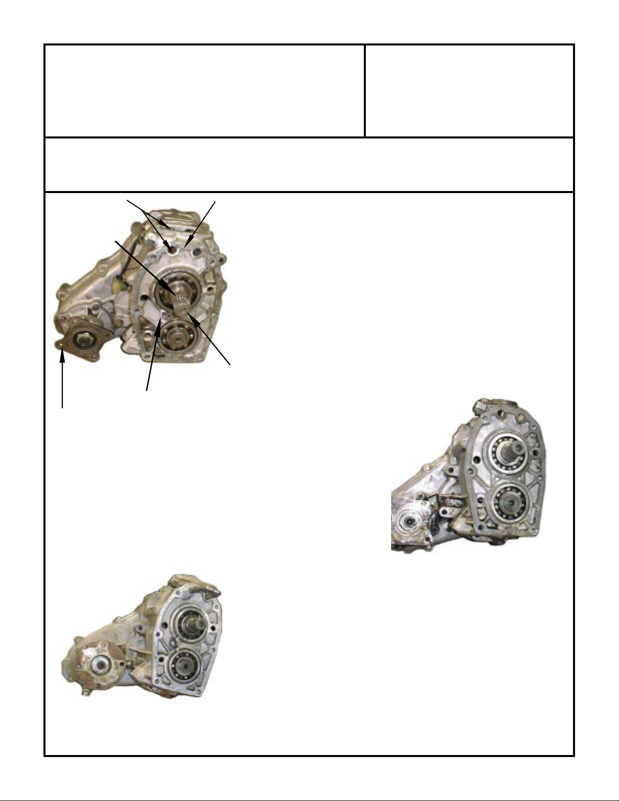
BD
1979-80 4SP TRANSFER CASE
A
E
C
Identification points on this transfer case
are the same on the transfer cases below.
A. Extended splines on input shaft.
B. Short Case (.400).
C. 8.125 Front driveline bolts.
D. Transfer case shifter in top of T-case. Short shift rails.
E. Noisy run gears (no front retainer clip).
F. 21 spline input shaft.
Modification Notes:
This transfer case will require modifications to the shift forks. Refer to Assembly
Step A-12 of the in the Toyota Truck Instruction Manual.
The transfer case reduction box may need to be relieved due to core shift. Refer
to Assembly Step A-11 of the in the Toyota Truck Instruction Manual.
F
1981 to (April) 1983 5SP TRANSFER CASE
B. Short Case (.400).
C. 8.125 Front driveline bolts.
D. Transfer case shifter in top of T-case. Short shift rails.
E. Noisy run gears (no front retainer clip).
F. 21 spline input shaft.
Modification Notes:
This transfer case will require modifications to the shift forks. Refer to
Assembly Step A-12 of the in the Toyota Truck Instruction Manual.
The transfer case reduction box may need to be relieved due to core shift.
Refer to Assembly Step A-11 of the in the Toyota Truck Instruction Manual.
1984-88 CARBURETED 5SP TRANSFER CASE
B. Tall Case (.580).
C. 10.125 Front driveline bolts.
D. Transfer case shifter in top of transmission with forward shift rails.
E. Quiet run gears (front retainer clip).
F. 21 spline input shaft.
Modification Notes:
The transfer case reduction box may need to be relieved due to core shift. Refer
to Assembly Step A-11 of the in the Toyota Truck Instruction Manual.
SPECIAL NOTE: The components packaged in this kit have been assembled and machined for specific type of conversions. Modifications to any of the components
will void any possible warranty or return privileges. If you do not fully understand modifications or changes that will be required to complete your conversion, we
strongly recommend that you contact our sales department for more information. This instruction sheet is only to be used for the assembly of Advance Adapter
components. We recommend that a service manual pertaining to your vehicle be obtained for specific torque values, wiring diagrams and other related equipment.
These manuals are normally available at automotive dealerships and parts stores.
Page 4
ADVANCE ADAPTERS INC. P/N: 477021
P.O. Box 247, 4320 Aerotech Center Way New Item: (12-01)
Paso Robles, CA 93447 PAGE 4 OF 14
Telephone: (800) 350-2223 Fax: (805) 238-4201 Page Rev. Date: 02-23-11
TTOYOTA LOW GEAR 4.7:1 21 SPLINE
For Gear-Driven T ransfer Cases ONLY
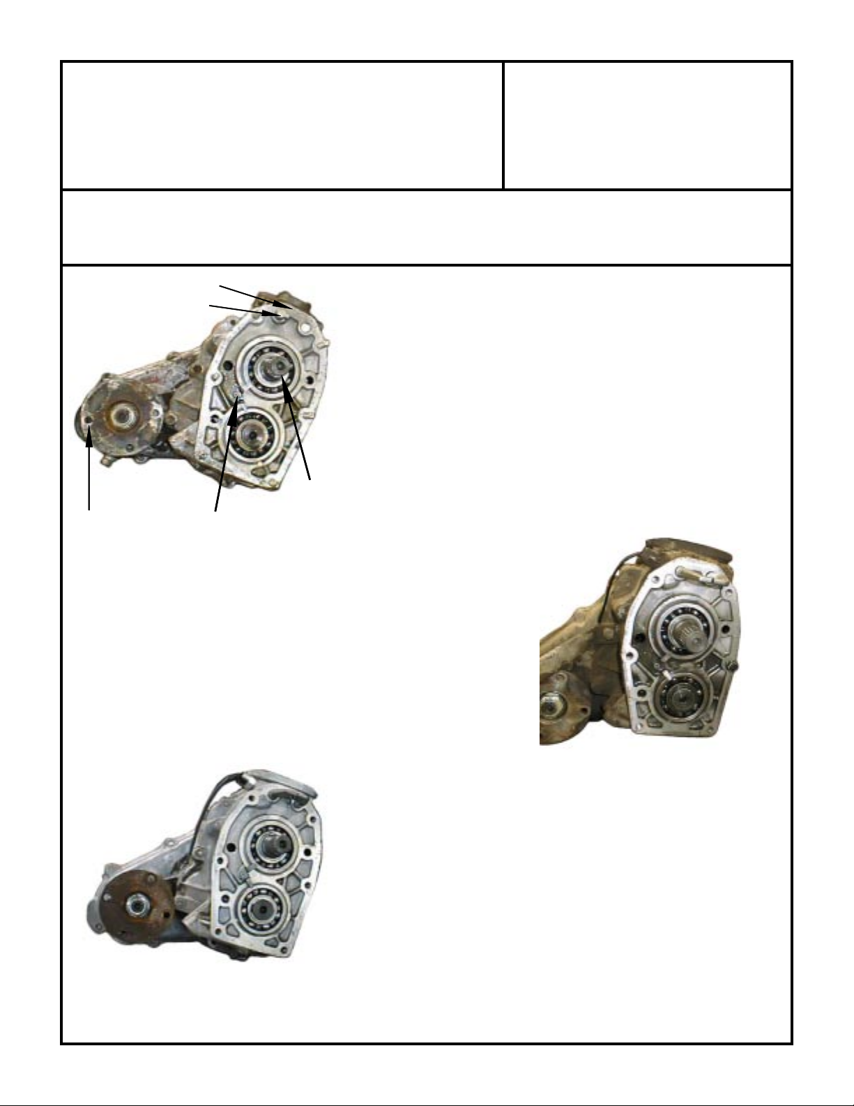
B
D
CE
Identification points on this transfer case
are the same on the transfer cases below.
1985-88 E.F.I. 5SP TRANSFER CASE
B. Tall Case (.580).
C. 10.125 Front driveline bolts.
D. Transfer case shifter in top of T-case. Short shift rails with low-range
shifter rod proturding out approximately .500.
1985 to August 1988
E. Quiet run gears (front retainer clip).
F. 21 spline input shaft.
Modification Notes:
This transfer case will require modifications to the shift forks. Refer to
Assembly Step A-12 of the in the Toyota Truck Instruction Manual.
F
The transfer case reduction box may need to be relieved due to core shift. Refer
to Assembly Step A-11 of the in the Toyota Truck Instruction Manual.
1989-95 E.F.I. 5SP TRANSFER CASE
B. Tall Case (.580)
C. 10.125 Front driveline bolts.
D. Transfer case shifter in top of transmission with forward shift rails. The
shifter rods are 1/2" shorter than the 1984-88 Carbureted T/C.
E. Quiet run gears (front retainer clip).
F. 21 spline input shaft.
Modification Notes:
The transfer case reduction box may need to be relieved due to core shift.
Refer to Assembly Step A-11 of the in the Toyota Truck Instruction Manual.
Carburated T-cases had shifter in transmission.
1986-87 TURBO E.F.I. 5SP TRANSFER CASE
1988-95 V6 5SP TRANSFER CASE
B. Tall Case (.580)
C. 10.125 Front driveline bolts.
D. Transfer case shifter in top of transmission with forward shift rails.
E. Quite run gears (front retainer clip).
F. 23 spline input shaft.
Modification Notes:
The transfer case reduction box may need to be relieved due to core shift.
Refer to Assembly Step A-11 of the in the Toyota Truck Instruction Manual.
SPECIAL NOTE: The components packaged in this kit have been assembled and machined for specific type of conversions. Modifications to any of the components
will void any possible warranty or return privileges. If you do not fully understand modifications or changes that will be required to complete your conversion, we
strongly recommend that you contact our sales department for more information. This instruction sheet is only to be used for the assembly of Advance Adapter
components. We recommend that a service manual pertaining to your vehicle be obtained for specific torque values, wiring diagrams and other related equipment.
These manuals are normally available at automotive dealerships and parts stores.
Page 5
ADVANCE ADAPTERS INC. P/N: 477021
P.O. Box 247, 4320 Aerotech Center Way New Item: (12-01)
Paso Robles, CA 93447 PAGE 5 OF 14
Telephone: (800) 350-2223 Fax: (805) 238-4201 Page Rev. Date: 02-23-11
TOYOTA LOW GEAR 4.7:1 21 SPLINE
For Gear-Driven T ransfer Cases ONLY
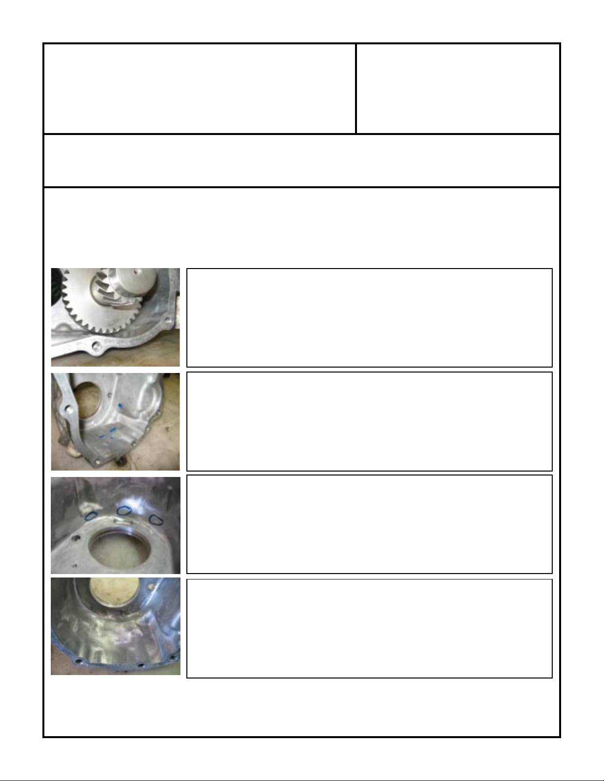
Installation Tips: For those who do not have access to a mill, here is an easy way to clearance your reduction
housing. This procedure requires only some marking fluid and a small angled grinder. This should take you about
1 hour, but remember to take your time and do it slowly. If you do not feel comfortable making these modifications,
we offer P/N 51-5911. This is a heavy duty housing that has been pre-clearanced for these gear sets.
First, test fit your new gear set into your reduction housing. You will notice that the
gears will interfere with the casting in multiple locations. Lightly tap the gear into
the casting. This will score the casting at the interference locations. Now using
marking fluid (paint pen, permanent marker, etc.), take the time to carefully mark
all locations where contact is made.
Now that all your marks have been made, it's time to start slowy removing material
from the casting. Using the grinder equipped with a 50 grit disc, begin to work away
at your marked areas. Remember to take mental note of how much each section
of the casting was contacting the gear. Take special care at this point not to remove
too much material.
After the marked areas have been ground away, go ahead and re-test fit the gears
back into the housing. Make sure to rotate the gear and that it has 360 degree
clearance with all areas of the housing. At this point, it may be necessary to re mark
areas where the gear is still contacting the housing. Repeating this procedure a few
times will insure proper fit and you will avoid the possibility of grinding a hole through
the casting.
With all the grinding done, test fit the gear set one last time making sure that every
thing spins freely and that there are no hang ups or tight spots. In addition to the
case, also remember that the shift rails will require some modifications due to gear
interference. This would be the optimal time to complete this procedure as well.
Make sure that the shift detents are installed to insure proper shift location for
modifications to be made.
SPECIAL NOTE: The components packaged in this kit have been assembled and machined for specific type of conversions. Modifications to any of the components
will void any possible warranty or return privileges. If you do not fully understand modifications or changes that will be required to complete your conversion, we
strongly recommend that you contact our sales department for more information. This instruction sheet is only to be used for the assembly of Advance Adapter
components. We recommend that a service manual pertaining to your vehicle be obtained for specific torque values, wiring diagrams and other related equipment.
These manuals are normally available at automotive dealerships and parts stores.
Page 6

TOYOTA TRANSFER CASE
ASSEMBLY & DISASSEMBLY PROCEDURES
These gears are ideal for the avid Toyota Truck rock crawler. These gears are designed for the Toyota Truck gear-driven transfer
case. Depending on the model of your transfer case, some additional modifications may be required. Please refer to the Transfer
Case information section for proper transfer case identification and possible modifications.
The installation of the Toyota gear sets requires you to almost completely disassemble the transfer case. We have provided
illustrative disassembly and assembly instructions to assist you. These instructions are to be used as a guide. The official Toyota
shop manual is strongly recommended for additional information. If your transfer case is in need of a rebuild, now would be the
time to do it.
DISASSEMBLY
(Step D-1)
(1)
The transfer case must be in 2WD High before
starting the disassembly procedures.
nut with a 30mm socket and then remove the flange.
(Step D-2)
(2) Remove the 7 bolts that retain the rear extension housing
with a 14mm metric socket.
a separate container. This will reduce the chances of
placing the bolts in the wrong location on reassembly.
(Step D-3)
(3) With the rear extension
housing removed, you
will see the oil pump
and speedometer drive
gears. Slide the gears
off of the rear output
shaft. Take note of the
orientation of the oil
pump and the speedometer gear.
the speedometer drive gear. Make sure you store it in a
bag or some other kind of container. These little parts can
walk away.
NOTE: There is a small ball bearing under
HINT: Keep these bolts in
Remove the
(Step D-4)
(4) Remove the rear output shaft bearing.
(Step D-5)
(5) Remove outer bearing C-clip by reaching inside case and
pushing up on gear, while lightly tapping on the case with
a plastic soft blow mallet.
(Step D-6)
(6) Remove the 10 bolts retaining the rear case cover with a
14mm socket. Retain these separately to avoid any confusion during assembly.
Note their location before removal!
Some bolts are different lengths.
Page 7

(Step D-7)
(7) Pull case off. Remove the two lubrication tubes located on
either side of the main shaft.
Note their orientation!
(Step D-11)
(11)Remove the thick spacer found behind the front wheel drive
gear and be aware of the small ball bearing underneath it.
(Step D-8)
(8) Using a 3/16" (4mm) punch, drive the roll pin out that holds
the front wheel drive shift fork.
(Step D-9)
(9) Slide the fork and clutch sleeve off the shift rail.
(Step D-10)
(10)Remove the front wheel drive gear and it's caged needle
roller bearing assembly.
(Step D-12)
(12)Use a 12mm socket to remove the four bolts that retain the
shift fork cover. With a 5mm Allen wrench, remove the shift
detent screw plugs found on both sides of the case.
(Step D-13)
(13)With the screw plugs removed, the shift ball and spring
assemblies can be removed from both sides.
(Step D-14)
(14)Drive the roll pin out that
retains the high/low shift
fork using a 3/16" (4mm)
punch. Occasionally the
pin will fall into the case.
Don't worry. You will be
able to retrieve the pin
later. On 1979-83 and
1985-88 fuel injected
model transfer cases,
DO NOT REMOVE roll
pin.
Page 8

This interlock pin is located between the two
shift rail detent assembly
chambers.
(Step D-15)
(15)Remove the shift rails,
being careful not to
lose the interlock pin
that might fall out.
(Step D-16)
(16)Remove the 4WD in-
dicator switch with a
22mm wrench.
(Step D-19)
(19)Remove the high/low shift fork
with the clutch sleeve and
needle bearing from the input
shaft.
(Step D-20)
(20)Here are the gears that you will be replacing with the new
Trail Tamer set.
(Step D-17)
(17)Remove the interlock
pin from the shifter
detent chamber, if you
haven't already done
so in Step #D-15.
(Step D-18)
(18)Use a 14mm socket to remove the 4 bolts that retain the
front case to the reduction case. Split the cases. Now you
can retrieve the roll pin that might have fallen in as noted on
Step #D-14.
(Step D-21)
(21)Remove the output shaft from
the front case by removing the
4 bolts with a 12mm socket.
Remove the bearing retainer and snap ring.
(Step D-22)
(22)Remove the snap rings that retain the input shaft and
cluster gear bearings and remove the two from the case.
You might have to use a slight tap from a soft plastic
hammer to help them fall out.
Page 9

(Step D-23)
(23)Remove the low range gear by removing the snap ring that
retains the roller bearing onto the rear shaft. Press the roller
bearing off of the shaft.
ASSEMBLY
(Step D-24)
(24)Now that the roller bearing is removed, you will see a
spacer. Remove the spacer, being careful not to lose the
ball bearing underneath it. Remove the low range gear and
needle bearing. You will be replacing this gear with the new
low gear.
(Step A-1)
(1) Notice that the cluster / counter gear does not incorporate
the stock sub-gear and spring washer. These are not used!
(Step A-2)
(2) Install the cage needle bearing on the output shaft. Use
assembly lube provided in the kit!
(Step A-4)
(4) Install the ball bearing and spacer. Use a drop of assembly
lube to hold the small ball bearing in place during assembly.
(Step A-5)
(5) Reinstall the original roller bearing on the output shaft.
Note snap ring groove orientation on bearing!
(Step A-3)
(3) Install the new low range gear. Apply a small amount of
assembly lube to the caged roller bearing.
(Step A-6)
(6) Install the snap ring that retains the output shaft bearing in
place.
Page 10

(Step A-7)
(7) Install the output shaft assembly into the case. You might
have to tap it in gently with a soft plactic hammer.
(Step A-8)
(8) Install a new snap ring (provided in the kit) that holds in the
bearing for the output shaft.
4.77 cluster interference
(Step A-11)
(11) Install the cluster and input gears into the reduction case.
A slight tap from a soft plastic hammer should be all it takes to
get them seated. Note: On the 4.77 & 5.0 gears, the case must
be machined to provide
clearance for the cluster gear. On some 4.0
cluster gears, we have
found that the case will
need to be relieved due
to core shift. Spin the
cluster gear to check for
interference.
You can grind the necessary
clearance; however, it is recommended to machine the
case for this clearance. We
used a 1” coarse pitch
roughing end mill and took
approximately .050” off the
inside case wall. (We also
offer a new front housing that
has the proper gear clearance, P/N 51-5911)
(Step A-9)
(9) Install the bearing retainer into its original position. Apply
Loctite 242 and install the 4 bolts removed earlier. Torque
evenly to 13 ft./lbs.
(Step A-10)
(10)Press on the cluster / counter gear and input gear bearings.
Be sure to install new snap rings that retain the bearings
on the shafts.
(Step A-12)
(12)If your case uses the large E-clip, remove and replace with
the new C-clip (supplied in kit).
See Photo A-12a. The shift
fork/rail assembly should be test fit before proceeding with
the assembly. Some grinding on the fork rail boss may be
required to clear the larger gear. See Photo A-12b for
grinding locations.
As a final check, reinstall shift
rails/fork assembly over new
gear and temporarily install
mating case so that the shift
rails are indexed into the case.
The gear should rotate easily
with no interference. Now remove case half and go on to
Step 13.
r
New style
C-clip
supplied.
Photo A-12a
r
Discard this
E-clip.
Photo A-12b
Page 11

(Step A-13)
(13)Install new snap rings that retain the cluster / counter and
input gear assemblies in place.
(Step A-14)
(14)Install the output
shaft "pocket" needle
bearing. Apply assembly lube!
(Step A-15)
(15)Install the clutch sleeve
and the high/low shift
fork set into position.
(Step A-17)
(17)Apply Loctite 242 to the 4
bolts that secure the reduction case to the front case.
Torque them evenly to 29 foot/pounds using a 14mm
socket.
(Step A-18)
(18)Install the high/low range shift rail. Use assembly lube!
(Step A-16)
(16)Before mating the surfaces of the reduction box and the
front case, apply a
few
thin
dabs of RTV blue silicon
sealant to the new gasket that installs between them.
(Step A-19)
(19)The shifter must be in 4WD High to install the interlock pin.
Make sure it slides freely into place. Use that assembly
lube!
(Step A-20)
(20)Install the roll pin that retains the high/low shift fork in place
on the shift rail.
Page 12

(Step A-21)
(21)Notice that the cluster / counter gear does not incorporate
the stock sub-gear and spring washer. These are not used!
(Step A-22)
(22)Install the detent plugs (with Loctite 242), spring and ball
assembly on both sides of the assembly cases. This will
position the shift rails once the retaining plugs are installed. Torque the detent plugs to 9 ft./lbs. Use assembly
lube!
(Step A-25)
(25)Install the spacer onto the output shaft.
(Step A-26)
(26)Install the 2 caged needle roller bearings on the output
shaft. Use assembly lube.
(Step A-23)
(23)Apply a drop of assembly lube on the tip of the 4WD indicator
switch and install it into its original position on the reduction
case.
(Step A-24)
(24)Install the small ball bearing in the machined pocket on the
output shaft. Use a drop of assembly lube to hold it in place.
(Step A-27)
(27)Install the transfer gear onto the output shaft. Use assem-
bly lube!
(Step A-28)
(28)Before proceeding, make sure you have installed these
snap rings!
Page 13

(Step A-29)
(29)Install the shift fork and shift hub sleeve onto the output
shaft.
(Step A-30)
(30)Install the roll pin that holds the front wheel drive shift fork
in place.
(Step A-33)
(33)Install the drive gear for the speedometer onto the output
shaft. Make sure the orientation is correct. The hardened
side goes against the bearing.
(Step A-34)
(34)Install the ball bearing onto the pocket on the output shaft
using a drop of assembly lube to hold it in place. Install the
oil pump drive gear.
(Step A-31)
(31)Install the clutch hub onto the output shaft.
(Step A-32)
(32)Install the bearing onto the output shaft.
(Step A-35)
(35)Install the two lubrication tubes into the case. Note the
orientation shown in the photo above.
(Step A-36)
(36)Apply a very thin coat of silicone gasket sealant to the rear
case gasket, and position the rear case. Apply Loctite 242
to the threads and install the 10 bolts that retain the case
with a 14mm socket
loosely
. You will tighten these later,
after the centering of the case is performed in the following
procedures.
Page 14

(Step A-37)
(37)Replace the outer seal in the rear tail housing. Apply a thin
film of assembly lube to sealing lip of seal.
(Step A-38)
(38)Apply a
few thin dabs
of silicone gasket sealant to the rear tail extension gasket and
position the rear tail
extension. Apply Loctite 242 to the threads
and install loosely the
7 bolts that retain the
tail extension with a 14mm socket. You will also tighten
these later, after the centering of the case is performed.
(Step A-41)
(41)Install the speedometer drive assembly and the retainer.
(Step A-42)
(42)Apply a thin film of RTV sealant to the cover plate mating
surface. Install the 4 bolts that hold it in place and tighten
firmly.
We do not recommend using the stock gasket
in this location.
On occasion we have found this gasket
to slip out of position and cause a serious leak.
(Step A-39)
(39)Insert the rear drive shaft flange. This will center the cases
on the seals in the rear tail extension. Use assembly lube
where seal rides on driveshaft flange.
(Step A-40)
(40)Now, with the seals centered on the rear shaft, torque the
bolts to 34 ft./lbs.
(Step A-43)
(43)Clean and apply a bead of RTV black silicone sealant to
about the middle of the spline area and slide the rear drive
shaft flange into position. Install the retainer nut and torque
to 90 ft./lbs. Using a chisel and hammer, fold the lip of the
nut to lock it in place.
 Loading...