

Page 1
ADVANCE ADAPTERS INC. P/N: 300377A
P.O. Box 247, 4320 Aerotech Center Way New Item: (9/09)
Paso Robles, CA 93447 PAGE 1 OF 4
Telephone: (800) 350-2223 Fax: (805) 238-4201 Page Rev . Date: 11-07-14
JK A TLAS CONTROL MODULE
for NEW POLLAK SWITCHES
KIT CONSISTS OF:
No. Qty Part No. Description
1. 1 42R800 CONTROL MODULE KIT
KIT INCLUDES
2 8-32 SOCKET HEAD CAP SCREWS
2 8-32 NYLON LOCK NUTS
5 1/4"x1" HEAT SHRINK
1 3 WIRE DELPHI CONNECTOR
1 2 WIRE DELPHI CONNECTOR
1 0 CABLE TIE - BLACK 4"
2. 1 300378-4WD 4WD PIGTAIL
3.. 1 300378-LR LOW RANGE PIGTAIL
4. 2 300364 NEW LOW RANGE SWITCH
Introduction:
The JK control module is the only way of keeping all the stock
functions operational when upgrading to an Atlas transfer case.
This Module lights the dash lights in both high and low range as well
as the settings on the ESP when in 4WD and lockers and swaybar
disconnect on the Rubicon models. This kit is designed for the Atlas
2 speed but can be used on a 4 speed by connecting a additional
low range switch to the planetary housing and splicing that switch
into the lead from the low range switch from the Atlas case.
OPTIONAL ITEMS:
24-AEV PROGRAMER
24-40440 BULLY DOG
** Note**
2012 and Up Jeep JK Autos:
JK 2012 and newer Jeeps equipped with an automatic transmission will also require a Transmission Control Module flash to operate correctly
with the new Atlas transfer case. Jeep coded the
stock transfer case ratio of either the 2.72:1 or
the 4.0:1 into this module, and any different ratio
in the transfer case will put the vehicle into a limp
mode. A Jeep programer like a A.E.V. Procal or
the Bully Dog with the transfer case ratio option
in needed and we sell both of these programers.
Unfortunately, the Atlas 4 speed is not an option
in these newer JKs with the automatic.
The exact ratios for the Atlas are required for reprogramming the module. We round up or down
to the decimal on our ratios; however, the Jeep
computer module will accept the three places
right of the decimal. The ratios are as follows:
2.0:1 is exactly 2.087:1, 3.0:1 is 3.030:1, 3.8:1 is
3.824:1, 4.3:1 is 4.286:1, and 5.0:1 is 5.048:1.
SPECIAL NOTE: The components packaged in this kit have been assembled and machined for specific type of conversions. Modifications to any of the components will
void any possible warranty or return privileges. If you do not fully understand modifications or changes that will be required to complete your conversion, we strongly recommend
that you contact our sales department for more information. This instruction sheet is only to be used for the assembly of Advance Adapter components. We recommend that a
service manual pertaining to your vehicle be obtained for specific torque values, wiring diagrams and other related equipment. These manuals are normally available at automotive
dealerships and parts stores.
Page 2
ADVANCE ADAPTERS INC. P/N: 300377
P.O. Box 247, 4320 Aerotech Center Way New Item: (9/09)
Paso Robles, CA 93447 PAGE 2 OF 4
Telephone: (800) 350-2223 Fax: (805) 238-4201 Page Rev . Date: 11-07-14
JK A TLAS CONTROL MODULE
for NEW POLLAK SWITCHES
Preparing the Wiring:
1. Unplug the connector from the transfer case position switch if the transfer case is still in the vehicle.
2. Cut the connector off the wiring harness .
3. Make sure that there is a piece of 1/4" heat shrink over both wires, and then one piece of heat shrink over
each wire that was just cut off.
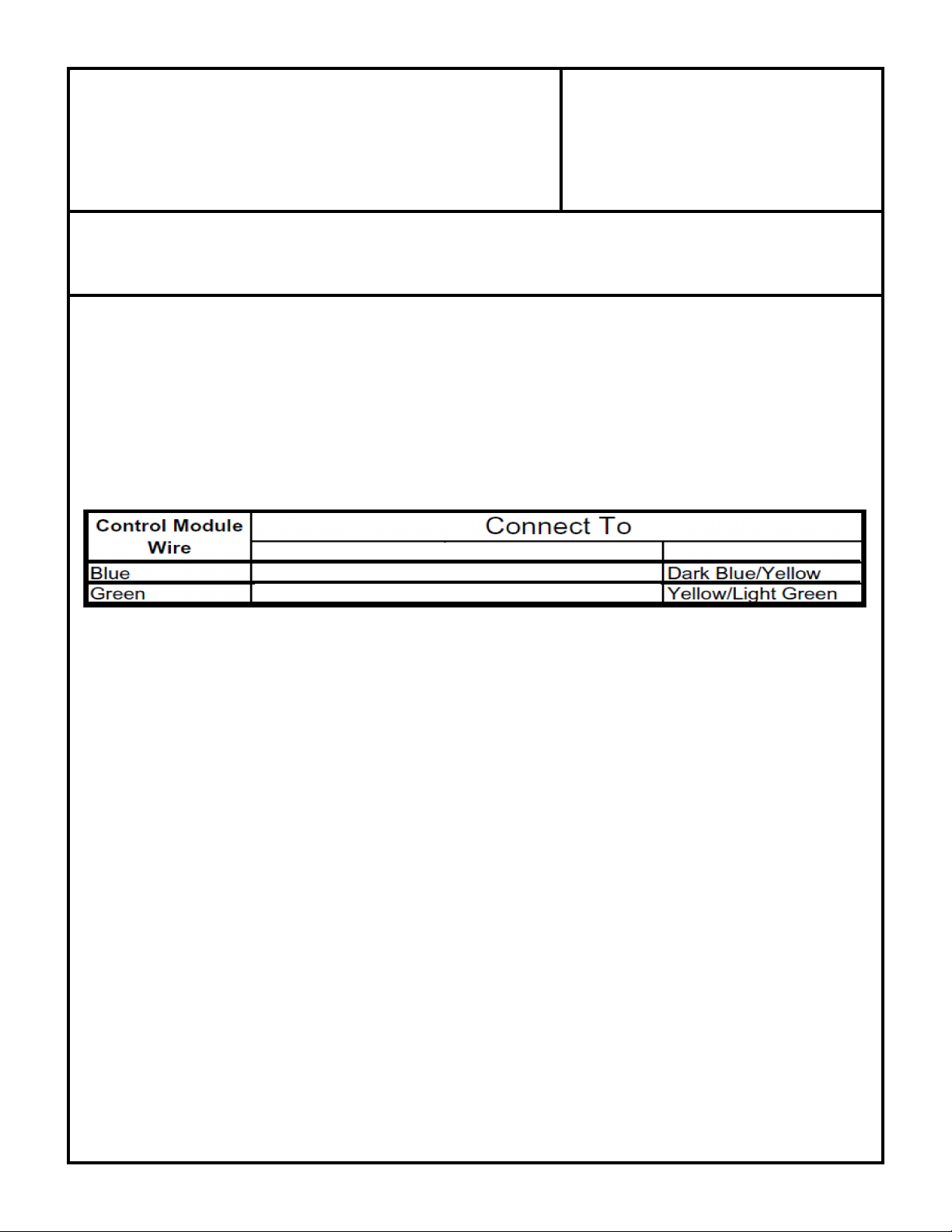
4. Solder the two wire Delphi connector to the vehicle wiring harness. See the chart below for vehicle specific
wiring.
07-12 JK
5. Heat shrink the soldered connections made in the previous step.
Installation:
1. Run the red (power) and black (ground) wires along the frame on the passenger side up to the fuse box.
Make sure to safely zip-tie the wiring away from the exhaust, any pinch points or other hot objects. The Fuse
attaches in the fuse box in the empty fuse slot labeled M14 - TTOW BUX on Jeeps up to 2011 and on
2012 JK's use slot M9. Refer to the under side of the fuse box lid for the proper location. (see photo's on
page 3 and 4)
A notch will need to be cut into the fuse box for the wire to run out, which can also be seen in Figure 3. The
ground can be run along the side of the fuse block to the ground terminal on the passenger fender next to the
fuse box.
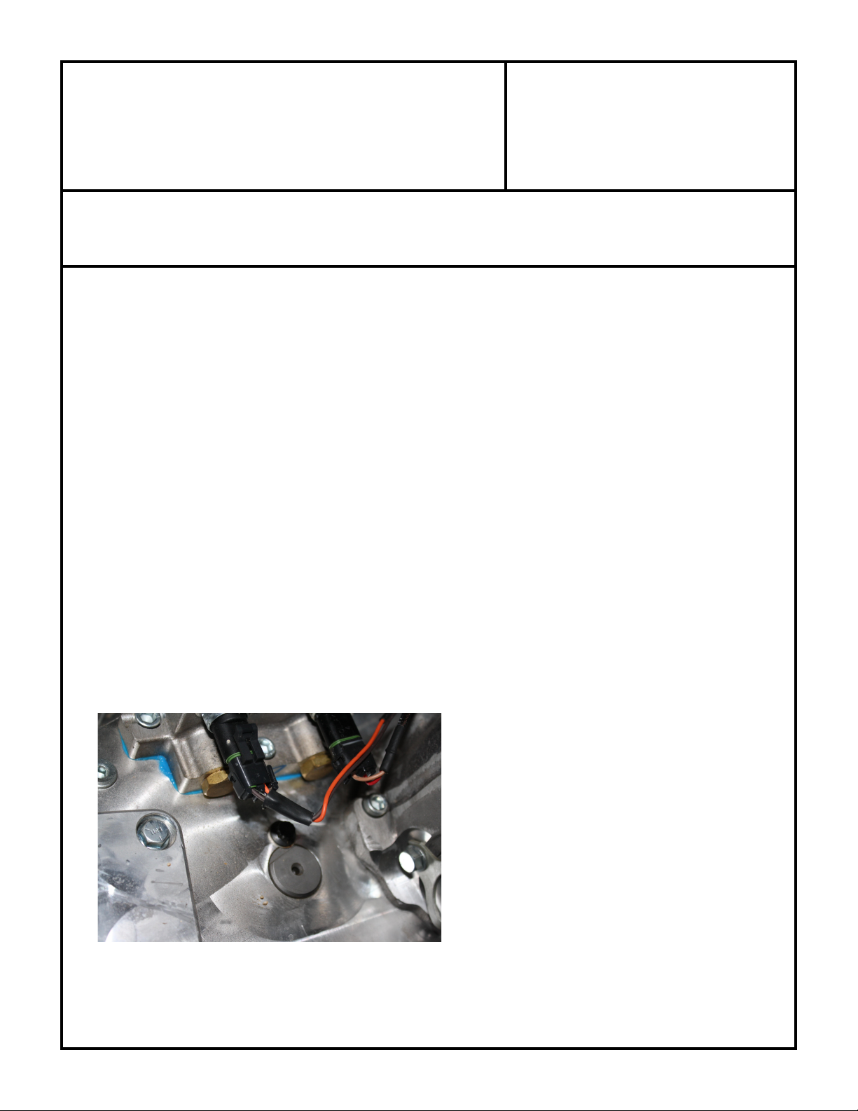
2. Install the low range switches into the Atlas shifter block. The switches do not use the white washer that was
installed with the plug bolt and when installing use a bit of RTV silicone on the threads.
SPECIAL NOTE: The components packaged in this kit have been assembled and machined for specific type of conversions. Modifications to any of the components
will void any possible warranty or return privileges. If you do not fully understand modifications or changes that will be required to complete your conversion, we
strongly recommend that you contact our sales department for more information. This instruction sheet is only to be used for the assembly of Advance Adapter
components. We recommend that a service manual pertaining to your vehicle be obtained for specific torque values, wiring diagrams and other related equipment.
These manuals are normally available at automotive dealerships and parts stores.
Page 3

ADVANCE ADAPTERS INC. P/N: 300377
P.O. Box 247, 4320 Aerotech Center Way New Item: (9/09)
Paso Robles, CA 93447 PAGE 3 OF 4
Telephone: (800) 350-2223 Fax: (805) 238-4201 Page Rev . Date: 11-07-14
JK A TLAS CONTROL MODULE
for NEW POLLAK SWITCHES
Fuse Splitter Installed
Notch
Figure 3: JK Power Connection
2007-2011
Jeep JK
Figure 4: JK Ground Terminal
The shifter block on the
Atlas in this photo was
redesigned in 2012 and the
switches now screw into
the bottom of the shifter
block, earlier versions of
the Atlas used the switches
coming from the sides of
the shifter block. The
installation of this kit
remains the same.
THE SWITCH CLOSEST TO THE
FRAME IS THE 4WD SWITCH
3. Plug 12" low range pigtail into the low range switch on transfer case .Connect the Pigtail to the control
module that has the (red and Tan) wires.
4. Plug 12" 4WD pigtail on to the front output side of the shifter block. This connects to the (orange and
brown) wires on the control module.
5. Plug the 3 wire Delphi plug into the power supply you ran earlier. Note the purple wire will not be used.
SPECIAL NOTE: The components packaged in this kit have been assembled and machined for specific type of conversions. Modifications to any of the components
will void any possible warranty or return privileges. If you do not fully understand modifications or changes that will be required to complete your conversion, we
strongly recommend that you contact our sales department for more information. This instruction sheet is only to be used for the assembly of Advance Adapter
components. We recommend that a service manual pertaining to your vehicle be obtained for specific torque values, wiring diagrams and other related equipment.
These manuals are normally available at automotive dealerships and parts stores.
THE SWITCH CLOSEST TO
THE REAR OUTPUT IS THE
LOW RANGE SWITCH
Page 4

ADVANCE ADAPTERS INC. P/N: 300377
P.O. Box 247, 4320 Aerotech Center Way New Item: (9/09)
Paso Robles, CA 93447 PAGE 4 OF 4
Telephone: (800) 350-2223 Fax: (805) 238-4201 Page Rev . Date: 11-07-14
JK A TLAS CONTROL MODULE
for NEW POLLAK SWITCHES
2012 Jeep JK's use
power from fuse slot M9.
Fuse box must be notched for the
wire to be routed out of the fuse box.
2012 Jeep JK's should be grounded at the battery.
SPECIAL NOTE: The components packaged in this kit have been assembled and machined for specific type of conversions. Modifications to any of the components
will void any possible warranty or return privileges. If you do not fully understand modifications or changes that will be required to complete your conversion, we
strongly recommend that you contact our sales department for more information. This instruction sheet is only to be used for the assembly of Advance Adapter
components. We recommend that a service manual pertaining to your vehicle be obtained for specific torque values, wiring diagrams and other related equipment.
These manuals are normally available at automotive dealerships and parts stores.
 Loading...