

Page 1
ADVANCE ADAPTERS INC. P/N: 15-1000
P.O. Box 247, 4320 Aerotech Center Way New Item: (7-09)
Paso Robles, CA 93447 PAGE 1 OF 4
Telephone: (800) 350-2223 Fax: (805) 238-4201 Page Rev . Date: 11-10-09
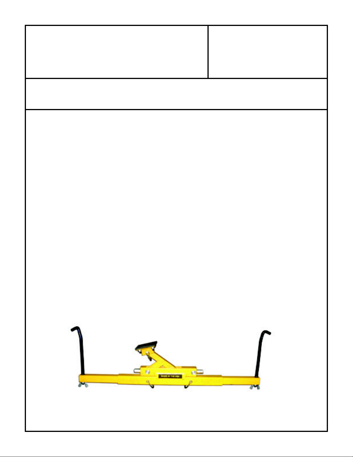
FRAME RAIL SUPPORTED
DRIVETRAIN JACK
KIT CONSISTS OF:
No. Qty. Part No. Description
1. 2 15-2005 "J" HANGER FRAME BOLT
2. 1 15-2007 MANUAL TRANSMISSION SADDLE (JEEP TRANSMISSIONS)
3. 1 15-2008 UNIVERSAL TRANSMISSION SUPPORT
4. 2 15-2012 TELESCOPING FRAME SUPPORTS
5. 1 15-2013 CENTER FRAME SUPPORT
6. 2 15-2022 UNIVERSAL FRAME HANGER BOLTS
7. 2 15-3002 1/2" WASHER
8. 2 15-3012 1/2" WING NUT
9. 3 15-3023 1/4" LOCKING PINS
10. 1 15-2001 CARRIER (JACK HOUSING)
THE FOLLOWING COMPONETS ARE INSTALLED INTO THE CARRIER (JACK ASSEMBLY):
11. 2 15-2009 SHORT ARM LIFTING SUPPORT (INSTALLED)
12. 1 15-2010 LONG ARM LIFTING SUPPORT (INSTALLED)
13. 1 15-2011 1/4" RIVET SHAFT (INSTALLED)
14. 1 15-2015 SLIDER PIN ALLTHREAD SUPPORT (INSTALLED)
15. 1 15-2016 SLIDER PIN ALLTHREAD SUPPORT W/ FLAT (INSTALLED)
16. 1 15-2017 THREADED CENTER PIN (INSTALLED)
17. 2 15-2020 LOAD WASHERS (INSTALLED)
18. 3 15-3002 1/2" WASHER (INSTALLED)
19. 1 15-3003 1/2" NYLON WASHER (INSTALLED)
20. 2 15-3006 5/8" COUPLING NUT (INSTALLED)
21. 1 15-3014 1/2-13 ADJUSTING SCREW (INSTALLED)
22. 4 15-3019 3/4" E-CLIP (INSTALLED)
23. 1 725004 1/2"-13 NUT (INSTALLED)
Patent Pending
SPECIAL NOTE: The components packaged in this kit have been assembled and machined for specific type of conversions. Modifications to any of the components will
void any possible warranty or return privileges. If you do not fully understand modifications or changes that will be required to complete your conversion, we strongly recommend
that you contact our sales department for more information. This instruction sheet is only to be used for the assembly of Advance Adapter components. We recommend that a
service manual pertaining to your vehicle be obtained for specific torque values, wiring diagrams and other related equipment. These manuals are normally available at automotive
dealerships and parts stores.
Page 2
ADVANCE ADAPTERS INC. P/N: 15-1000
P.O. Box 247, 4320 Aerotech Center Way New Item: (7/09)
Paso Robles, CA 93447 PAGE 2 OF 4
Telephone: (800) 350-2223 Fax: (805) 238-4201 Page Rev . Date: 07-06-09
FRAME RAIL SUPPORTED
DRIVETRAIN JACK
INSTALLATION NOTES:
The Uni-Raise is a frame rail supported drivetrain support system for trail repairs and drivetrain installations. The UniRaise comes with two types of frame rail support options. The first is the "J" hanger. Most frame rails have a certain
amount of factory holes in the frame rails. The "J" hanger can be used in most of these frame holes. The second support
method is the universal hanger. If the jack needs to be placed in a location where no holes are in the frame, the universal
hanger loops over the frame rail. The universal hanger is usually a bit harder to install because of the fuel and brake
lines that may interfere on the frame rail. Vehicles without a body lift may also be a tight fit when installing the universal
hangers. All hangers must be installed either on the inside or outside of the frame rails and must be clear of brake lines
and fuel line and any other equipment that may be fastened to the frame rails. The hangers must have a good contact
to the frame as they will be supporting the weight of the drivetrain.
Once each hanger per side is installed to the frame rail, the hangers should be pointing towards the ground. The center
support and telescoping frame supports will need to be slid together and adjusted to the width of the hanger bolts on
the frame. Install the 1/4" locking pins to the center support to lock the telescoping frame support into position. Install
the support section onto the frame hangers fastening them to the hangers with a 1/2" flat washer and then the 1/2" wing
nut. The wing nut should be installed with at least 1" of thread through the nut.
SPECIAL NOTE: The components packaged in this kit have been assembled and machined for specific type of conversions. Modifications to any of the components will
void any possible warranty or return privileges. If you do not fully understand modifications or changes that will be required to complete your conversion, we strongly recommend
that you contact our sales department for more information. This instruction sheet is only to be used for the assembly of Advance Adapter components. We recommend that a
service manual pertaining to your vehicle be obtained for specific torque values, wiring diagrams and other related equipment. These manuals are normally available at automotive
dealerships and parts stores.
Page 3

ADVANCE ADAPTERS INC. P/N: 15-1000
P.O. Box 247, 4320 Aerotech Center Way New Item: (7/09)
Paso Robles, CA 93447 PAGE 3 OF 4
Telephone: (800) 350-2223 Fax: (805) 238-4201 Page Rev . Date: 07-06-09
FRAME RAIL SUPPORTED
DRIVETRAIN JACK
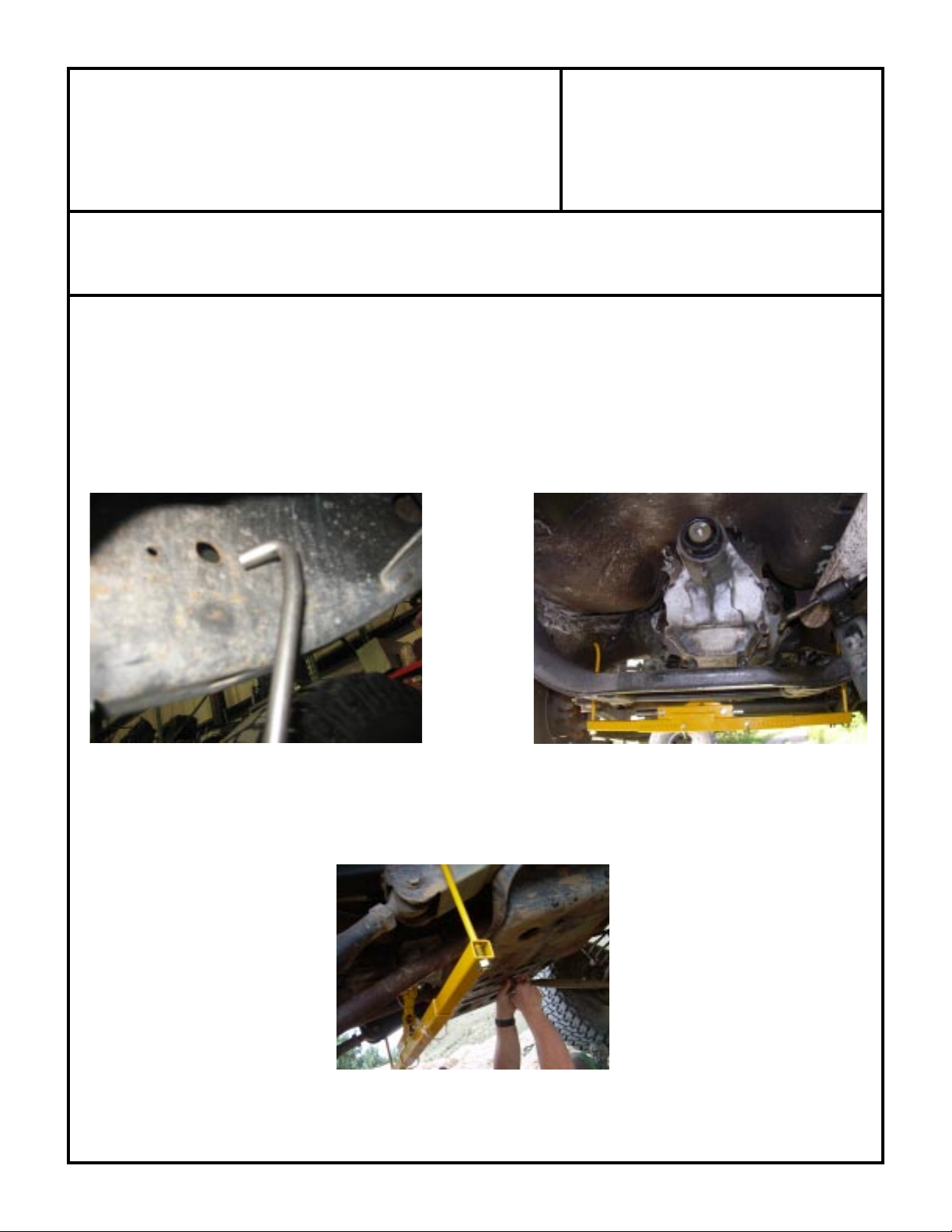
Use the transmission jack support that best fits your transmission and install it to the jack assembly using the 1/4" locking
pin. Attach the jack assembly to the Uni-Raise support that is installed on your vehicle. The jack can slide right or left
on the support to be centered under the drivetrain. The wing nuts on the hanger bolts can be adjusted higher up the
hangers to get the jack closer to the transmission if needed.
Using a 5/8" wench or socket, adjust the jack up so that it comes in contact with the transmission. Double check the
jack's alignment to the drivetrain, making sure it is centered. Put a little tension on the jack upward to the drivetrain
and wiggle the entire assembly to make sure it is secure. If all is good and secure, you can now proceed to remove
the drivetrain crossmember. The Uni-Raise can be used to raise or lower the drivetrain as needed.
SPECIAL NOTE: The components packaged in this kit have been assembled and machined for specific type of conversions. Modifications to any of the components will
void any possible warranty or return privileges. If you do not fully understand modifications or changes that will be required to complete your conversion, we strongly recommend
that you contact our sales department for more information. This instruction sheet is only to be used for the assembly of Advance Adapter components. We recommend that a
service manual pertaining to your vehicle be obtained for specific torque values, wiring diagrams and other related equipment. These manuals are normally available at automotive
dealerships and parts stores.
Page 4

ADVANCE ADAPTERS INC. P/N: 15-1000
P.O. Box 247, 4320 Aerotech Center Way New Item: (7/09)
Paso Robles, CA 93447 PAGE 4 OF 4
Telephone: (800) 350-2223 Fax: (805) 238-4201 Page Rev . Date: 07-06-09
FRAME RAIL SUPPORTED
DRIVETRAIN JACK
WARNINGS:
The Uni-raise is not a replacement for your stock crossmember. You can move a vehicle around by pushing
the vehicle while the Uni-Raise is installed, but the drivetrain should not be engaged under power.
While working under the vehicle with a Uni-Raise installed, use caution not to hit the jack system as it could
become disengaged from the drivetrain allowing the drivetrain to fall.
The Uni-Raise should not be used as an assembly that you can pry against as this can cause the jack
assembly to be disengaged from the drivetrain allowing the drivetrain to fall.
universal hanger
"J" hanger
transmission
supports
wing nuts
locking pins
jack assembly
jack support
SPECIAL NOTE: The components packaged in this kit have been assembled and machined for specific type of conversions. Modifications to any of the components will
void any possible warranty or return privileges. If you do not fully understand modifications or changes that will be required to complete your conversion, we strongly recommend
that you contact our sales department for more information. This instruction sheet is only to be used for the assembly of Advance Adapter components. We recommend that a
service manual pertaining to your vehicle be obtained for specific torque values, wiring diagrams and other related equipment. These manuals are normally available at automotive
dealerships and parts stores.
 Loading...