

Advance acoustic Convertamatic 28C, Convertamatic 26D, Convertamatic 24C, Convertamatic 26C, Convertamatic 28D Service Manual
Convertamatic™ 24D, 26D, 28D
™
Convertamatic
24C, 26C, 28C
Service Manual
Advance Models 56315000(24D-C), 56315001(26D), 56315002(28D),
56315003(24C-C), 56315004(28D-C), 56315005(28C-C),
56315006(X24D-C), 56315007(X24C-C), 56315008(26D-C),
56315009(X26D-C), 56315010(26C-C), 56315011(X26C-C),
56315012(X28D-C), 56315013(X28C-C)
2/05 revised 8/06 FORM NO. 56043098


TABLE OF CONTENTS
INTRODUCTION .......................................................................................................................................................................................... 2
CAUTIONS AND WARNINGS ...................................................................................................................................................................... 3
SPECIFICATIONS & MAINTENANCE ......................................................................................................................................................4-6
PM CHECKLIST ........................................................................................................................................................................................... 7
KNOW YOUR MACHINE ......................................................................................................................................................................... 8-12
SOLUTION SYSTEM .............................................................................................................................................................................13-19
FUNCTIONAL OVERVIEW ....................................................................................................................................................................... 13
CIRCUIT OVERVIEW SOLUTION AUTO MODE ..................................................................................................................................... 14
SOLUTION SYSTEM MAINTENANCE .................................................................................................................................................... 15
TROUBLESHOOTING GUIDE ............................................................................................................................................................16-17
SOLUTION SOLENOID VALVE REMOVAL .............................................................................................................................................. 18
SOLUTION VALVE DISASSEMBLY AND CLEANING .............................................................................................................................18
SOLUTION FILTER AND BALL VALVE REMOVAL .................................................................................................................................. 19
SOLUTION PUMP REMOVAL .................................................................................................................................................................. 19
SCRUB SYSTEM .................................................................................................................................................................................. 20-25
GENERAL BRUSH SYSTEM FUNCTIONAL OVERVIEW ....................................................................................................................... 20
SPECIAL SCRUB SYSTEM FUNCTIONS ..........................................................................................................................................20-21
SCRUB BRUSH DECK REMOVAL (DISC) .............................................................................................................................................. 22
SCRUB BRUSH LIFT ACTUATOR REMOVAL (DISC) ............................................................................................................................. 22
SCRUB BRUSH MOTOR/GEARBOX REMOVAL (DISC) ........................................................................................................................ 23
SCRUB BRUSH DECK REMOVAL (CYLINDRICAL) .......................................................................................................................... 24-25
SCRUB BRUSH MOTOR(S) REMOVAL (CYLINDRICAL) ..................................................................................................................24-25
SCRUB BRUSH BELT REPLACEMENT (CYLINDRICAL) ..................................................................................................................24-25
SCRUB BRUSH SYSTEM MAINTENANCE (CYLINDRICAL) ................................................................................................................. 24
SCRUB BRUSH REMOVAL AND INSTALLATION (CYLINDRICAL) ........................................................................................................ 24
SCRUB BRUSH LIFT ACTUATOR REMOVAL (CYLINDRICAL) ......................................................................................................... 24-25
RECOVERY SYSTEM ........................................................................................................................................................................... 26-32
FUNCTIONAL OVERVIEW ....................................................................................................................................................................... 26
VACUUM MOTOR CONTROL CIRCUIT OVERVIEW (AUTO MODE) ..................................................................................................... 27
VACUUM/RECOVERY SYSTEM MAINTENANCE CHECKLIST ............................................................................................................. 28
MAINTENANCE OF RECOVERY TANK FLOAT SWITCHES .................................................................................................................. 29
MAINTENANCE OF VACUUM MOTOR INLET SCREEN ........................................................................................................................30
VACUUM MOTOR REMOVAL .................................................................................................................................................................. 31
RECOVERY TANK REMOVAL ................................................................................................................................................................. 32
SQUEEGEE SYSTEM ........................................................................................................................................................................... 33-36
SQUEEGEE LIFT LINKAGE ADJUSTMENT ............................................................................................................................................ 33
SERVICING THE SQUEEGEE ................................................................................................................................................................. 34
ADJUSTING THE SQUEEGEE ................................................................................................................................................................ 34
SQUEEGEE MOUNT ASSEMBLY REMOVAL ......................................................................................................................................... 35
CASTER WHEEL REMOVAL ................................................................................................................................................................... 36
WHEEL DRIVE SYSTEM ......................................................................................................................................................................37-45
GENERAL FUNCTIONAL OVERVIEW ................................................................................................................................................37-39
WHEEL DRIVE TROUBLESHOOTING GUIDE ........................................................................................................................................ 40
DRIVE MOTOR TRANSAXLE REMOVAL ........................................................................................................................................... 41-42
DRIVE WHEEL REMOVAL ....................................................................................................................................................................... 43
(5K) POTENTIOMETER (R1) TESTING AND REMOVAL ........................................................................................................................ 44
(5K) POTENTIOMETER (R1) INSTALLATION AND ADJUSTMENT ................................................................................................... 44-45
(100K) POTENTIOMETER (R2) TESTING AND REMOVAL .................................................................................................................... 45
ELECTRICAL SYSTEM ......................................................................................................................................................................... 46-73
BATTERIES .............................................................................................................................................................................................. 46
DESCRIPTION OF THE LOW VOLTAGE CUTOUT FEATURE ...............................................................................
DESCRIPTION OF THE BATTERY CONDITION INDICATORS .............................................................................................................. 47
BATTERY CHARGING, MAINTENANCE AND TESTING ...................................................................................................................48-49
ACTUATOR DRIVE NUT ADJUSTMENT ............................................................................................................................................50-51
CURTIS CONTROLLER ...................................................................................................................................................................... 52-55
FUNCTIONAL OVERVIEW OF MAIN CONTROL BOARD ...................................................................................................................... 56
MAIN CONTROLLER ERROR CODES ................................................................................................................................................... 57
MAIN CONTROLLER DIAGNOSTIC SERVICE TEST MODE ............................................................................................................ 58-62
MAIN CONTROL PROGRAMING OPTIONS ...................................................................................................................................... 63-68
ELECTRICAL COMPONENT LOCATION ................................................................................................................................................ 69
WIRING DIAGRAM ................................................................................................................................................................................... 70
WIRING SCHEMATIC .............................................................................................................................................................................. 71
APPENDIX ............................................................................................................................................................................................. 72-74
DETERGENT (AXP) SYSTEM PLUMBING SCHEMATIC ........................................................................................................................ 72
EXTENDED SCRUB SYSTEM PLUMBING SCHEMATIC ....................................................................................................................... 73
DETERGENT (AXP) SYSTEM PREPARATION AND USE ......................................................................................................................74
Note: All references to right, left, front, or rear in this manual are as seen from the operator’s stand-point.
................................ 47
revised 8/05
FORM NO. 56043098 - Convertamatic™ 24C, 24D, 26C, 26D, 28C, 28D - 1

INTRODUCTION
This manual will help you get the most from your Convertamatic. Read it thoroughly before servicing the machine.
Note: Bold numbers and letters in parentheses indicate an item illustrated on pages 8-10.
PARTS AND SERVICE
Repairs, when required, should be performed by your Authorized Nilfi sk-Advance Service Center, who employs factory trained service personnel, and maintains an
inventory of Nilfi sk-Advance original replacement parts and accessories.
Call the NILFISK-ADVANCE DEALER named below for repair parts or service. Please specify the Model and Serial Number when discussing your machine.
(Dealer, affi x service sticker here.)
NAME PLATE
The Model Number and Serial Number of your machine are shown on the Nameplate on the machine. This information is needed when ordering repair parts for the
machine. Use the space below to note the Model Number and Serial Number of your machine for future reference.
MODEL NUMBER ______________________________________________
SERIAL NUMBER ______________________________________________
TRANSPORTING THE MACHINE
CAUTION!
Before transporting the machine on an open truck or trailer, make sure that . . .
• The machine is tied down securely.
• All access doors and covers are secured (tape and strap as needed).
TOWING
CAUTION!
If the machine must be towed or pushed, make sure the Master On/Off Key Switch (A) is in the OFF position and do not move the
machine faster than a normal walking pace (2-3 mph, 3-5kph) and for short distances only. Note: Disconnecting the wheel drive motor
wiring connector will make a disabled machine easier to push.
OTHER MANUALS AVAILABLE FOR YOUR MACHINE
The manuals listed below can be found via Nilfi sk-Advance’s two electronic supported databases. They are:
• Nilfi sk-Advance Dealer Customer Zone
• Ezparts service / parts CD-Rom
• 56041596 – Instructions for Use
• 56042451 – Parts List
2 - FORM NO. 56043098 - Convertamatic™ 24C, 24D, 26C, 26D, 28C, 28D
CAUTIONS AND WARNINGS
SYMBOLS
Nilfi sk-Advance uses the symbols below to signal potentially dangerous conditions. Read this information carefully and take the
necessary steps to protect personnel and property.
DANGER!
Is used to warn of immediate hazards that will cause severe personal injury or death.
WARNING!
Is used to call attention to a situation that could cause severe personal injury.
CAUTION!
Is used to call attention to a situation that could cause minor personal injury or damage to the machine or other property.
Read all instructions before using.
GENERAL SAFETY INSTRUCTIONS
Specifi c Cautions and Warnings are included to warn you of potential danger of machine damage or bodily harm.
WARNING!
* This machine should only be used by properly trained and authorized persons.
* While on ramps or inclines, avoid sudden stops when loaded. Avoid abrupt sharp turns. Use low speed down hills. Clean only while ascending (driving up)
the ramp.
* Keep sparks, fl ame and smoking materials away from batteries. Explosive gases are vented during normal operation.
* Charging the batteries produces highly explosive hydrogen gas. Charge batteries only in well-ventilated areas away from open fl ame. Do not smoke while
charging the batteries.
* Remove all jewelry when working near electrical components.
* Turn the key switch off (O) and disconnect the batteries before servicing electrical components.
* Never work under a machine without safety blocks or stands to support the machine.
* Do not dispense fl ammable cleaning agents, operate the machine on or near these agents, or operate in areas where fl ammable liquids exist.
* Do not clean this machine with a pressure washer.
* Do not operate this machine on ramps or inclines of more than a 2 percent gradient.
* Only use the brushes provided with the appliance or those specifi ed in the instruction manual. The use of other brushes may impair safety.
CAUTION!
* This machine is not approved for use on public paths or roads.
* This machine is not suitable for picking up hazardous dust.
* Use care when using scarifi er discs and grinding stones. Nilfi sk-Advance will not be held responsible for any damage to fl oor surfaces caused by scarifi ers or
grinding stones.
* When operating this machine, ensure that third parties, particularly children, are not endangered.
* Before performing any service function, carefully read all instructions pertaining to that function.
* Do not leave the machine unattended without fi rst turning the key switch off (O), removing the key and securing the machine.
* Turn the key switch off (O) and remove the key, before changing the brushes, and before opening any access panels.
* Take precautions to prevent hair, jewelry, or loose clothing from becoming caught in moving parts.
* Use caution when moving this machine in below freezing temperature conditions. Any water in the solution or recovery tanks or in the hose lines could freeze,
causing damage to valves and fi ttings. Flush with windshield washer fl uid.
* The batteries must be removed from the machine before the machine is scrapped. The disposal of the batteries should be safely done in accordance with your
local environmental regulations.
* Do not use on surfaces having a gradient exceeding that marked on the machine.
* All doors and covers are to be positioned as indicated in the instruction manual before using the machine.
* Refer to “Onboard Battery Charger” section at back of manual for additional specifi c battery charger warnings.
SAVE THESE INSTRUCTIONS
FORM NO. 56043098 - Convertamatic™ 24C, 24D, 26C, 26D, 28C, 28D - 3
TECHNICAL SPECIFICATIONS
28C
Convertamatic
26C
Convertamatic
/hr 32,050 ft²/hr 35,000 ft²/hr
24C
9,600 ft²
Convertamatic
28D
Convertamatic
26D
Convertamatic
brushes
(2) 27 in (69 cm)
brushes
(2) 25 in (64 cm)
brushes
(2) 23 in (58 cm)
holders
brushes or pad
(2) 14 in (35.5 cm)
holders
brushes or pad
(2) 13 in (33 cm)
W=31 in (79 cm)
L=55 in (140 cm)
H=44 in (112 cm)
in (74 cm)
W=29
L=55 in (140 cm)
H=44 in (112 cm)
W=27 in (69 cm)
L=55 in (140 cm)
H=44 in (112 cm)
W=30 in (76 cm)
L=55.5 in (141 cm)
H=44 in (112 cm)
W=27.5 in (70 cm)
L=55 in (140 cm)
H=44 in (112 cm)
24 Volt
(4) 6 volt batteries (wet acid and gel cell available)
24 volt, 25 amp Wet/Gel Compatible
Precision-Flow electric pump
20 gal. (76L)
20 gal. (76L)
(2) .50 hp (375 watt)
0.75 hp (560 watt) 3-stage
66 dB(A) at operator’s position
0.4 hp (300 watt) variable forward and reverse, max speed =3 mph (4.83 km/hr), 10% gradeability
(2) 7 in. (18cm) dia. foam-fi lled, gray non-marking
Convertamatic 24D
Disc Cylindrical
/hr 32,050 ft²/hr 35,000 ft²/hr 2
9,600 ft²
2
24 in (61cm) 26 in (66cm) 28 in (71cm) 24 in (61cm) 26 in (66cm) 28 in (71cm)
²/hr) (3,000 m²/hr) (3,200 m²/hr) (2,750m²/hr) (3,000 m²/hr) (3,200 m²/hr)
15,800 ft²/hr 17,200 ft²/hr 18,500 ft²/hr 15,800 ft²/hr 17,200 ft²/hr 18,500 ft²/hr
(2,750m
(1468 m²/hr) (1598 m²/hr) (1719 m²/hr) (1598 m²/hr) (1598 m²/hr) (1719 m²/hr)
(2) 12 in (30.5 cm) brushes or pad holders
Regular Scrub
max 80 lbs max 60 lbs
max 130 lbs max 80 lbs
max 160 lbs max 100 lbs
Heavy Scrub
Extreme Scrub
.25 gal/min (.95 L/min) or 80 minutes per solution tank
220 rpm 900 rpm
32.6 in (83 cm) 36.6 in (93 cm) 36.6 in (93 cm) 32.6 in (83 cm) 36.6 in (93 cm) 36.6 in (93 cm)
W=26 in (66 cm) L=54.5 in (138 cm) H=44 in (112 cm)
780 lb (354 kg) 780 lb (354 kg) 780 lb (354 kg) 780 lb (354 kg) 780 lb (354 kg) 780 lb (354 kg)
Regular Scrub
Heavy Scrub .50 gal/min (1.9 L/min) or 40 minutes per solution tank
Extreme Scrub .75 gal/min (2.8 L/min) or 27 minutes per solution tank
uum Motor
Voltage
Power Source
Onboard Battery Charger
Solution Control
Solution Tank
Recovery Tank
Scrub Motors
Vac
Sound Level
Drive System
Drive Wheels
Scrub Head Type
Scrub Path
Max Productivity @ 2.8 mph
Max Productivity @ 1.5mph
4 - FORM NO. 56043098 - Convertamatic™ 24C, 24D, 26C, 26D, 28C, 28D
Scrub Head Size & Type
Scrub
Pressure
Scrub Head Speed
Solution
Flow Rate
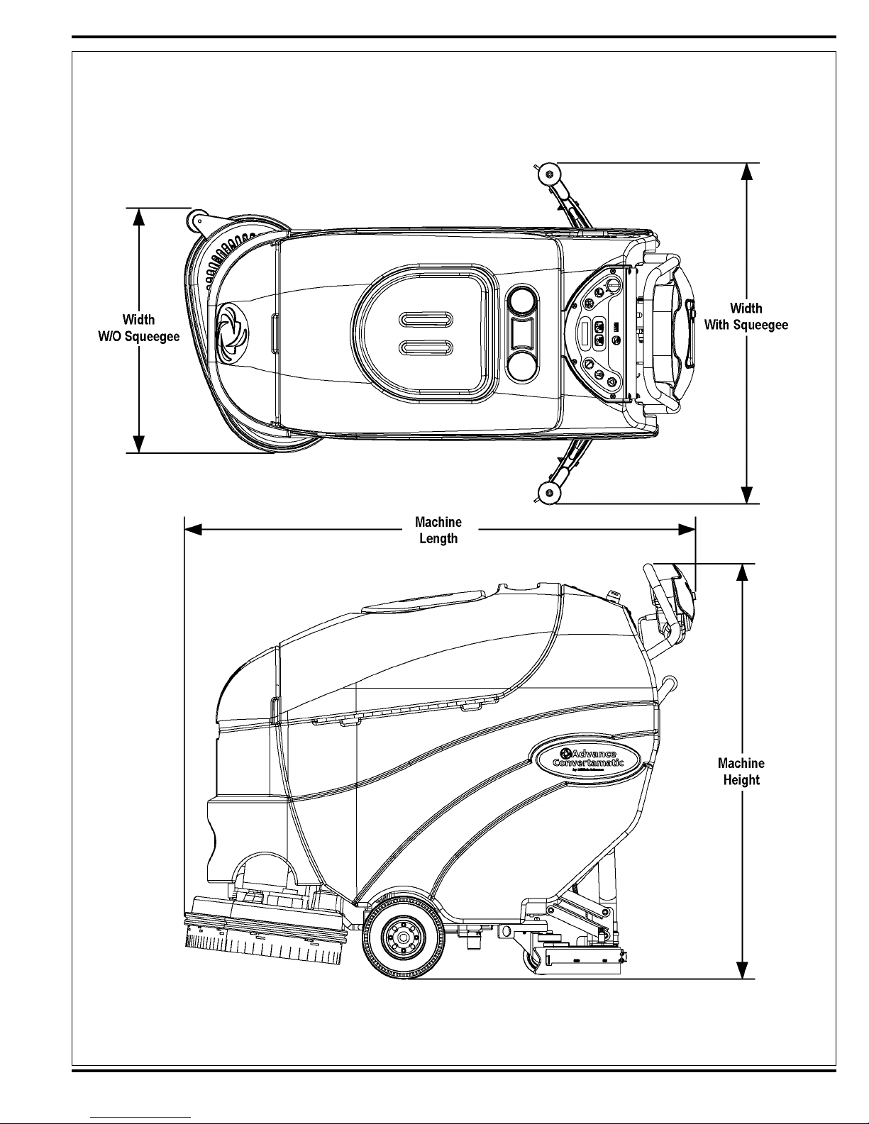
Squeegee Width
Dimensions (w/o squeegee)
Weight w/ Batteries
Smart Solutions AXP
Refi llable Cartridge Capacity 1.25 gal (4.75 L)
Available Dilution Rates 32:1, 50:1, 64:1, 100:1, 128:1, 150:1, 200:1, 256:1, & 300:1
Low Detergent Warning Standard
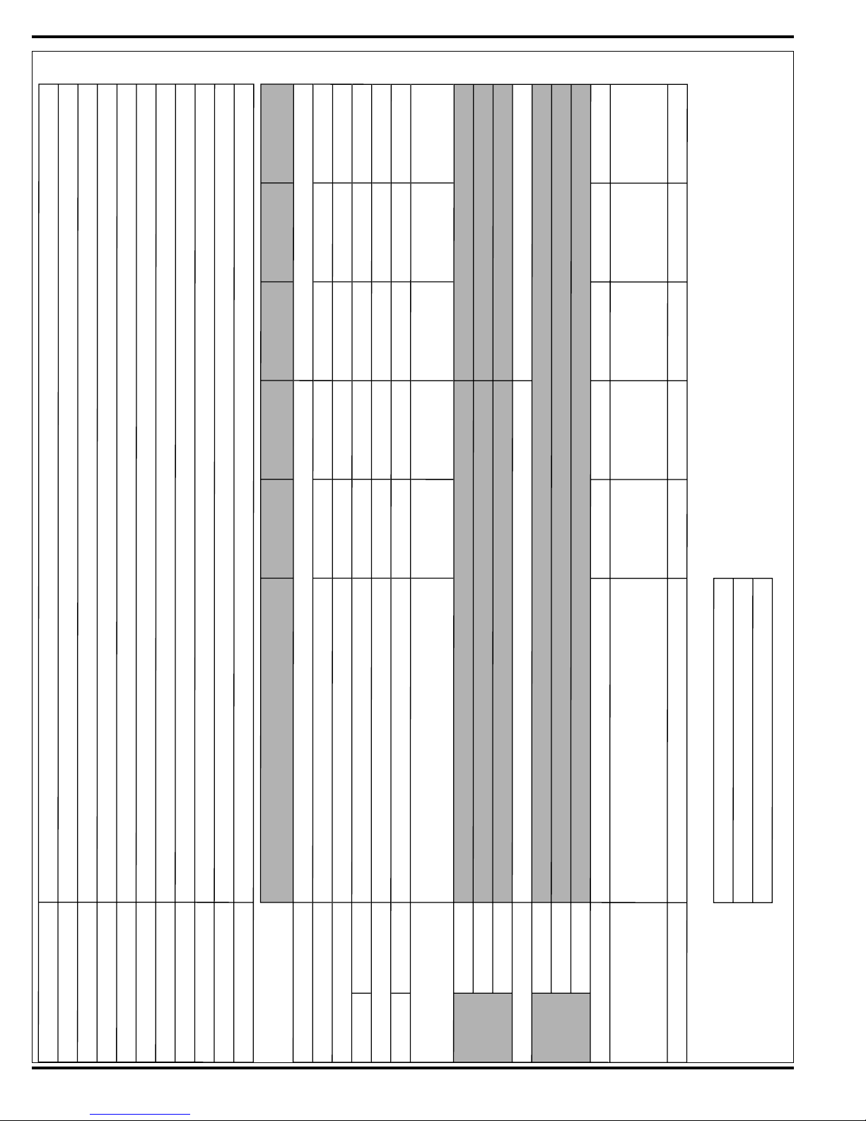
SPECIFICATIONS
FORM NO. 56043098 - Convertamatic™ 24C, 24D, 26C, 26D, 28C, 28D - 5
MAINTENANCE SCHEDULE
Maintenance intervals given are for average operating conditions. Machines used in severe operational environments may require service more often.
MAINTENANCE ITEM Daily Weekly Monthly Yearly
Charge Batteries X
Check/Clean Tanks & Hoses (clean recovery tank switches & vacuum inlet screen) X
Check/Clean/Rotate the Brushes/Pads X
Check/Clean the Squeegee X
Clean Hopper on Cylindrical System X
Purge Extended Scrub System (if installed) X
Check Each Battery Cell(s) Water Level (does not apply to gel cell batteries) X
Inspect Scrub Housing Skirts X
Inspect and clean Solution Filter X
Clean Solution Trough on Cylindrical System X
Lubricate the Machine X
* Check Carbon Brushes X
Note: See the individual machine system sections for maintenance information.
* Have Nilfi sk-Advance check the vacuum motor carbon motor brushes once a year or after 300 operating hours. The brush and drive motor carbon brushes check
every 500 hours or once a year.
WARNING!
Turn the key switch off and disconnect the batteries before servicing the machine.
* Check vacuum motor carbon brushes (Qty 2) once a year or after 300 operating hours.
* Check brush and wheel drive motor(s) carbon brushes (Qty 4 per motor) once a year or after 500 operating hours.
* The original (new) length of each carbon brush is 1” (25.4mm) on all 24 volt machine models brush and wheel drive motors.
* All motors: Replace carbon brushes when shorter than 3/8” (9.5mm) to obtain the same motor effi ciency as new brushes.
IMPORTANT!
Motor damage resulting from failure to service the carbon brushes is not covered under warranty. See the Limited Warranty
Statement.
BATTERIES AND CHARGERS
Attention: See the ELECTRICAL SYSTEM section for battery installation, battery maintenance and charger system requirements.
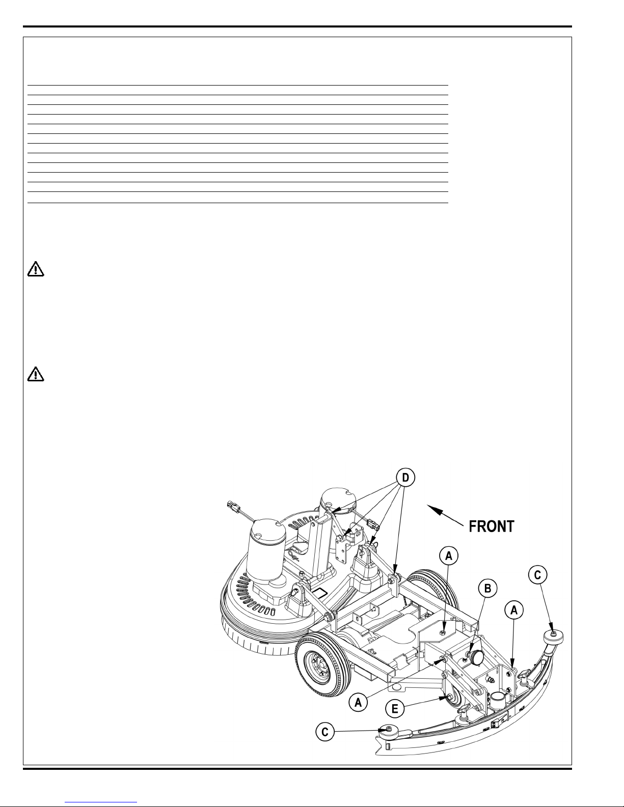
LUBRICATING THE MACHINE
Once a month, apply light machine oil to lubricate the:
• General Pivot Points for the Squeegee Linkage (A).
• Squeegee mount angle adjustment knob threads (B).
• Squeegee Tool end wheels (C).
• General Pivot Points for the Brush Linkage (D).
• Scrub Deck Bumper Wheels.
Once per quarter, Grease the following
• Rear Caster Wheel Swivel (E).
6 - FORM NO. 56043098 - Convertamatic™ 24C, 24D, 26C, 26D, 28C, 28D
revised 8/05

Advance Convertamatic™ 24/26/28 C/D Models
Cylindrical and Disc
PM Checklist
Defect Codes
Customer A needs adjustment
B binding
Address C dirty or contaminated
D damaged, bent or torn
City St Zip L leaks
M missing
Model Serial Hours W worn out
OPERATIONAL INSPECTION ITEMS
Ref
1 Drive Paddle Operation (check for Fwd/Rev Drive & any neutral creep) A B D
2 Drive System Performance (Speed Changes Min/Max) noisy sluggish
3 Scrub System (Raise/Lower, Brush Motor On/Off & Optional Brush Remove Feature)
4 Scrub Brush Pressure settings (1-3)
5 Squeegee System (Raise/Lower & Squeegee Tool pickup Performance) A B D
6 Vac Performance (Sealed water lift & 1” open hole adapter, 24v-56/9) C L W
7 Solution Control (On/Off Manual /Auto and Flow Volume settings 1,2 &3) A B L
8 Battery Charger (Auto turn ON & OFF) D
9 Main Controller Special Program Options (see SVR manual 56043098). Check all applicable
machine settings. Examples: Scrub mode pressure settings, SVR test mode, low voltage cutout
etc.
OK
Defect Codes
(circle)
A B D
A B
A
Does
Not
Work
VISUAL INSPECTION ITEMS
Ref
10 Scrub Brushes, check for wear and rotate
11 Scrub Brush Motor(s), check for carbon brush wear 500 Hours B C W
12 Scrub Brush Motor(s), check gearboxes (disc) B D L
13 Brush Drive Plate Retainer Clips & flex couplers (disc) C D M
14 Scrub Deck Lift Motor, Skirt & Side Wheel D M W
15 Solution Solenoid Valve C L W
16 Solution Pump & Hoses C L W
17 Solution Tank, Delivery Hoses & Filter clean filter screen C L
18 Vacuum Motor Carbon Brushes (wear limit 3/8”) 300 Hours B C W
19 Vacuum motor inlet filter (located in recovery tank) clean screen C D M
20 Recovery Tank Cover Gasket L M W
21 Recovery Tank Drain Hose & Cap
22 Squeegee Pick-Up Hose back flush C D L
23 Squeegee Tool & Blades (clean, rotate & adjust)
24 Squeegee Tool lift cable & mount Wheels (lubricate) two side & one floor A D W
25 Battery Condition (load test, clean & water) C W
26 Drive Wheel Trans Axle Motor Check Carbon Brushes 500 Hours B C D W
27 Trans Axle Drive Tires tread wear W
28 Rear chassis Caster Wheel (Lubricate) tread wear W
Comments OK
Defect Codes
(circle)
D M W
C D L
A D W
NOTE: For additional service information see service manual form number 56043098 and operator manual form
number 56041596.
WORK COMPLETED BY: ACKNOWLEDGED BY:
Does
Not
Work
Service Technician Signature Date Customer Signature Date
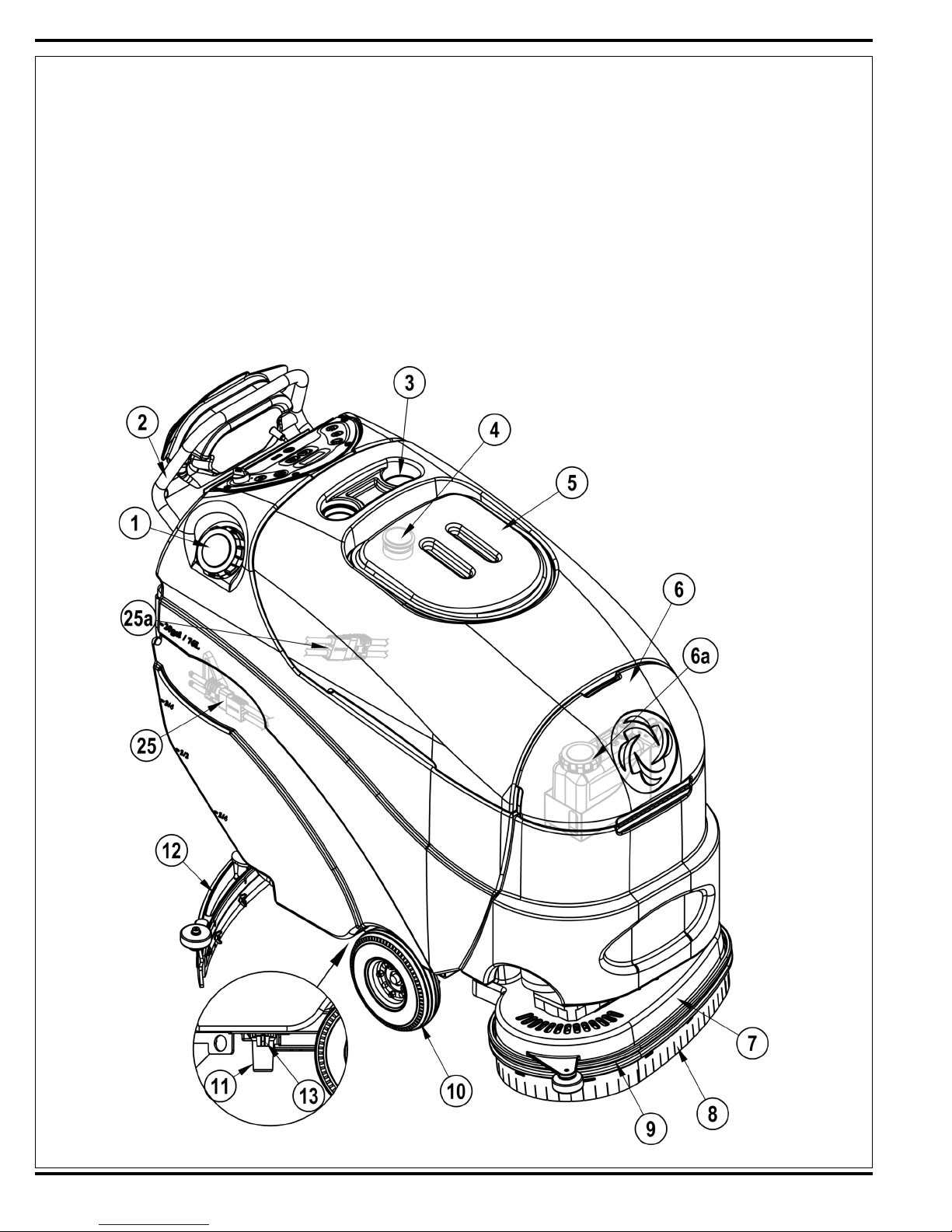
KNOW YOUR MACHINE
As you read this manual, you will occasionally run across a bold number or letter in parentheses - example: (2). These numbers refer to an item shown on this page
unless otherwise noted. Refer back to this page whenever necessary, to pinpoint the location of an item mentioned in the text. NOTE: Refer to the service manual
for detailed explanations of each item illustrated on the next 3 pages.
1 Solution Tank Fill
2 Operator Control Handle
3 Bottle Holders
4 Vacuum Motor Inlet Screen
5 Recovery Tank Cover
6 Detergent (AXP) Cartridge Access Cover
6a Detergent (AXP) Cartridge (AXP models only)
7 Scrub Deck
8 Scrub Deck Skirt
9 Scrub Deck Bumper
10 Drive Wheel
11 Solution Filter
12 Squeegee Assembly
13 Solution Shut-Off Valve
8 - FORM NO. 56043098 - Convertamatic™ 24C, 24D, 26C, 26D, 28C, 28D
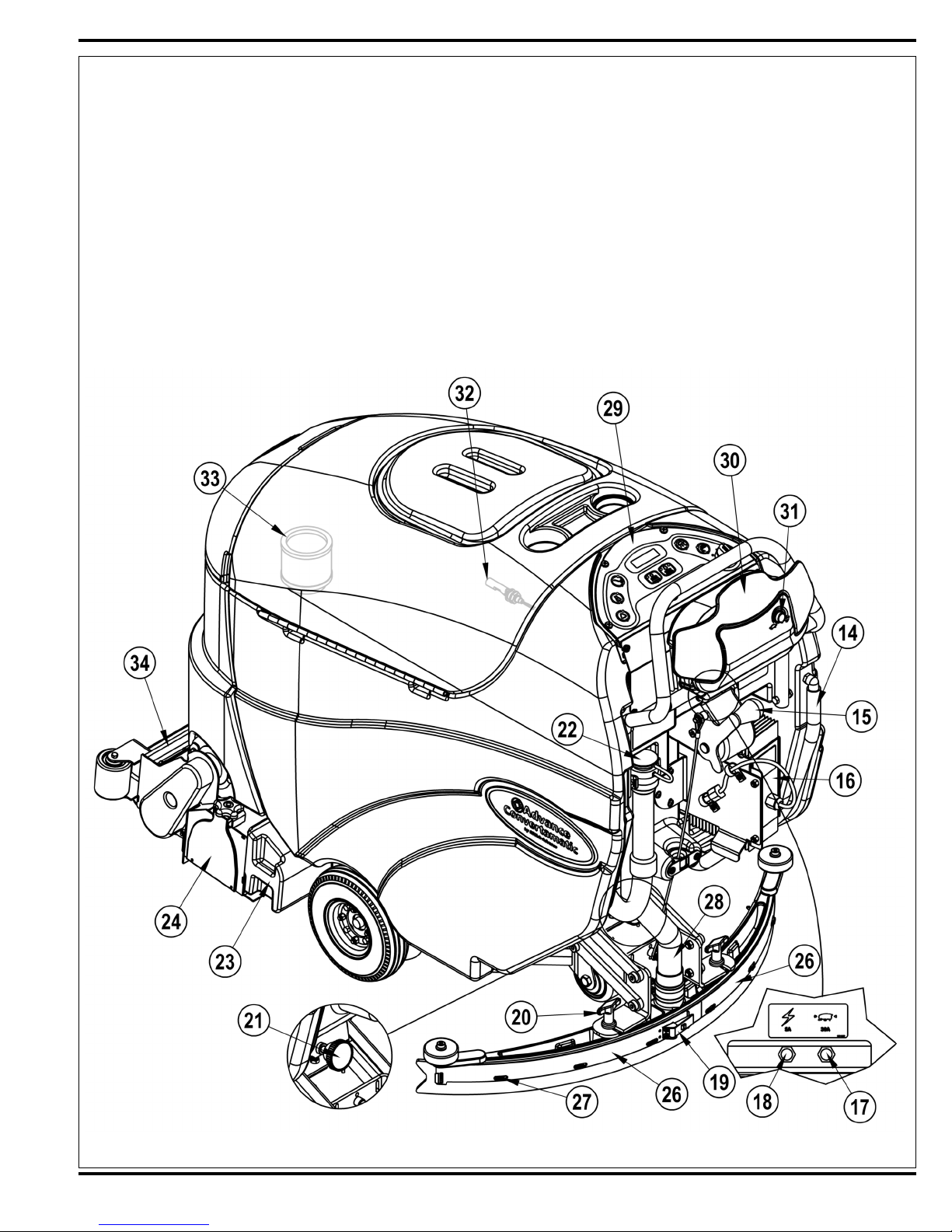
KNOW YOUR MACHINE
14 Solution Drain Hose / Level Indicator
15 Squeegee Raise / Lower Lever
16 Onboard Battery Charger (Not found on all models)
17 Wheel Drive Circuit Breaker
18 Control Circuit Circuit Breaker
19 Squeegee Blade Latch
20 Squeegee Mount Thumb Nut
21 Squeegee Adjustment Knob
22 Recovery Tank Drain Hose
23 Debris Hopper (Cylindrical Models Only)
24 Idler Assembly (Cylindrical Models Only)
25 Battery Pack Connector (non onboard charger models only)
25a Battery Pack Connector (onboard charger models only)
26 Squeegee Blade Tension Strap
27 Squeegee Blade Alignment Pins
28 Recovery Hose
29 Control Panel
30 Drive Paddle
31 Speed Limit Control Knob
32 Vacuum Shut Off Switch
33 Extended Scrub Filter (Optional)
34 Solution Manifold (Cylindrical Models Only)
FORM NO. 56043098 - Convertamatic™ 24C, 24D, 26C, 26D, 28C, 28D - 9
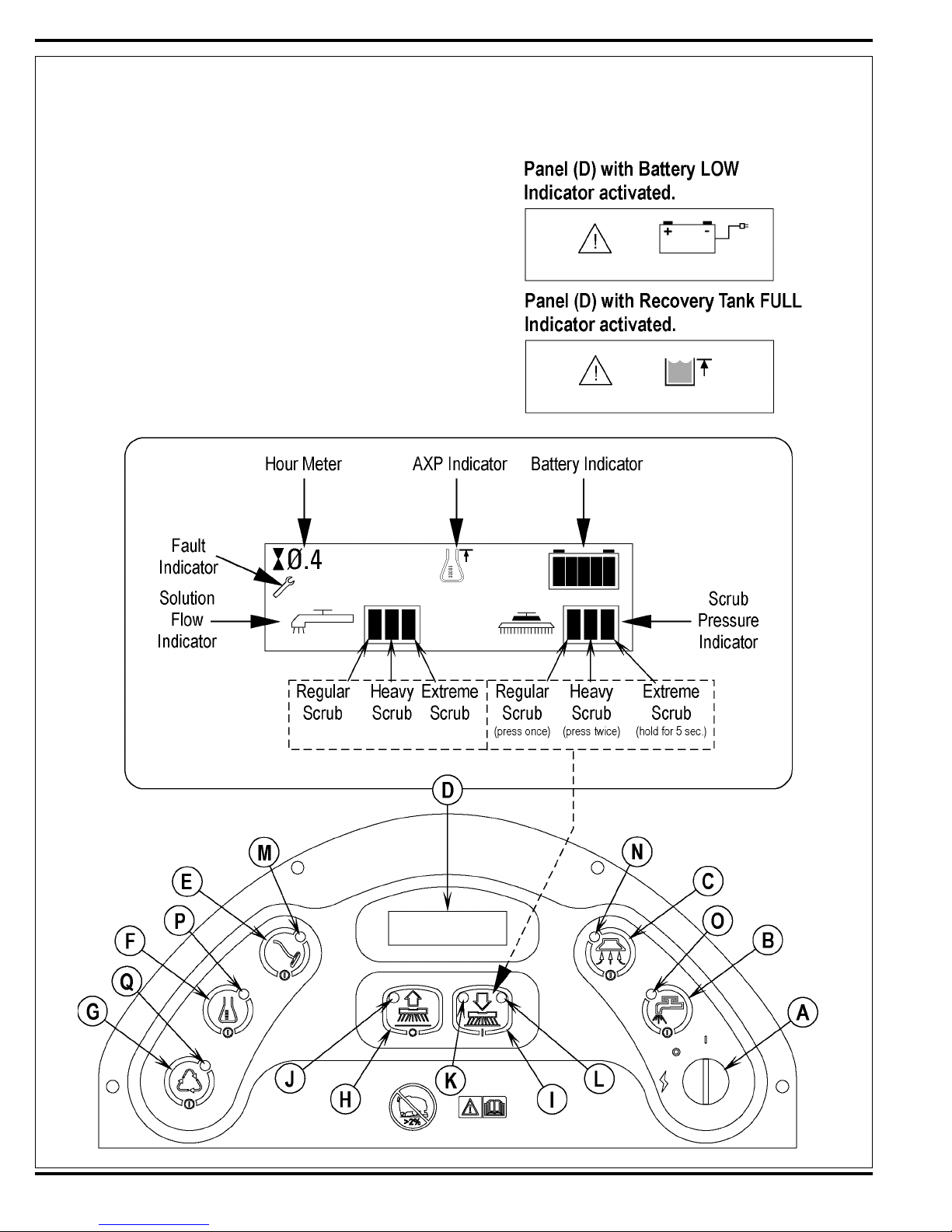
KNOW YOUR MACHINE
A Key Switch (Main Power)
B Solution Switch
C Vacuum Switch
D Display Panel
Solution Flow Indicator
AXP Indicator
Hour Meter
Battery Indicator
Scrub Pressure Indicator
Recovery Tank FULL Indicator
Fault Indicator
E Wand Switch (Dealer Installed Option)
F Detergent System (AXP models only)
G Extended Scrub System (Dealer Installed Option)
H Scrub OFF
I Scrub ON
10 - FORM NO. 56043098 - Convertamatic™ 24C, 24D, 26C, 26D, 28C, 28D

KNOW YOUR MACHINE
FUNCTIONAL DESCRIPTION OF CONTROL PANEL:
The controls on the Convertamatic were designed with one touch operation in mind. For single pass scrubbing the user can simply depress one
switch and all systems on the machine will be ready to go. For most single-pass scrubbing operations, the operator should only need to use the
middle switches on the control panel. These are the Scrub System OFF and Scrub system ON switches.
Scrub OFF Switch (H) - Pressing this switch when the unit is in a scrub mode will cause the following to occur:
• The scrub brushes will turn off and the scrub deck will be raised to the up position
• The solution fl ow will be stopped
• The fi rst time that this switch is pressed, the vacuum system will NOT be turned off. This is so that any remaining water may be picked up without
having to turn the vacuum back on. If this switch is pressed a second time (pressed after the scrub system has been turned off) the vacuum will shut
of after a 10 second delay.
Scrub ON Switch (I) – If the scrub system is off, pressing this switch once will cause the following to occur:
• The scrub system will be enabled with the scrub pressure set to the regular setting and the scrub deck will be lowered. Note press twice for the
heavy scrub pressure mode and hold this switch for 5 seconds to enter the extreme scrub mode.
• The vacuum system will be enabled.
• The solution system will be enabled.
• As soon as the throttle (operator drive paddle) is moved from the neutral position the scrub brushes will start turning and the vacuum will turn on. If
the direction is forward the solution fl ow will start. If the direction is reverse, the solution fl ow will be stopped. If the scrub system is already enabled
when this switch is pressed, the scrub pressure will increase to the heavy scrub mode. If the switch is held for 5 seconds the pressure will change
to the extreme scrub mode. At the same time the panel display will show the correct changed scrub pressure setting.
Wand Switch (E) – This switch is used when an external vacuum/scrub wand is used. Pressing this switch will turn the vacuum on continuously
without regard to the throttle position. If the scrub system was on it will be turned off. This includes turning off the scrub brushes and turning the
solution fl ow off (to the scrub deck). NOTE: automatic shutoff of the vacuum motor when the recovery tank is full is disabled when the wand is
enabled.
Key Switch (A) – Main power switch
Vacuum Switch (C) – This switch is used to turn the vacuum system on or off. Pressing this switch will alternate between on and off. The vacuum
will only turn on when the throttle is moved from the neutral position. It will remain on for 10 seconds after the throttle returns to neutral.
The vacuum also has an automatic shutoff feature that will turn the vacuum and scrub systems off if the recovery tank becomes full.
Solution Switch (B) - This switch is used to turn the solution system on or off. Pressing this switch when the scrub system has been activated will
alternate between on and off. The solution fl ow will only turn on when the throttle is moved from the neutral position in the forward direction. The
solution fl ow will turn off if the throttle returns to neutral or is moved to reverse. Pressing this switch when the scrub system is off will momentarily
turn the solution fl ow on to allow pre-wetting of the scrub brushes.
Chemical Switch (F) – Pressing this switch will turn on or off the chemical option. See the main programming options in this manual to select
(activate) the onboard chemical distribution system.
Extended Scrub (Recycle) Switch (G) - Pressing this switch will turn on or off the recycle option. See the main programming options in this manual
to select (activate) the recycle option.
FORM NO. 56043098 - Convertamatic™ 24C, 24D, 26C, 26D, 28C, 28D - 11

KNOW YOUR MACHINE
DESCRIPTION OF INDICATORS ON THE CONTROL PANEL:
In general, the following guidelines apply to the control panel indicators:
A fl ashing green or yellow indicator means that a fault has occurred in the particular system. An example of this would be an over-current fault.
A yellow indicator means that the particular function has been enabled but is not currently on. For example, if a scrub mode is selected and the
throttle is in neutral, the scrub system, vacuum, and solution indicators will all be yellow indicating that the systems are enabled and ready to turn
on when the throttle is moved to forward or reverse.
A green indicator means that the particular system is on.
A fl ashing green indicator means that the particular system is in a delayed-off condition. An example of this is when a scrub mode is selected and
the throttle goes from forward or reverse to neutral. When this happens the vacuum indicator will fl ash green indicating that the vacuum is still on but
that it will be turning off after the delay period.
Scrub OFF Indicator (J):
• This indicator will be green if the scrub system is off and ready to be activated.
• This indicator will be red if the scrub system has been turned off and the scrub deck is not up yet.
• This indicator will fl ash red if there is a fault in the scrub system.
• This indicator will be off if the scrub system has been activated.
Regular Scrub ON Indicator (K):
• This indicator will be yellow if the scrub system is enabled in “Regular” scrub mode but the drive paddle is in neutral.
• This indicator will be green if the scrub system has been turned on in “Regular” scrub mode and the machine is moving in either direction.
• This indicator will be off if the scrub system has been turned OFF.
Heavy Scrub ON Indicator (L):
• This indicator will be yellow if the scrub system is enabled in “Heavy” scrub mode but the drive paddle is in neutral.
• This indicator will be green if the scrub system has been turned on in “Heavy” scrub mode and the machine is moving in either direction.
• This indicator will be off if the scrub system has been turned OFF.
Extreme Scrub ON Indicators (K & L):
• Both of these indicators will be yellow if the scrub system is enabled in “Extreme” scrub mode but the drive paddle is in neutral.
• Both of these indicators will be green if the scrub system has been turned on in “Extreme” scrub mode and the machine is moving in either
direction.
Control panel LED Display (D):
See the detailed drawing shown in the Know Your Machine manual section for the specifi c description of the individual icon symbols. NOTE: If a
speed control fault occurs (error code 3) the wand indicator will fl ash the fault code produced by the Curtis speed control. Refer to the service manual
troubleshooting section for details.
Wand Switch Indicator (M):
• This indicator will be green if the Wand Switch has been turned ON.
• This indicator will be off if the Wand Switch has been turned OFF.
Vacuum System Indicator (N):
• This indicator will be green if the vacuum is on.
• This indicator will fl ash green if the vacuum is in the 10 second delayed-off condition.
• This indicator will be yellow if the vacuum is enabled but the drive pedal is in neutral.
• This indicator will fl ash yellow if there is a vacuum system fault.
• This indicator will be off if the vacuum is disabled and turned off.
Solution System Indicator (O):
• This indicator will be green if the solution is on.
• This indicator will be yellow if the solution is enabled but the drive paddle is in neutral.
• This indicator will fl ash yellow if there is a solution system fault.
• This indicator will be off if the solution is disabled and turned off.
Chemical “AXP” System Indicator (P):
• This indicator will be green if the AXP system is on.
• This indicator will be yellow if the AXP system is enabled but the drive paddle is in neutral.
• This indicator will be off if the AXP system is disabled and turned off.
Extended Scrub System Indicator (Q):
• This indicator will be green if the Extended Scrub system is on.
• This indicator will be yellow if the Extended Scrub system is enabled but the recovery tank switches haven’t been activated.
• This indicator will be off if the Extended Scrub system is disabled and turned off.
12 - FORM NO. 56043098 - Convertamatic™ 24C, 24D, 26C, 26D, 28C, 28D
SOLUTION SYSTEM
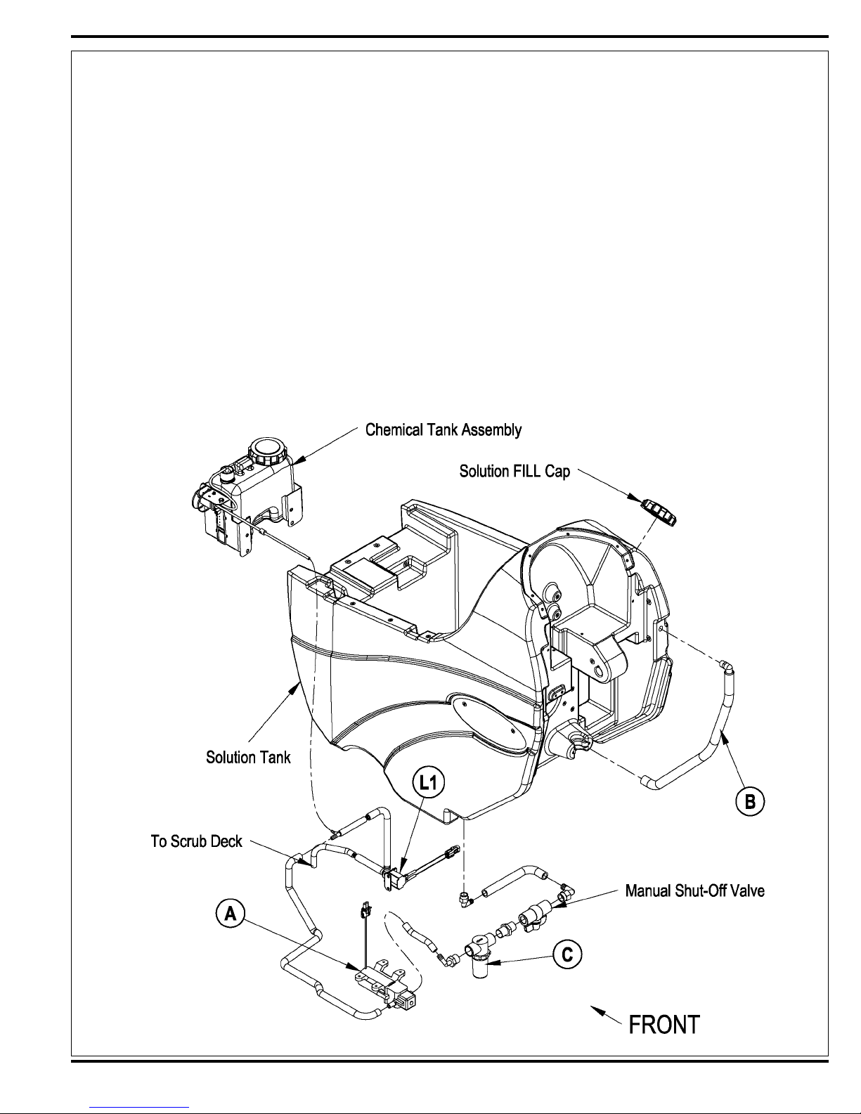
FUNCTIONAL OVERVIEW
See Figure 1. The Convertamatic models have a solution tank fi ll capacity of 20-gallons (76 liters). All models use one right rear tank fi ll opening, which offers ease
of fi lling. Plumbed into the manual solution shut off valve outlet is a serviceable Solution Filter (C), to keep debris from entering the solenoid valve. Also fi tted to the
tank is a fl exible Clear Hose (B) used to indicate the solution level and to drain the tank for system maintenance.
The standard solution system uses an electrical Solenoid Valve (L1) which stops and starts the solution fl ow to the scrub brushes. The M7 water pump (A) located on
the machine chassis controls the needed fl ow volume demand to the scrub brushes. See Electrical Diagram Figure 2. The electrical circuit that turns on (energizes)
the solenoid coil and water pump is activated through the (A1) control panel’s solution switch button input and the FWD / REV (A2) Speed Controller voltage output
signals. Note: See the Know Your Machine section in this manual for a complete explanation of the solution operation modes.
During normal machine scrubbing the solution system’s Auto Mode is selected and works in conjunction with the wheel drive speed controller and the (A1) main
controller’s scrub system outputs to turn On & Off the (L1) solenoid valve and pump. The solution will fl ow to the scrub brushes when the scrub deck is lowered and
the handle drive paddle (box) is pushed Fwd. Note: When the solution On/Off button is turned Off, no fl ow can occur while the machine scrub deck is down and the
drive paddle activated.
*Note: Figure 1 shows the solution components of a machine with the Chemical System. The Chemical Tank Assembly is not found on all models.
FIGURE 1
FORM NO. 56043098 - Convertamatic™ 24C, 24D, 26C, 26D, 28C, 28D - 13
SOLUTION SYSTEM
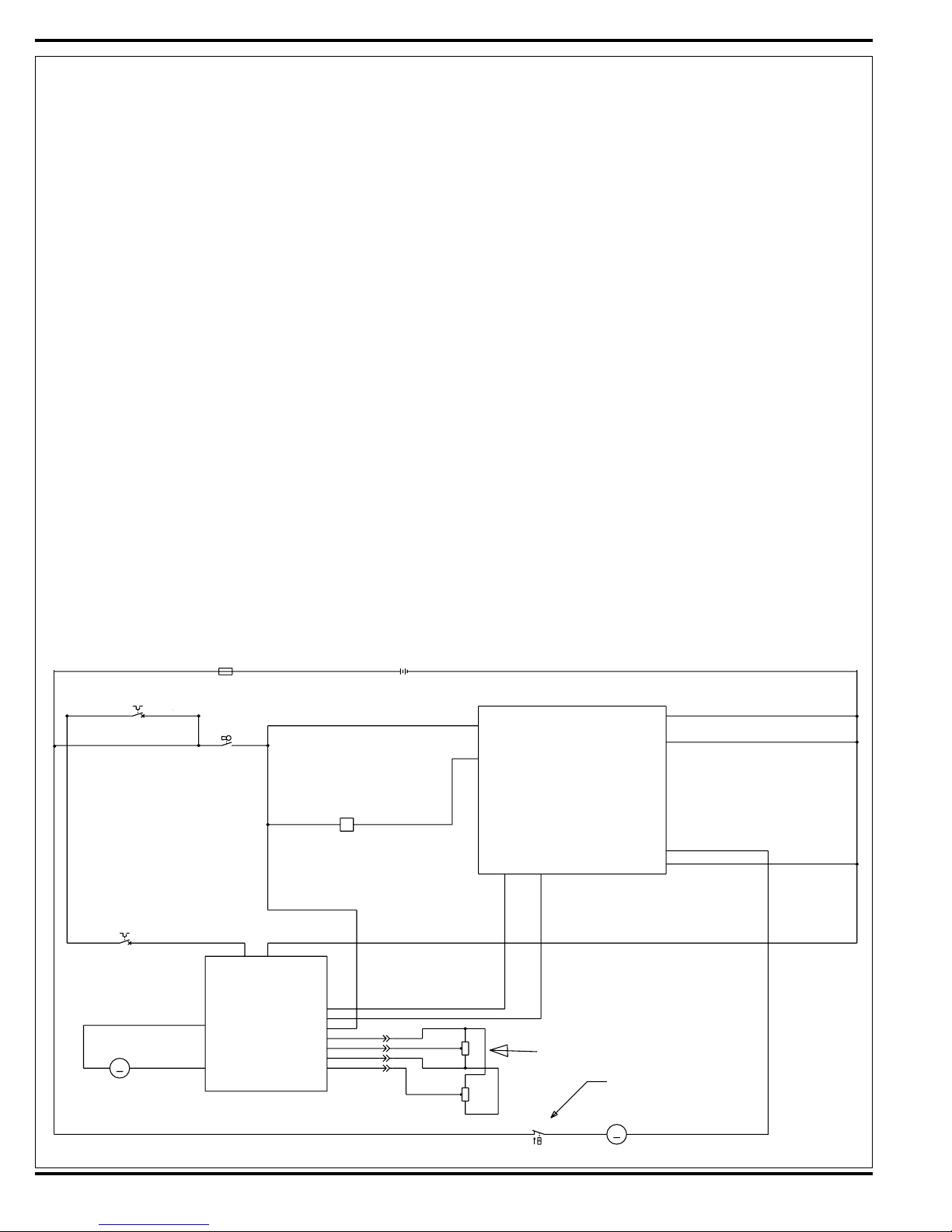
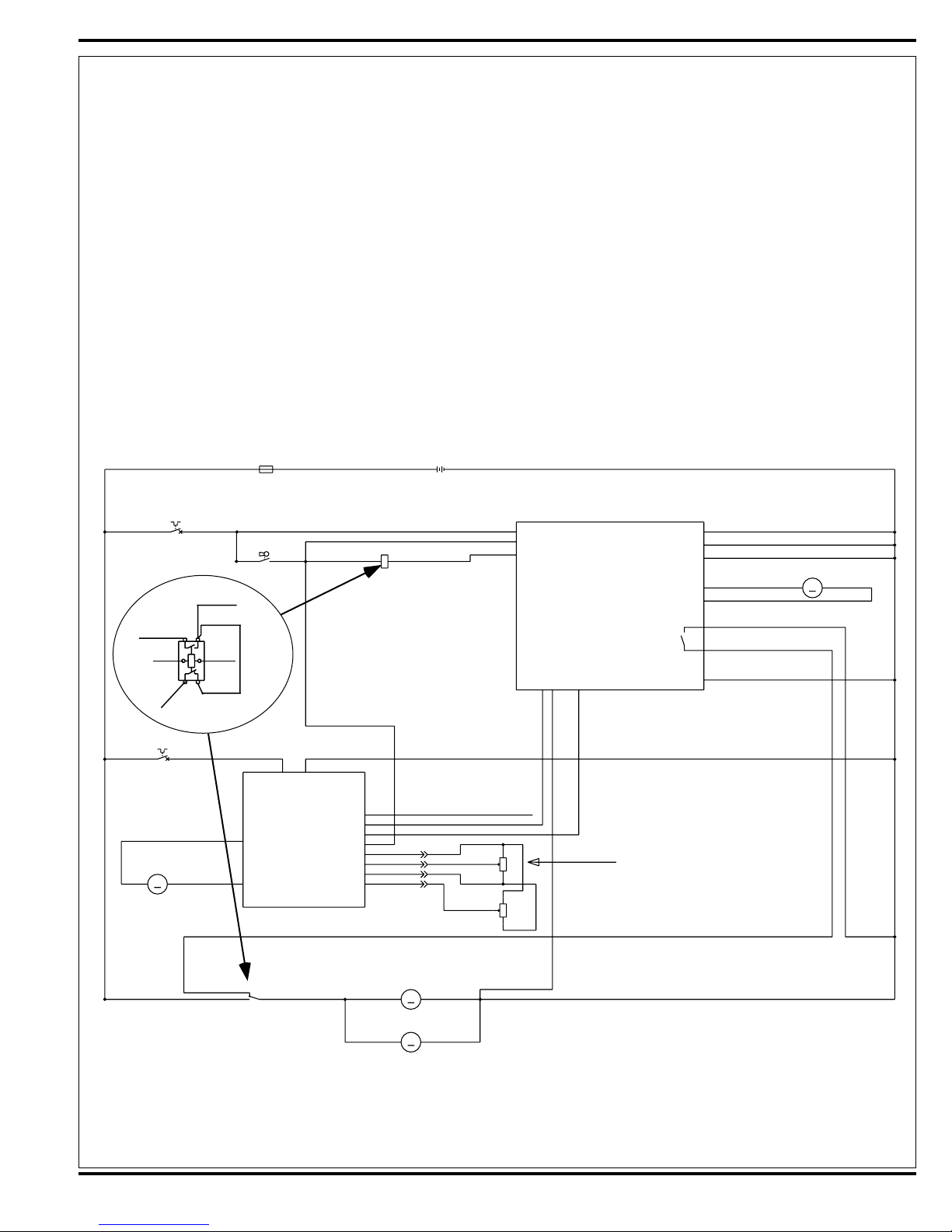
CIRCUIT OVERVIEW SOLUTION AUTO MODE (SOLENOID VALVE CIRCUIT)
See Figure 2.
+ (Positive) circuit input starts with:
• A closed S3 key switch will direct the needed positive voltage (BRN wires) to the L1 solenoid coil and A1 control board terminal #J1-13.
- (Negative) circuit input starts with:
• A battery negative ground input at the A1 control board terminal #B2 (J1-9)
• The A1 control board solution button enabled.
• A negative voltage output from the A2 speed controller’s (pin #6) Red/Blk wire to the A1 control board Red/Blk wire (terminal J1-5). Note: The A2 speed controls
brake output (pin #6) occurs whenever the R1 direction throttle pot is moved off its neutral setting.
• A negative voltage output from the A1 board’s terminal J1-11 Red/Grn wire is direct to the L1 solenoid coil turning it on to allow fl ow through the valve body.
CIRCUIT OVERVIEW SOLUTION AUTO MODE (SOLUTION PUMP CIRCUIT)
See Figure 2.
+ (Positive) circuit input starts with:
• With the batteries connected the needed positive voltage (Red wires) to the M7 Solution Pump.
- (Negative) circuit input starts with:
• A battery negative ground input at the A1 control board terminal #B4 (J2-6)
• The A1 control board solution button enabled.
• A negative voltage output from the A2 speed controller’s (pin #6) Red/Blk wire to the A1 control board Red/Blk wire (terminal J1-5). Note: The A2 speed controls
brake output (pin #6) occurs whenever the R1 direction throttle pot is moved off its neutral setting.
• A negative voltage output from the A1 board’s terminal J1-8 Grn/Blk wire is direct to the M7 Solution Pump turning it on to allow fl ow to the L1 Water Valve
Solenoid. NOTE: The solution pump’s output volume is controlled by the A1 board’s programmable capability and changes the pulsing of the negative battery
connection to the pump.
Electrical Diagram
*For complete description of all callouts see Electrical System Wiring Diagram.
FIGURE 2
RED
F2
12
RED
CIRCUITBREAKER,5AMP
F3
12
RED
CIRCUITBREAKER,30AMP
1210SPEEDCONTROLLER
MOTOR,WHEELDRIVE
-
M1
M
(1228FOR36V)
+
BRN/BLK
YEL/RED
GRN
A2
RED
12
FUSE,150A.
SW,SPSTKEY
WHT/YEL
M1
M2
F1
S3
RE
BRN
COIL,SOLUTIONSOLENOID
B+ B-
PIN9-STATUS
PIN6-BRAKE(-)
PIN16-REV
PIN5-KSI
PIN13-POT.LO
PIN4-POT.WIPER
PIN3-POT.HI
PIN18-SPEEDLIMITPOT
D
24VDCOR36VDC
BRN
L1
12
BLK
BRN
WHT
BLU
BLK
BRN
POT.100KOHMSPEEDLIMIT
BATT
RED/GRN
RED/BLK
BLU/BLK
BT1
+-
ERY
BLU
BRN
WHT
BLK
BLK
J1-13
J1-11
B+1
SOLUTION
A1
J1-9
B-2
J2-6
B-4
BLK
BLK
CONTROLBOARD
J1-8
SOL.PUMP
J1-7
FOR/REV.
REVERSE
J1-5
J1-6
RED/BLK
BLU/BLK
1
2
WHT
3
1
R2
2
3
BLK
12
R1
POT.5KOHMTHROTTLE
S1
B-1
NOTE:SWITCHISPARTOF
PUMPASSEMBLY
M7
-+
M
SOLUTIONPUMP
BLK
GRN/BLK
GRN/BLK
14 - FORM NO. 56043098 - Convertamatic™ 24C, 24D, 26C, 26D, 28C, 28D

SOLUTION SYSTEM
SOLUTION SYSTEM MAINTENANCE
• Solution Tank: See Figure 1. Weekly empty the solution tank; remove the solution Drain Hose (B) from its storage area (located on the right rear control handle
compartment). Direct the hose to a designated “Disposal Site” and fl ush the tank with clean water.
• Solution Filter: Remove and clean the inline Solution Filter (C). To access the fi lter housing for removal, work underneath the middle left side chassis panel. No
tools are needed to remove the fi lter (hand tighten only). Service Tip: The solution fi lter ball valve must be placed in the OFF (Closed) position. This prevents loss
of solution when servicing the fi lter strainer with a partial or full tank.
• Solution Delivery Trough: On the cylindrical scrub deck clean the holes in the delivery trough to assure even distribution of solution.
TROUBLESHOOTING GUIDE
Problem Possible Cause
Inadequate or no solution fl ow No solution in the tank
Solution tank fi lter ball valve in the off position
Clogged solution fi lter, valves and hoses
*Reference the Solution System Troubleshooting Guide fl owchart in this manual section for further component diagnostics.
FORM NO. 56043098 - Convertamatic™ 24C, 24D, 26C, 26D, 28C, 28D - 15
SOLUTION SYSTEM
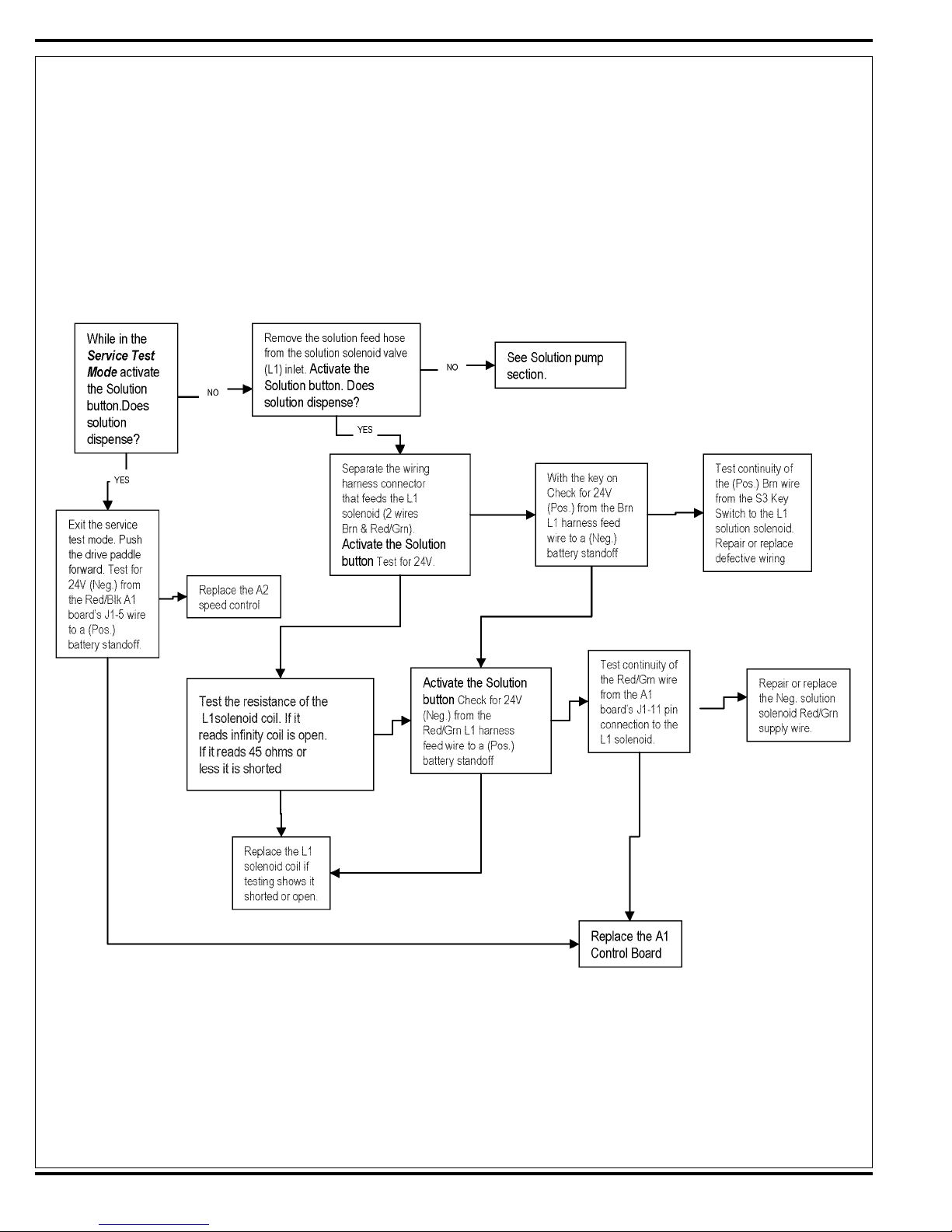
TROUBLESHOOTING GUIDE ELECTRICAL
Possible Symptoms
1-No solution fl ow while in the scrub auto solution mode.
2-Solution Pump will not operate:
SYMPTOM ONE
Note: Activate the Service Test Mode Program. See optional program section for instructions.
All testing will be performed in the Service Test Mode Program.
16 - FORM NO. 56043098 - Convertamatic™ 24C, 24D, 26C, 26D, 28C, 28D
SOLUTION SYSTEM
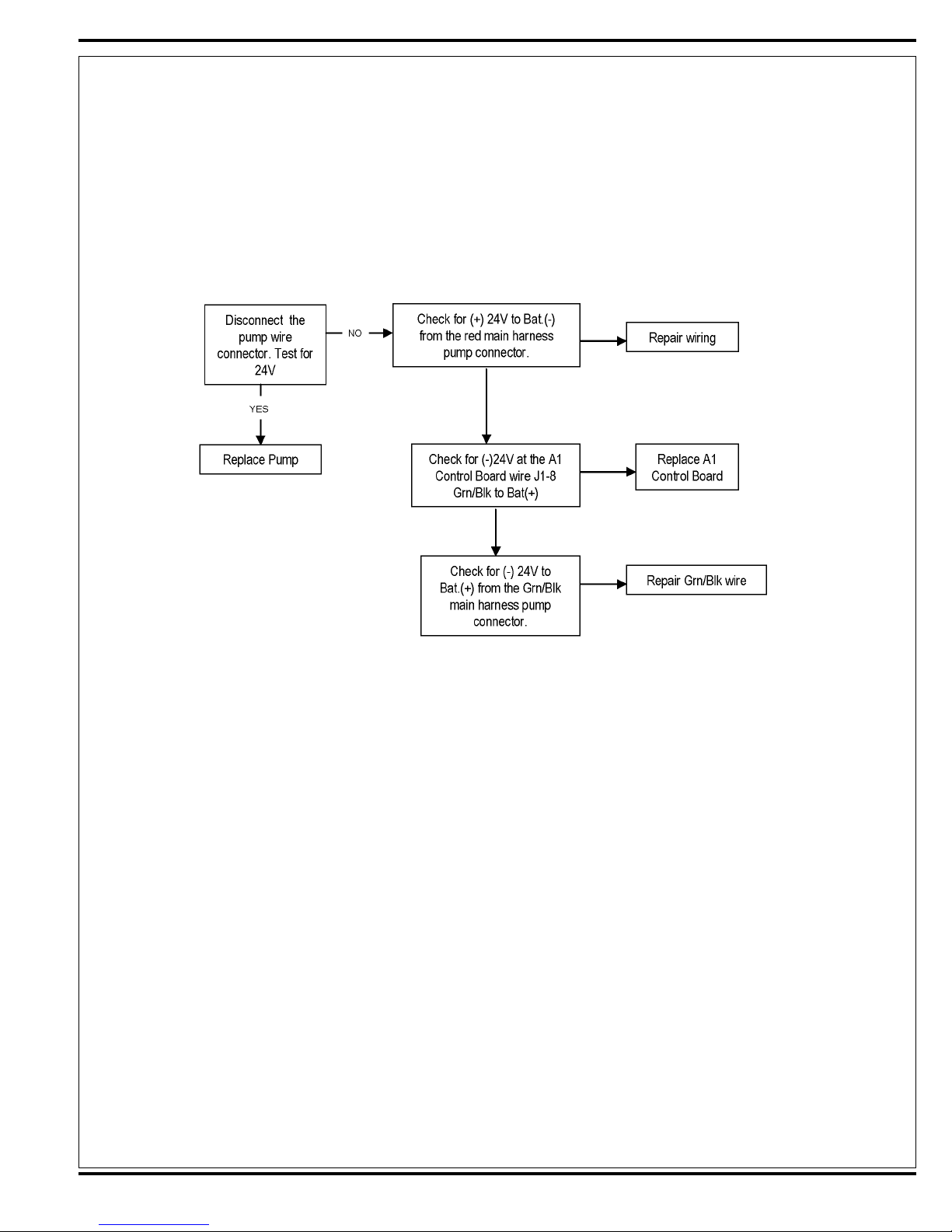
TROUBLESHOOTING GUIDE ELECTRICAL (CONTINUED)
SYMPTOM TWO
Note: Activate the Service Test Mode Program. See optional program section for instructions.
All testing will be performed in the Service Test Mode Program.
FORM NO. 56043098 - Convertamatic™ 24C, 24D, 26C, 26D, 28C, 28D - 17
SOLUTION SYSTEM
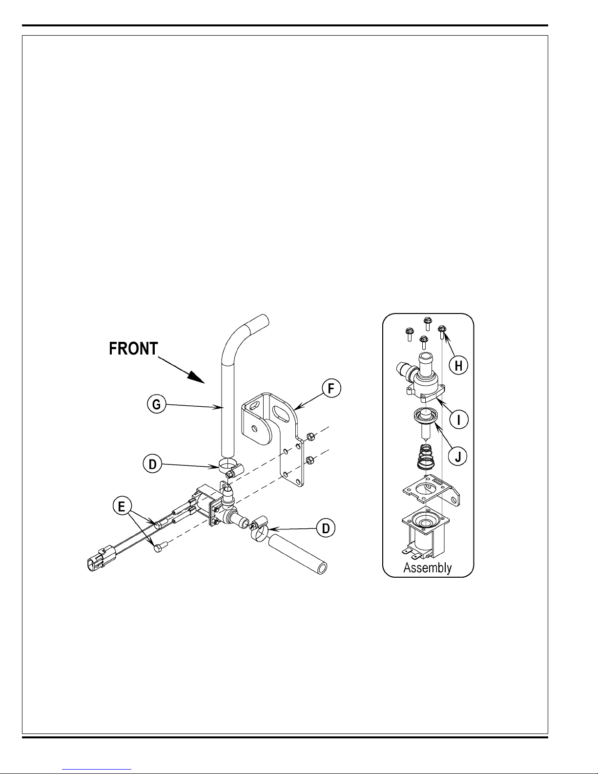
SOLENOID VALVE REMOVAL
1 Drain the solution tank or turn the solution fi lter ball valve to the off position to prevent solution loss.
2 Lower the deck and disconnect the battery supply to the machine.
3 Remove the front Nose Cone from the machine by fi rmly grasping the lower part and lifting straight up.
4 See Figure 3. Unplug the L1 solenoid valve wire assembly connection from the machine harness.
5 Unscrew the inlet Hose Clamps (D) that secure the hoses to the valve body.
6 Separate (pry) the solution outlet hose off from its valve body barbed fi tting.
7 Remove the (2) Hex Screws (E) that secure the valve to the Mount Bracket (F), then pull the valve body to the front separating it from the solution inlet Hose
(G), completing the part removal.
SOLENOID VALVE DISASSEMBLY AND CLEANING
1 Remove the solenoid valve. See the Solenoid Valve Removal section for instructions.
2 See Figure 3. Remove the (4) (H) Screws and disassemble the valve (be careful not to lose any internal parts).
3 Thoroughly wash dirt from block (I) and diaphragm (J).
4 After reassembling, test the solenoid valve for proper operation.
FIGURE 3
18 - FORM NO. 56043098 - Convertamatic™ 24C, 24D, 26C, 26D, 28C, 28D
SOLUTION SYSTEM
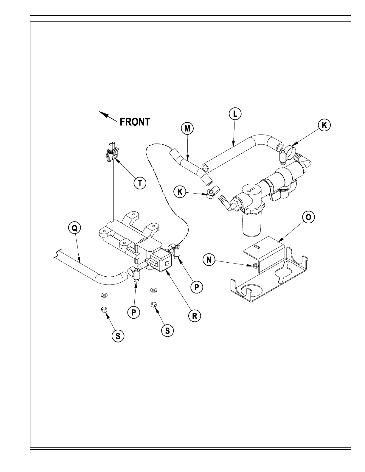
SOLUTION FILTER AND BALL VALVE REMOVAL
1 Drain the solution tank using the solution drain hose (B).
2 See Figure 4. Loosen the (2) Hose Clamps (K) and pry off the inlet Solution Hose (L) and Solution Hose (M).
3 Remove the Nut (N) that secures the Filter Mount Bracket (O) to the chassis and remove the assembly from the machine.
FIGURE 4
SOLUTION PUMP REMOVAL
1 Drain the solution tank or turn the solution fi lter ball valve to the off position to prevent solution loss.
2 See Figure 4. Loosen the (2) Hose Clamps (P) and pry off inlet Hose (M) and outlet Hose (Q) from Solution Pump (R).
3 Remove the (2) 10-24 nuts (S) that secure the Solution Pump to the Chassis.
4 Disconnect the Solution Pump Electrical Connector (T); (A tie strap may need to be cut) completing the part removal.
NOTE: Refer to the APPENDIX at the back of this manual for solution system fl ow schematics and detergent system information.
FORM NO. 56043098 - Convertamatic™ 24C, 24D, 26C, 26D, 28C, 28D - 19

SCRUB SYSTEM
FUNCTIONAL OVERVIEW
• Disc Brush System Overview
See Figure 2. The machine models Convertamatic™ 24D, 26D, 28D use the disc type scrub system powered by (2) 1/2 hp motor gearbox assemblies.
• Cylindrical Brush System Overview
See Figure 4. The machine models Convertamatic™ 24C, 26C, 28C use two cylindrical brushes that counter rotate to sweep up light debris and scrub at the same
time. Each scrub brush is powered on opposing ends by 1/2 HP permanent magnet motors attached to separate poly-V belt/pulley drives.
• General Brush Overview
Note: Recovery Tank Full switch must be closed (Tank empty). On all models the scrub deck platform is raised & lowered automatically by a vertically mounted
electric lift actuator motor. The operation of the machine’s scrub functions are activated when the operator selects (presses) the scrub on (mode) panel button. The
scrub pad or brush pressure ranges (1-3) are selectable allowing the operator the choice to vary the scrubbing effort (pressure) while operating the machine. Note:
See the Main Control Board Special Program Options section in this manual for more detailed operation and instructions to change scrub pressure settings.
See Figure 1. The machine’s main scrub system input and output operating functions are regulated (managed) by the display panel and combined main control
board A1. The major scrub system functions are…
• M2 / M3 - Scrub Brush Motor Run Function
Circuit Overview Scrub Brush Motor
+ (Positive) Circuit input starts with:
• A closed S3 key switch supplies the needed positive voltage to the K1 brush solenoid coil and the A1 control board #J1-13 (Brn wire). Note: The A1 control
board scrub-on button must also be depressed (enabled). This operator command lowers the brush deck.
Once the K1 load is closed the needed Positive voltage is supplied to the motors M2 and M3.from battery Pos.
- (Negative) Circuit input starts with:
• A battery negative ground input at the A1 control board terminals B2 (J1-9) Blk and B1 (J1-7) Blk.
• Note: The A1 control board scrub-on button must also be depressed (enabled).
• A negative voltage output from the A2 speed controller’s Neg. (pin #6) Red/Blk wire to the A1 control board Red/Blk wire (terminal J1-5). Note: The A2 speed
control brake output (neg.) (pin #6) occurs whenever the R1 direction throttle pot is moved off its neutral setting.
• A negative voltage output from the A1 board’s terminal (J1-14) Vio/Blk wire completes the K1 solenoid coil circuit (Pos. & Neg.) and pulls in the load contact
making the brush motors run.
The Neg. M2 and M3 load voltage is supplied from the battery Neg.
• M5 - Scrub Brush Actuator Lift Motor Function
The A1 control board outputs a controlled motor voltage polarity change (wires J2-1 and J2-8) that raises and lowers the scrub-deck for installing, removing and
controlling the scrub brushes’ selected current load. The large BLK negative (-) scrub brush motor wire is specially designed so that it has a known (specifi ed)
resistance value. As brush motor current passes through the negative wire that is, in effect, a low value resistor, a small voltage drop is developed across it which
is proportional to the motor current. This voltage change is inputted to the A1 control board at J2-5 and J1-7(sense wires WHT/GRA & BLK). Any surrounding
temperature change in this large Neg. motor wire affects its resistance so the temperature is sensed by a thermistor (*) built into the control board A1. This allows
the controller to provide error correction for the temperature resistance changes. When the controller senses a current draw out of the desired range it automatically
turns on the M5 actuator motor to raise or lower the scrub deck. This process is on going in maintaining the operator’s selected scrub motor current load setting to
sustain the desired brush working pressure.
• Scrub System Low Voltage Cut-Out Function
The purpose of the special low battery voltage cutout function is to help prolong battery life. The scrub deck will be raised and the brush motors and solution solenoid
valve will turn OFF automatically and cease to function when the batteries discharge to the selected cutout level. The cutout level is adjustable between two settings.
The standard setting (wet cell/lead acid) is 1.72 volts per cell and alternate setting (gel/maintenance free) is 1.81 volts per cell. Note: See the battery system section
for instructions for selecting (setting) the two different thresholds.
SPECIAL SCRUB SYSTEM FUNCTIONS
• Scrub Brush Removal Function (Disc only)
For removal of the scrub brushes automatically, the scrub deck must be in the up position and the drive system in neutral. To remove the scrub brushes simply
depress the control panel scrub-off button (H) for 2-3 seconds. The A1 control board will momentarily run the brush motors and then stop them quickly, where the
brushes inertia causes the brushes to easily spin off of the scrub brush motors drive caps.
20 - FORM NO. 56043098 - Convertamatic™ 24C, 24D, 26C, 26D, 28C, 28D
SCRUB SYSTEM
• Scrub Brush Removal Function (Continued / Disc only)
• Control and Load circuit detail.
A closed S3 key switch supplies the needed positive voltage to the K1 brush solenoid coil, A1 control board (J1-13) Brn wire and K3 brush remove coil relay
(Part of A1 Control Board).
- The brush remove circuit sequence starts when the operator depresses the control panel scrub off button (H) for 2-3 seconds activating the A1 board’s brush
remove function. This triggers (starts) an internal timer relay closing the K1 coil ground circuit, pin (J1-14) Vio/Blk wire turning on momentarily the brush
solenoid to run the brush motors.
- Simultaneously with the K1 coil being turned on the same input command closes the K3 coil (Part of A1 Control Board) turning it ON.
- This pulls in the K3 load contacts (Part of A1 Control Board) connecting it to the battery ground through the A1 Brush Remove circuit N.O. Blk wire and Common
Blu/Wht wire to K1 Load Contactor N.C
- The next step is the board timer turning off the K1 brush solenoid and connecting the normally Pos. motor load circuit to a battery ground, sending a neg.
voltage from the K3 Relay (Part of A1 Control Board) though the Blu/Wht N.O. wire. When K1 is de-energized the neg. voltage from the K3 relay is connected
to the Brush Motors Positive Wht. wires through a Red/Wht jumper wire connected to the K1 N.C.
- With two battery ground inputs at the brush motors this circuit causes a short to ground and the motors stop abruptly. The built up brushes inertia easily spins
the brushes off the motors drive disc lugs.
FIGURE 1
RED
F2
12
RED
CIRCUIT BREAKER, 5AMP
K1
WHT
RED
BRN
VIO/BLK
BLU/WHT
GRN
F1
12
FUSE,150A.
S3
SW,SPSTKEY
RED/WHT
GRN
RED
BRN
K1
BRN
COIL
BRUSH MOTOR CONTACTOR
BT1
+-
BATTERY
24VDC OR 36VDC
VIO/BLK
A1
CONTROLBOARD
J2-7
B+2
J1-13
B+1
J1-14
BRUSHCONTACTOR
J1-5
BLK
J1-3
J2-3
J2-2
INPUT
SUPPLY
BRUSH ACTUATOR-2
BRUSH ACTUATOR-1
K3
BRUSH
REMOVE RELAY
FOR/REV.
BRUSH MOTOR SENSE
REVERSE
J2-5
J1-6
J2-9
B-3
J2-6
B-4
J2-1
J2-8
RELAY N.O.
RELAY COMMON
J1-7
B-1
J1-9
B-
B-2
BLK
BLK
BLK
M5
VIO/YEL
WHT/GRN
MOTOR, BRUSH ACTUATOR
BLK
M
F3
12
RED
CIRCUIT BREAKER, 30AMP
1210 SPEED CONTROLLER
(1228 FOR 36V)
BRN/BLK
M1
+
-
MOTOR, WHEEL DRIVE
RED
YEL/RED
M
BLU/WHT
WHT/YEL
A2
M1
M2
K1
BLK
B+ B-
PIN9-STATUS
PIN6-BRAKE(-)
PIN16-REV
PIN5-KSI
PIN13-POT.LO
PIN4-POT.WIPER
PIN18-SPEED LIMIT POT
PIN3-POT.HI
WHT
BRN
ORN/BLU
RED/BLK
BLU/BLK
WHT
BLU
BLK
BRN
POT. 100K OHM SPEED LIMIT
POLARITY FOR DISC BRUSHES
WHT
WHT
M2
+
M
MOTOR, LEFT BRUSH
M3
-+
M
MOTOR, RIGHT BRUSH
BLU
BRN
-
BLK
BLK
WHT
BLK
2
2
1
WHT
3
1
R2
3
WHT/GRA
BLK
WHT/GRA
RED/BLK
BLU/BLK
R1
POT.5KOHMTHROTTLE
BLU/WHT
BLK
BLK
BLU/WHT
BLK
FORM NO. 56043098 - Convertamatic™ 24C, 24D, 26C, 26D, 28C, 28D - 21
SCRUB SYSTEM
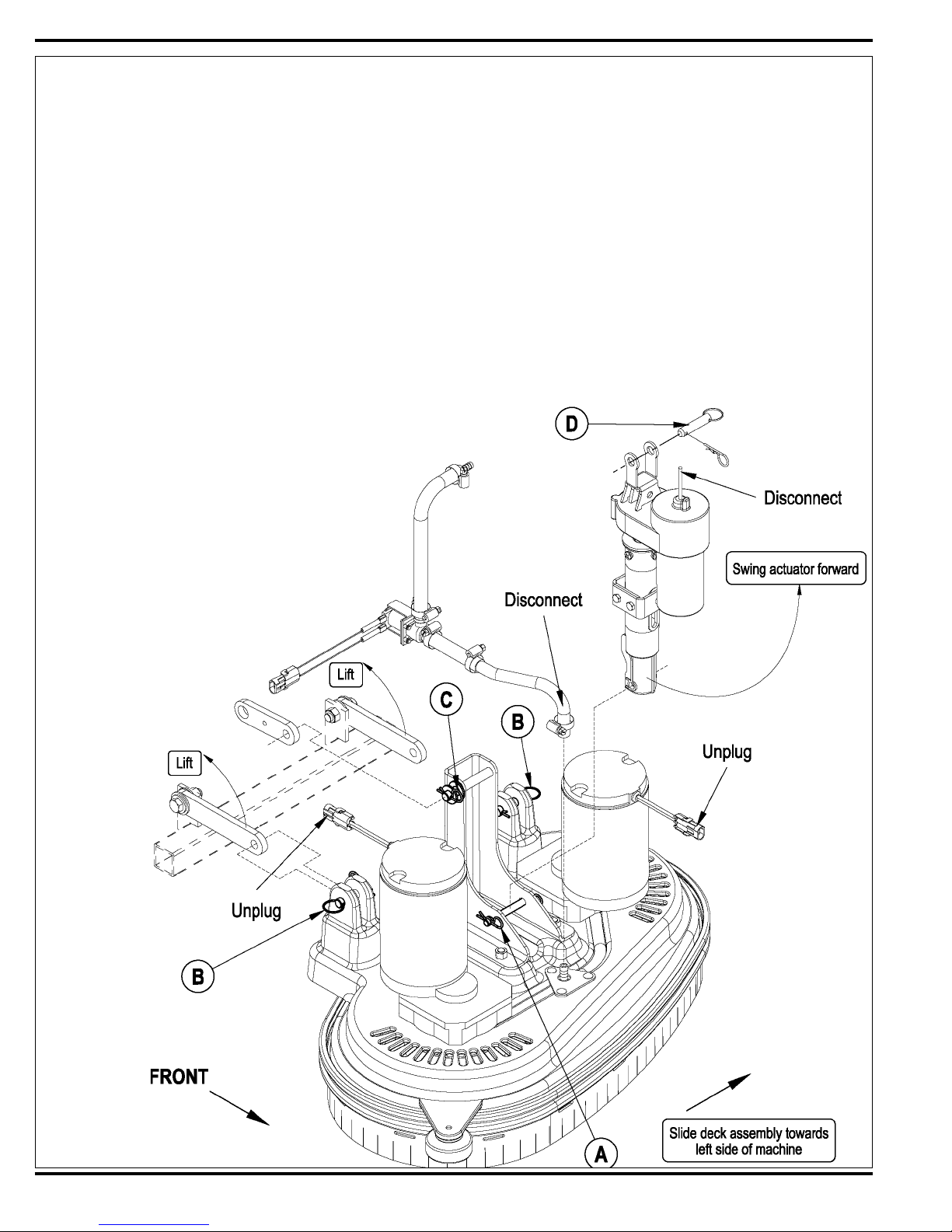
SCRUB BRUSH DECK REMOVAL (DISC)
1 With scrub brushes installed lower the scrub deck, turn the key off and disconnect the battery pack.
2 Remove the front Nose Cone by fi rmly grasping the lower part and lifting straight up.
3 Disconnect the Solution Hose from the scrub deck.
4 Unplug both brush motor wire assemblies. Note: Cable ties may need to be cut.
5 See Figure 2. Remove the lower Actuator Mount Pin (A). Note: Lift up on the scrub deck to take pressure off the Pin (A). Service Note: It is important that
the actuator motor is not run while it is disconnected from the deck or chassis mounts. This precaution will prevent the actuator drive nut from being
misadjusted (moved out of its set specifi cation).
6 Remove the left and right rear deck pins (B) and Cotter Hair Pin (C).
7 Carefully slide the Scrub Deck to the left and then towards the front.
8 To reinstall a scrub deck, follow the above steps in reverse order.
SCRUB BRUSH LIFT ACTUATOR REMOVAL (DISC.)
1 With scrub brushes installed, lower the scrub deck, turn the key off and disconnect the battery pack. Note: If the lift actuator motor will not run go to step 2 and
perform the following, shim up the brush deck to remove the weight on the lower deck Actuator Pin (A) to remove.
2 Remove the front nose cone by fi rmly grasping the lower part and lifting straight up.
3 Disconnect the actuator motor wiring harness pig tail connector.
4 Remove the lower actuator mount Pin (A). Note: Lift up on the scrub deck to take pressure off the pin (A).
5 Remove the Pin (D) from the upper actuator mount weldment and remove the motor.
6 See *Important Service Note below.
7 Reinstall in reverse order.
*Important Service Note: After removing any actuator motor and before
installing a new motor or drive nut the IN and OUT limit switches must be
set (or checked) to their correct specifi cations. Reference the Electrical
System in this manual for the Actuator Drive Nut Adjustment and follow
these instructions before replacing the actuator motor.
After setting the correct actuator nut adjustments for the scrub brush lift
motor, follow removal steps in reverse order to reassemble.
FIGURE 2
22 - FORM NO. 56043098 - Convertamatic™ 24C, 24D, 26C, 26D, 28C, 28D
 Loading...