

Advance acoustic Adfinity 20ST, Adfinity 20D, AdfinityX20D, Adfinity X20R, 908 7161 020 Pressure Washer
...
TM
Adnity
17ST / 20ST
20D / X20D / X20C / X24D
SERVICE MANUAL
Advance model: 908 7161 020 - 908 7162 020
- 908 7163 020 - 908 7164 020 - 908 7165 020
- 908 7166 020
9096982000(1)2007-02

ENGLISH
SERVICE MANUAL
2
9096982000(1)2007-02 AdnityTM 17 ST, 20 ST, 20 D, X 20 D, X 20 C, X 24 D

SERVICE MANUAL
ENGLISH
TABLE OF CONTENTS
GENERAL INFORMATION ......................................................................................................................................... 5
CONVENTIONS ..................................................................................................................................................... 5
MACHINE LIFTING ................................................................................................................................................ 5
MACHINE TRANSPORTATION ............................................................................................................................. 5
OTHER REFERENCE MANUALS ......................................................................................................................... 5
SAFETY ................................................................................................................................................................. 5
SYMBOLS .............................................................................................................................................................. 5
GENERAL INSTRUCTIONS .................................................................................................................................. 5
TECHNICAL DATA (For AdnityTM 17 ST, 20 ST) ...................................................................................................7
TECHNICAL DATA (For AdnityTM 20 D, X 20 D, X 20 C, X 24 D) ......................................................................... 8
MAINTENANCE ..................................................................................................................................................... 9
SCHEDULED MAINTENANCE TABLE ................................................................................................................. 9
MACHINE NOMENCLATURE (For AdnityTM 17 ST, 20 ST) ................................................................................ 10
MACHINE NOMENCLATURE (For AdnityTM 20 D, X 20 D, X 20 C, X 24 D) ...................................................... 12
SOLUTION/CLEAN WATER SUPPLY SYSTEM ...................................................................................................... 15
SOLUTION/CLEAN WATER TANK AND SUPPLY SYSTEM CLEANING ............................................................ 15
SOLUTION FILTER CLEANING (For AdnityTM 17 ST, 20 ST) ............................................................................ 15
SOLUTION FILTER CLEANING (For AdnityTM 20 D) ......................................................................................... 16
SOLENOID VALVE DISASSEMBLY/ASSEMBLY (For AdnityTM 17 ST, 20 ST) ................................................. 16
SOLENOID VALVE DISASSEMBLY/ASSEMBLY (For AdnityTM 20 D, X 20 D, X 20 C, X 24 D)......................... 17
TROUBLESHOOTING ......................................................................................................................................... 17
AXP .......................................................................................................................................................................... 19
CLEAN WATER FILTER CLEANING (For AdnityTM X 20 D, X 20 C, X 24 D) ..................................................... 19
DETERGENT TANK CLEANING (For AdnityTM X 20 D, X 20 C, X 24 D) ........................................................... 20
AXP DRAINING (For AdnityTM X 20 D, X 20 C, X 24 D) ..................................................................................... 20
WATER PUMP DISASSEMBLY/ASSEMBLY (For AdnityTM X 20 D, X 20 C, X 24 D) ......................................... 21
DETERGENT PUMP AND CHECK VALVE DISASSEMBLY/ASSEMBLY
(For AdnityTM X 20 D, X 20 C, X 24 D) ................................................................................................................ 21
TROUBLESHOOTING ......................................................................................................................................... 23
BRUSHING SYSTEM ................................................................................................................................................ 25
BRUSH/PAD CLEANING ..................................................................................................................................... 25
BRUSH/PAD-HOLDER/CYLINDRICAL BRUSH DECK DISASSEMBLY/ASSEMBLY
(For AdnityTM 17 ST, 20 ST) ................................................................................................................................ 25
BRUSH/PAD-HOLDER/CYLINDRICAL BRUSH DECK DISASSEMBLY/ASSEMBLY
(For AdnityTM 20 D, X 20 D, X 20 C, X 24 D) ...................................................................................................... 26
BRUSH MOTOR ELECTRICAL INPUT CHECK (For AdnityTM 17 ST, 20 ST) .................................................... 27
BRUSH MOTOR ELECTRICAL INPUT CHECK (For AdnityTM 20 D, X 20 D) .................................................... 28
BRUSH MOTOR ELECTRICAL INPUT CHECK (For AdnityTM X 20 C) .............................................................. 30
BRUSH MOTOR ELECTRICAL INPUT CHECK (For AdnityTM X 24 D) .............................................................. 31
BRUSH MOTOR CARBON BRUSH CHECK/REPLACEMENT (For AdnityTM 17 ST, 20 ST) ............................. 32
BRUSH MOTOR CARBON BRUSH CHECK/REPLACEMENT (For AdnityTM 20 D, X 20 D) ............................. 33
BRUSH MOTOR CARBON BRUSH CHECK/REPLACEMENT (For AdnityTM X 20 C) ....................................... 35
BRUSH MOTOR CARBON BRUSH CHECK/REPLACEMENT (For AdnityTM X 24 D) ....................................... 36
BRUSH MOTOR DISASSEMBLY/ASSEMBLY (For AdnityTM 17 ST, 20 ST, 20 D, X 20 D) ................................ 37
BRUSH MOTOR DISASSEMBLY/ASSEMBLY (For AdnityTM X 20 C) ................................................................ 38
BRUSH MOTOR DISASSEMBLY/ASSEMBLY (For AdnityTM X 24 D) ................................................................ 39
CHECK/REPLACEMENT/ADJUSTMENT OF DRIVING BELTS FROM MOTORS
TO CYLINDRICAL BRUSHES (For AdnityTM X 20 C) ......................................................................................... 40
BRUSH ENABLING MICROSWITCH ADJUSTMENT/REPLACEMENT
(For AdnityTM 20 D, X 20 D, X 20 C, X 24 D) ...................................................................................................... 41
TROUBLESHOOTING ......................................................................................................................................... 42
AdnityTM 17 ST, 20 ST, 20 D, X 20 D, X 20 C, X 24 D 9096982000(1)2007-02
3

ENGLISH
SERVICE MANUAL
RECOVERY WATER SYSTEM ................................................................................................................................. 43
RECOVERY WATER TANK AND VACUUM GRID CLEANING, AND COVER GASKET CHECK ....................... 43
SQUEEGEE CLEANING/CHECK/REPLACEMENT AND SQUEEGEE BLADE REPLACEMENT ...................... 44
VACUUM SYSTEM MOTOR FILTER CLEANING ............................................................................................... 45
VACUUM SYSTEM MOTOR ELECTRICAL INPUT CHECK ................................................................................ 45
VACUUM SYSTEM MOTOR CARBON BRUSH CHECK/REPLACEMENT ........................................................ 46
VACUUM SYSTEM MOTOR DISASSEMBLY/ASSEMBLY .................................................................................. 17
SQUEEGEE SPRING CHECK/REPLACEMENT (All models, with aluminium squeegee) .................................. 48
TROUBLESHOOTING ......................................................................................................................................... 48
DRIVE SYSTEM ........................................................................................................................................................ 49
SPEED POTENTIOMETER ADJUSTMENT/REPLACEMENT (For AdnityTM 20 D, X 20 D, X 20 C, X 24 D) .... 49
MAXIMUM SPEED POTENTIOMETER DISASSEMBLY/ASSEMBLY
(For AdnityTM 20 D, X 20 D, X 20 C, X 24 D) ...................................................................................................... 51
DRIVE SYSTEM MOTOR ELECTRICAL INPUT CHECK
(For AdnityTM 20 D, X 20 D, X 20 C, X 24 D) ...................................................................................................... 52
DRIVE SYSTEM MOTOR CARBON BRUSH CHECK AND REPLACEMENT
(For AdnityTM 20 D, X 20 D, X 20 C, X 24 D) ...................................................................................................... 53
DRIVE SYSTEM MOTOR-DIFFERENTIAL DISASSEMBLY/ASSEMBLY
(For AdnityTM 20 D, X 20 D, X 20 C, X 24 D) ...................................................................................................... 54
TROUBLESHOOTING ......................................................................................................................................... 55
DRIVE SYSTEM ELECTRONIC BOARD DIAGNOSTIC TABLE ......................................................................... 56
OTHER SYSTEMS .................................................................................................................................................... 57
SCREW AND NUT TIGHTENING CHECK ........................................................................................................... 57
ELECTRICAL SYSTEM ............................................................................................................................................ 59
MACHINE WORKING HOUR CHECK (with optional hour counter) .................................................................... 59
BATTERY CHARGE AND MAINTENANCE (All models) ..................................................................................... 59
BATTERY DISASSEMBLY/ASSEMBLY ............................................................................................................... 59
BATTERY TYPE SETTING (WET OR GEL) (For AdnityTM 17 ST, 20 ST) .......................................................... 60
BATTERY TYPE SETTING (WET OR GEL) (For AdnityTM 20 D, X 20 D, X 20 C, X 24 D) ................................60
FUSE CHECK/REPLACEMENT .......................................................................................................................... 61
BRUSH MOTOR ELECTROMAGNETIC SWITCH DISASSEMBLY/ASSEMBLY ................................................ 62
DRIVE SYSTEM ELECTRONIC BOARD DISASSEMBLY/ASSEMBLY
(For AdnityTM 20 D, X 20 D, X 20 C, X 24 D) ...................................................................................................... 63
FUNCTION ELECTRONIC BOARD DISASSEMBLY/ASSEMBLY ....................................................................... 64
TROUBLESHOOTING ......................................................................................................................................... 64
COMPONENT LAYOUT (For AdnityTM 17 ST, 20 ST) ......................................................................................... 65
WIRING DIAGRAM (For AdnityTM 17 ST, 20 ST) ................................................................................................ 66
COMPONENT LAYOUT (For AdnityTM 20 D, X 20 D, X 20 C, X 24 D) ............................................................... 67
WIRING DIAGRAM (For AdnityTM 20 D, X 20 D, X 20 C, X 24 D) ...................................................................... 68
4
9096982000(1)2007-02 AdnityTM 17 ST, 20 ST, 20 D, X 20 D, X 20 C, X 24 D
SERVICE MANUAL
ENGLISH
GENERAL INFORMATION
CONVENTIONS
Forward, backward, front, rear, left or right are intended with reference to the operator’s position, that is to say in driving position
with the hands on the handlebar.
MACHINE LIFTING
WARNING!
Do not work under the lifted machine without supporting it with safety stands.
MACHINE TRANSPORTATION
WARNING!
Before transporting the machine, make sure that:
All covers are closed.
–
The ignition key is removed.
–
The machine is securely fastened to the means of transport.
–
OTHER REFERENCE MANUALS
The following manuals are available at Nilsk-Advance Literature Service Department:
AdnityTM 17 ST - 20 ST: User Manual - Form Number 9096912000
–
AdnityTM 17 ST - 20 ST: Spare Parts List - Form Number 9096913000
–
AdnityTM 20 D - X 20 D - X 20 C - X 24 D: User Manual - Form Number 9096910000
–
AdnityTM 20 D - X 20 D - X 20 C - X 24 D: Spare Parts List - Form Number 9096911000
–
SAFETY
The following symbols indicate potentially dangerous situations. Always read this information carefully and take all necessary
precautions to safeguard people and property.
SYMBOLS
DANGER!
It indicates a dangerous situation with risk of death for the operator.
WARNING!
It indicates a potential risk of injury for people or damage to objects.
CAUTION!
It indicates a caution related to important or useful functions.
Pay careful attention to the paragraphs marked by this symbol.
NOTE
It indicates a remark related to important or useful functions.
CONSULTATION
It indicates the necessity to refer to the User Manual before performing any procedure.
GENERAL INSTRUCTIONS
Specic warnings and cautions to inform about potential damages to people and machine are shown below.
DANGER!
This machine must be used by properly trained and authorised personnel only. Children or disabled
–
people cannot use this machine.
Do not wear jewels when working near electrical components.
–
Do not work under the lifted machine without supporting it with safety stands.
–
Do not operate the machine near toxic, dangerous, ammable and/or explosive powders, liquids or
–
vapours.
Disconnect the batteries before performing any maintenance/repair procedure.
–
Keep the battery far from sparks, ames and incandescent material. During the normal operation
–
explosive gases are released.
Battery charging produces highly explosive hydrogen gas. Keep the tanks lifted during battery charging
–
and perform this operation in well-ventilated areas and away from bare ames.
AdnityTM 17 ST, 20 ST, 20 D, X 20 D, X 20 C, X 24 D 9096982000(1)2007-02
5

ENGLISH
SERVICE MANUAL
6
9096982000(1)2007-02 AdnityTM 17 ST, 20 ST, 20 D, X 20 D, X 20 C, X 24 D
GENERAL INFORMATION
WARNING!
Always protect the machine against the sun, rain and bad weather, both under operation and inactivity condition.
–
Store the machine indoors.
Do not allow to be used as a toy. Close attention is necessary when used near children.
–
Use only as shown in this Manual. Only Nilsk-Advance recommended accessories must be used.
–
Take all necessary precautions to prevent hair, jewels and loose clothes from being caught by the machine
–
moving parts.
Do not leave the machine unattended without being sure that it cannot move independently.
–
Do not use the machine on slopes with a gradient exceeding the specications.
–
Do not use the machine in particularly dusty areas.
–
While using this machine, take care not to cause damage to people or objects.
–
Do not bump into shelves or scaffoldings, especially where there is a risk of falling objects.
–
Do not put any can containing uids on the machine.
–
The machine working temperature must be between +32°F and +104°F (0°C and +40°C).
–
The machine storage temperature must be between +32°F and +104°F (0°C and +40°C).
–
The humidity must be between 30% and 95%.
–
Do not use the machine as a means of transport.
–
Do not use the machine on slopes with an inclination higher than 2%.
–
In case of re, use a powder re extinguisher, not a water one.
–
Do not tamper with the machine safety guards and follow the ordinary maintenance instructions scrupulously.
–
Do not allow any object to enter into the openings. Do not use the machine if the openings are clogged. Always
–
keep the openings free from dust, hairs and any other foreign material which could reduce the air ow.
Do not remove or modify the plates afxed to the machine.
–
If the machine is used according to the instructions, the vibrations are not dangerous. The machine vibration level
–
is less than 2.5 m/s2 (98/37/EEC-EN 1033/1995).
This machine cannot be used on roads or public streets.
–
Pay attention during machine transportation when temperature is below freezing point. The water in the recovery
–
tank or in the hoses could freeze and seriously damage the machine.
Use brushes and pads supplied with the machine and those specied in the User Manual. Using other brushes or
–
pads could reduce safety.
If parts must be replaced, require ORIGINAL spare parts from a Dealer or Authorised Retailer.
–
Carefully read all the instructions before performing any maintenance/repair procedure.
–
Do not wash the machine with direct or pressurised water jets, or with corrosive substances.
–
The machine must be disposed of properly, because of the presence of toxic-harmful materials (batteries, etc.),
–
which are subject to standards that require disposal in special centres (see the User Manual).
Do not pull or carry the machine by the battery charger cable and never use the battery charger cable as a handle.
–
Do not close a door on the battery charger cable, or pull the battery charger cable around sharp edges or corners.
Do not run the machine on the battery charger cable.
Keep the battery charger cable away from heated surfaces.
–
Do not charge the batteries if the battery charger cable or the plug are damaged. If the machine is not working as
–
it should, has been damaged, left outdoors or dropped into water, return it to the Service Center.
Before using the battery charger, ensure that frequency and voltage values, indicated on the machine serial
–
number plate, match the electrical mains voltage.
Do not smoke while charging the batteries.
–
To reduce the risk of re, electric shock, or injury, do not leave the machine unattended when it is plugged in.
–
Before performing any maintenance procedure, disconnect the battery charger cable from the electrical mains.

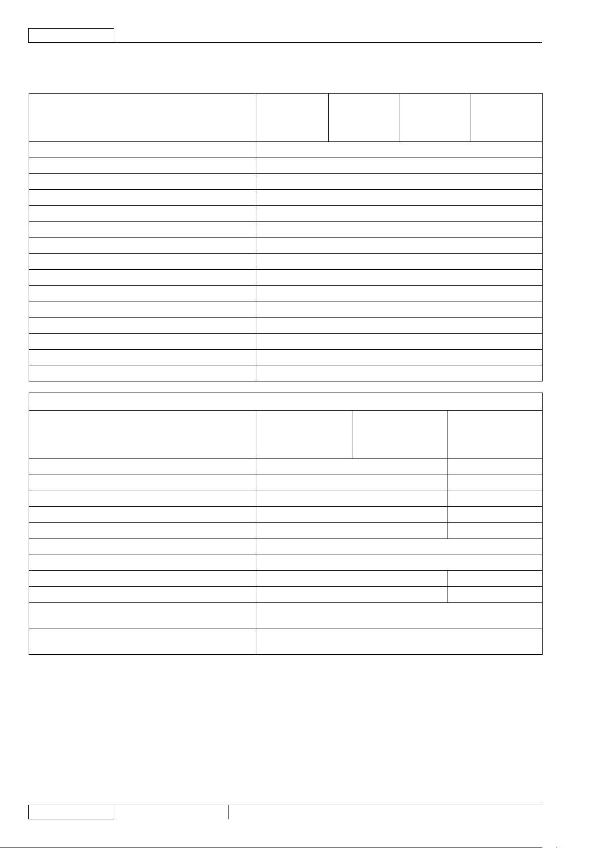
TECHNICAL DATA (For AdnityTM 17 ST - 20 ST)
SERVICE MANUAL
ENGLISH
GENERAL INFORMATION
Model
Machine height 41.6 in (1,058.5 mm)
Solution/clean water tank capacity 10.5 gal (40 litres)
Recovery water tank capacity 10.5 gal (40 litres)
Front wheel diameter 7.8 in (200 mm)
Front wheel specic pressure on the ground * 174 lbf/in2 (1.2 N/mm2)
Rear wheel specic pressure on the ground * 435 lbf/in2 (3 N/mm2)
Rear wheel diameter 3.9 in (100 mm)
Vacuum system motor power 0.44 hp (330 W)
Gradeability 2%
Sound pressure level at workstation 65.8 dB(A)
Standard batteries WET (2 x 12V) 24V 105 Ah
Battery compartment size (width x length x height) 13.8 x 13.8 x 11.8 in (350 x 350 x 300 mm)
Vacuum system circuit capacity 41.5 in H2O (1,055 mm H2O)
Cleaning width 18.0 in (450 mm) 21.0 in (530 mm)
Squeegee width 30.0 in (760 mm)
AdnityTM 17 ST
(1 brush/pad-holder)
AdnityTM 20 ST
(1 brush/pad-holder)
Machine maximum length 46.8 in (1,190 mm) 48.3 in (1,228 mm)
Machine width without squeegee 20.1 in (512 mm) 21.2 in (540.8 mm)
Brush diameter 18.0 in (450 mm) 21.0 in (530 mm)
Weight without batteries and with empty tanks 194.0 lb (88 kg)
Maximum weight with batteries and full tanks 479.6 lb (218 kg)
Brush motor power 0.65 hp (480 W)
Brush speed 153 rpm
Brush/pad-holder pressure 42.0 lb (19.0 kg) 45.1 lb (20.5 kg)
(*) Machine set-up:
max size battery
•
max size brush deck / squeegee
•
solution tank full
•
optionals installed
•
weight veried on each wheel
•
print area veried on concrete for each wheel
•
result expressed as max. value for front and max value for rear wheels
•
AdnityTM 17 ST, 20 ST, 20 D, X 20 D, X 20 C, X 24 D 9096982000(1)2007-02
7
ENGLISH
SERVICE MANUAL
8
9096982000(1)2007-02 AdnityTM 17 ST, 20 ST, 20 D, X 20 D, X 20 C, X 24 D
GENERAL INFORMATION
TECHNICAL DATA (For AdnityTM 20 D - X 20 D - X 20 C - X 24 D)
Model
AdnityTM
20 D
(1 brush/pad-
holder)
AdnityTM
X 20 D
(1 brush/pad-
holder)
AdnityTM
X 20 C
(2 cylindrical
brushes)
Machine height 42.8 in (1,088 mm)
Solution/clean water tank capacity 15.3 gal (58 litres)
Recovery water tank capacity 16.0 gal (60 litres)
Front wheel diameter 9.8 in (250 mm)
Front wheel specic pressure on the ground * 174 lbf/in2 (1.2 N/mm2)
Rear wheel specic pressure on the ground * 667 lbf/in2 (4.6 N/mm2)
Rear wheel diameter 3.9 in (100 mm)
Vacuum system motor power 0.44 hp (330 W)
Drive system motor power 0.27 hp (200 W)
Drive speed (variable) 0 to 3.5 MPH (0 to 5.6 km/h)
Gradeability 2%
Sound pressure level at workstation 65.8 dB(A)
Standard batteries WET (2 x 12V) 24V 130 Ah
Battery compartment size (width x length x height) 13.8 x 13.8 x 11.8 in (350 x 350 x 300 mm)
Vacuum system circuit capacity 41.5 in H2O (1,055 mm H2O)
AdnityTM
X 24 D
(2 brushes/pad-
holders)
Technical data for machines with brush/pad-holder deck
Model
AdnityTM
20 D
(1 brush/pad-holder)
AdnityTM
X 20 D
(1 brush/pad-holder)
AdnityTM
X 24 D
(2 brushes/pad-
holders)
Cleaning width 21.0 in (530 mm) 24.0 in (610 mm)
Squeegee width 30.0 in (760 mm) 32.0 in (810 mm)
Machine maximum length 52.1 in (1,323 mm) 51.6 in (1,311 mm)
Machine width without squeegee 21.3 in (541 mm) 25.4 in (646 mm)
Brush diameter 21.0 in (530 mm) 12.0 in (305 mm)
Weight without batteries and with empty tanks 225.0 lb (102 kg)
Maximum weight with batteries and full tanks 551.1 lb (250 kg)
Brush motor power 0.64 hp (480 W) 0.47 hp (350 W)
Brush speed 153 rpm 230 rpm
Brush/pad-holder pressure with extra-pressure
function turned off
Brush/pad-holder pressure with extra-pressure
function turned on
45.2 lb (20.5 kg)
61.3 lb (27.8 kg)
(*) Machine set-up:
max size battery
•
max size brush deck / squeegee
•
solution tank full
•
optionals installed
•
weight veried on each wheel
•
print area veried on concrete for each wheel
•
result expressed as max. value for front and max value for rear wheels
•
SERVICE MANUAL
GENERAL INFORMATION
Technical data for machines with cylindrical brush deck
AdnityTM
Model
Cleaning width 20.0 in (510 mm)
Squeegee width 30.0 in (760 mm)
Machine maximum length 49.3 in (1,253 mm)
Machine width without squeegee 22.7 in (575.5 mm)
Cylindrical brush size (diameter x length) 4.3 x 20.0 in (110 x 485 mm)
Weight without batteries and with empty tanks 247.0 lb (112 kg)
Maximum weight with batteries and full tanks 573.2 lb (260 kg)
Brush motor power 0.54 hp (400 W)
Cylindrical brush rotation speed 570 rpm
Cylindrical brush pressure 58.4 lb (26.5 kg)
MAINTENANCE
The lifespan of the machine and its maximum operating safety are ensured by correct and regular maintenance
X 20 C
(2 cylindrical brushes)
ENGLISH
WARNING!
Read carefully the instructions in the Safety chapter before performing any maintenance procedure.
The following tables provides the scheduled maintenance. The intervals shown may vary according to particular working
conditions, which are to be dened by the person in charge of the maintenance.
For instructions on maintenance procedures, see the following paragraphs.
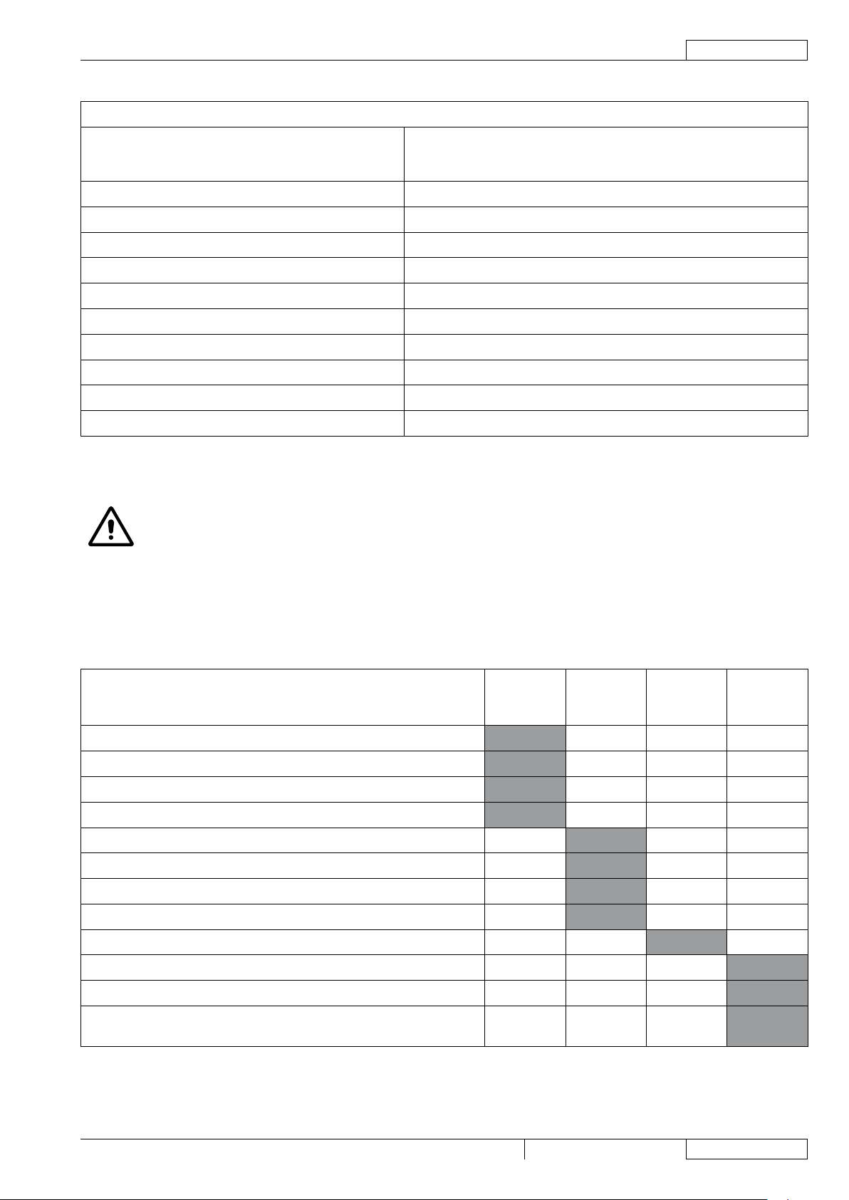
SCHEDULED MAINTENANCE TABLE
Procedure
Battery charging
Squeegee cleaning
Brush/pad cleaning
Tank and vacuum grid with oat cleaning, and cover gasket check
Squeegee blade check and replacement
Solution/clean water lter cleaning
Battery (WET) uid level check
Vacuum system motor lter cleaning
Daily, after
machine
use
Weekly
Every six
months
Yearly
Screw and nut tightening check (1)
Brush/pad-holder motor carbon brush check or replacement
Vacuum system motor carbon brush check or replacement
Drive system motor carbon brush check or replacement
(For AdnityTM 20 D - X 20 D - X 20 C - X 24 D)
(1): And after the rst 8 working hours.
AdnityTM 17 ST, 20 ST, 20 D, X 20 D, X 20 C, X 24 D 9096982000(1)2007-02
9

ENGLISH
SERVICE MANUAL
10
9096982000(1)2007-02 AdnityTM 17 ST, 20 ST, 20 D, X 20 D, X 20 C, X 24 D
GENERAL INFORMATION
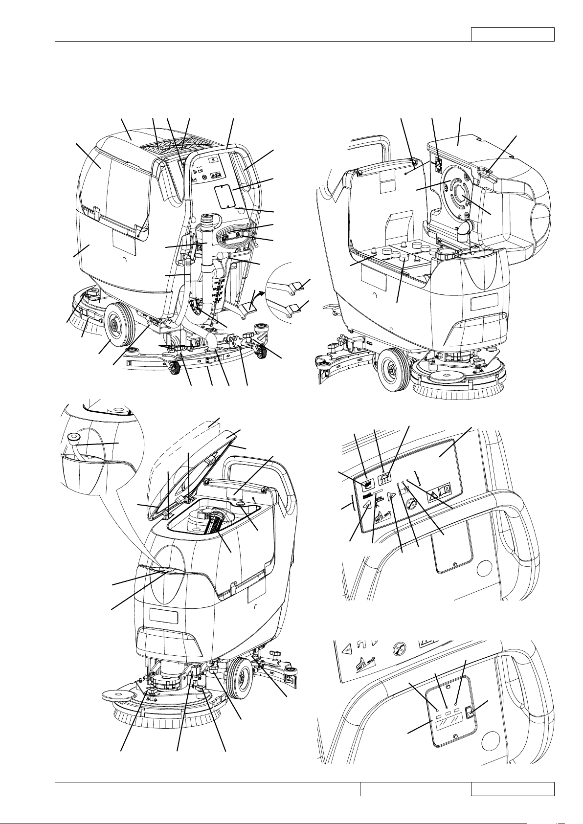
MACHINE NOMENCLATURE (For AnityTM 17 ST - 20 ST)
Throughout this Manual you will nd numbers in brackets – for example: (2). These numbers refer to the components indicated
in these two nomenclature pages. Refer to these pages whenever you need to identify a component mentioned in the text.
Portare la macchina su un pavimento pianeggiante.
Control panel
1.
Handlebar
2.
Battery charger data inspection window
5.
Battery charger cable
6.
Battery charger cable holder
7.
Water removable ller hose (optional)
9.
Squeegee lifting/lowering lever
10.
Deck lifting/lowering pedal
11.
11a. Pedal position when deck is lifted
11b. Pedal position when deck is lowered
Battery connector (red). This connector also works as
12.
EMERGENCY switch, to stop immediately all functions.
Rear steering wheels
13.
Front wheels on xed axle
14.
Squeegee vacuum hose
15.
Recovery water drain hose
16.
Solution/clean water drain and level check hose
17.
Brush/pad-holder deck
18.
Brush/pad-holder with pad
19.
Solution/clean water tank
20.
Recovery water tank
21.
Recovery water tank cover
22.
Can holder
23.
Document retainer (optional)
24.
Squeegee
25.
Squeegee mounting handwheels
26.
Squeegee balance adjusting handwheel
27.
Machine straight forward movement adjusting handwheel
28.
Machine forward speed adjustment handwheel
29.
30a. Recovery water tank cover (opened to be cleaned)
30b. Recovery water tank cover (completely opened)
Tank cover gasket
31.
Cover movable retaining plate
32.
Cover xed retaining plate
33.
Serial number plate/technical data/conformity certication
34.
Plug for squeegee vacuum hose cleaning
35.
Vacuum grid with automatic shut-off oat
36.
Solution ller neck
37.
Foam lter
38.
Compensation hole
39.
Recovery water tank (lifted)
40.
Tank lifting handle
41.
Lifted tank tie rod
42.
Vacuum system motor cover
43.
Vacuum system motor sound-deadening lter
44.
Batteries
52.
Battery caps
53.
Solution lter
54.
Solution/clean water tap
55.
Solenoid valve
56.
Battery connection diagram
58.
Brush/pad-holder and vacuum system switch
71.
Brush/pad-holder and vacuum system switch warning
72.
light
Vacuum system switch
73.
Vacuum system switch warning light
74.
Hour counter (optional)
79.
Battery charge indicator
81.
81a. Charged battery warning light (green)
81b. Semi-discharged battery warning light (yellow)
81c. Discharged battery warning light (red)
Washing water ow control switches
82.
82a. Flow increase switch
82b. Flow decrease switch
82c. Washing water ow indicator
Electronic battery charger
90.
Lead (WET) or gel (GEL) battery selector
91.
Green warning light (ON: the battery charger is on and
92.
batteries are charged)
Yellow warning light (ON: the battery charger is on and
93.
batteries are semi-discharged)
Red warning light (ON: the battery charger is on and it is
94.
charging the batteries)
SERVICE MANUAL
21
22
24
23
1
2
3
4
5
6
7
10
11b
11
12
27
1525
26
13
55
14
19
18
20
16
17
11a
26
42
58
40
41
44
43
52
53
55
51-54
29
56
28
38
37
9
31
32
33
30b
30a
39
34
35
36
79
81a
74
72
71
81b
81c
82a
82b
82c
82
73
81
94
93
92
91
90
GENERAL INFORMATION
MACHINE NOMENCLATURE (For AnityTM 17 ST - 20 ST) (Continues)
ENGLISH
S301514A
AdnityTM 17 ST, 20 ST, 20 D, X 20 D, X 20 C, X 24 D 9096982000(1)2007-02
11

ENGLISH
SERVICE MANUAL
12
9096982000(1)2007-02 AdnityTM 17 ST, 20 ST, 20 D, X 20 D, X 20 C, X 24 D
GENERAL INFORMATION
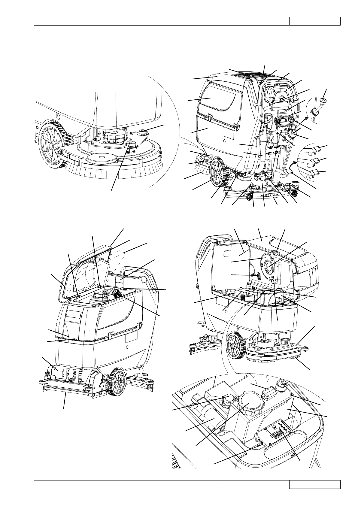
MACHINE NOMENCLATURE (For AnityTM 20 D - X 20 D - X 20 C - X 24 D)
Throughout this Manual you will nd numbers in brackets – for example: (2). These numbers refer to the components indicated
in these two nomenclature pages. Refer to these pages whenever you need to identify a component mentioned in the text.
Control panel
1.
Handlebar
2.
Drive paddle
3.
Speed adjuster
4.
Battery charger data inspection window
5.
Battery charger cable (optional)
6.
Battery charger cable holder (optional)
7.
Solution/clean water rear ller neck
8.
Water removable ller hose (optional)
9.
Squeegee lifting/lowering lever
10.
Deck lifting/lowering pedal
11.
11a. Pedal position when deck is lifted
11b. Pedal position when deck is lowered
11c. Pedal position when the extra pressure function is on
(if applicable)
Battery connector (red). This connector also works as
12.
EMERGENCY switch, to stop immediately all functions.
Rear steering wheel
13.
Front wheels on xed axle
14.
Squeegee vacuum hose
15.
Recovery water drain hose
16.
Solution/clean water drain and level check hose
17.
18a. Deck with one brush/pad-holder
18b. Deck with two brushes/pad-holders
18c. Deck with two cylindrical brushes
19a. Brush/pad-holder with pad
19b. Cylindrical brushes
Solution/clean water tank
20.
Recovery water tank
21.
Recovery water tank cover
22.
Can holder
23.
Document retainer (optional)
24.
Squeegee
25.
Squeegee mounting handwheels
26.
Squeegee balance adjusting handwheel
27.
Machine straight forward movement adjusting handwheel
28.
Machine forward speed adjustment handwheel
29.
30a. Recovery water tank cover (opened to be cleaned)
30b. Recovery water tank cover (completely opened)
Tank cover gasket
31.
Cover movable retaining plate
32.
Cover xed retaining plate
33.
Serial number plate/technical data/conformity certication
34.
Plug for squeegee vacuum hose cleaning
35.
Vacuum grid with automatic shut-off oat
36.
Solution front ller neck
37.
Foam lter
38.
Compensation hole
39.
Recovery water tank (open)
40.
Tank lifting handle
41.
Lifted tank tie rod
42.
Vacuum system motor cover
43.
Vacuum system motor sound-deadening lter
44.
Detergent tank (*)
45.
Detergent tank ller plug (*)
46.
Detergent tank handle (*)
47.
Detergent feed hose (*)
48.
Detergent pump (*)
49.
Water pump (*)
50.
Clean water lter (*)
51.
Batteries
52.
Battery caps
53.
Solution lter
54.
Solution/clean water tap
55.
Solenoid valve
56.
Reference table for detergent proportioning (*)
57.
Battery connection diagram
58.
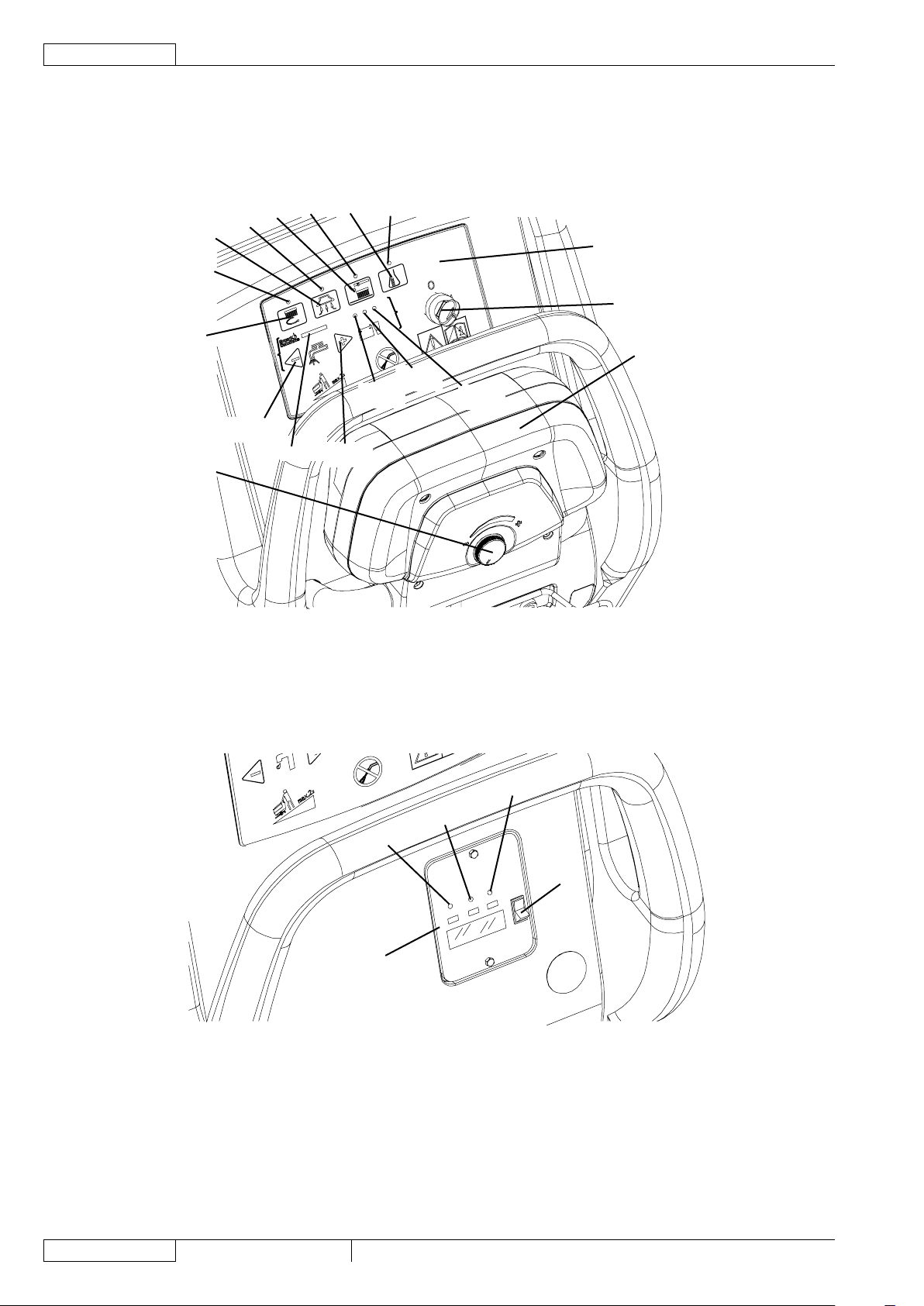
Brush/pad-holder and vacuum system switch
71.
Brush/pad-holder and vacuum system switch warning
72.
light
Vacuum system switch
73.
Vacuum system switch warning light
74.
Brush/pad-holder release switch
75.
Brush/pad-holder release switch warning light
76.
Detergent ow control switch (*)
77.
Detergent ow control switch warning light (*)
78.
Hour counter (optional)
79.
Ignition key (0 - I)
80.
Battery charge indicator
81.
81a. Charged battery warning light (green)
81b. Semi-discharged battery warning light (yellow)
81c. Discharged battery warning light (red)
Washing water ow control switches
82.
82a. Flow increase switch
82b. Flow decrease switch
82c. Washing water ow indicator
Forward/reverse gear paddle
83.
Forward/reverse speed adjuster
84.
Electronic battery charger
90.
Lead (WET) or gel (GEL) battery selector
91.
Green warning light (ON: the battery charger is on and
92.
batteries are charged)
Yellow warning light (ON: the battery charger is on and
93.
batteries are semi-discharged)
Red warning light (ON: the battery charger is on and it is
94.
charging the batteries)
(*) Only for machines equipped with AXP
SERVICE MANUAL
29
28
21
20
56
18a
19a
14
22
24
23
1
2
3
4
5
6
7
8
10
9
11c
11b
11a
11
16
17
54
55
13
26
15
12
25
27
26
19b
18c
39
30b
38
37
35
36
34
31
32
33
30a
46
53
52
18b
19a
47
58
43
42
40 41
48
44
45
47
46
50
51
49
57
48
45
GENERAL INFORMATION
MACHINE NOMENCLATURE (For AnityTM 20 D - X 20 D - X 20 C - X 24 D) (Continues)
ENGLISH
S301516A
AdnityTM 17 ST, 20 ST, 20 D, X 20 D, X 20 C, X 24 D 9096982000(1)2007-02
13
ENGLISH
SERVICE MANUAL
14
9096982000(1)2007-02 AdnityTM 17 ST, 20 ST, 20 D, X 20 D, X 20 C, X 24 D
79
80
83
81a
81b
81
84
82a
81c
82c
82b
71
72
73
74
75
76 77
78
82
94
90
93
92
91
GENERAL INFORMATION
MACHINE NOMENCLATURE (For AnityTM 20 D - X 20 D - X 20 C - X 24 D) (Continues)
S301517A
SERVICE MANUAL
E
G
F
E
D
A
C
B
ENGLISH
SOLUTION/CLEAN WATER SUPPLY SYSTEM
SOLUTION/CLEAN WATER TANK AND SUPPLY SYSTEM CLEANING
Drive the machine to the appointed solution disposal area.
1.
• (For AdnityTM 20 D - X 20 D - X 20 C - X 24 D) Turn the ignition key (80) to “0”.
2.
(For AdnityTM 17 ST - 20 ST) Turn off the switches (71) and (73).
•
Empty the solution/clean water tank (20) with the hose (17).
3.
Start the machine (as shown in the User Manual) and keep it running until the solution/clean water tank is completely
4.
empty.
• (For AdnityTM 20 D - X 20 D - X 20 C - X 24 D) Turn the ignition key (80) to “0”.
5.
(For AdnityTM 17 ST - 20 ST) Turn off the switches (71) and (73).
•
Clean the tank (20) with clean water.
6.
Start the machine (as shown in the User Manual) and keep it running until the solution/clean water tank is completely
7.
empty.
Clean the solution lter (see the following procedure).
8.
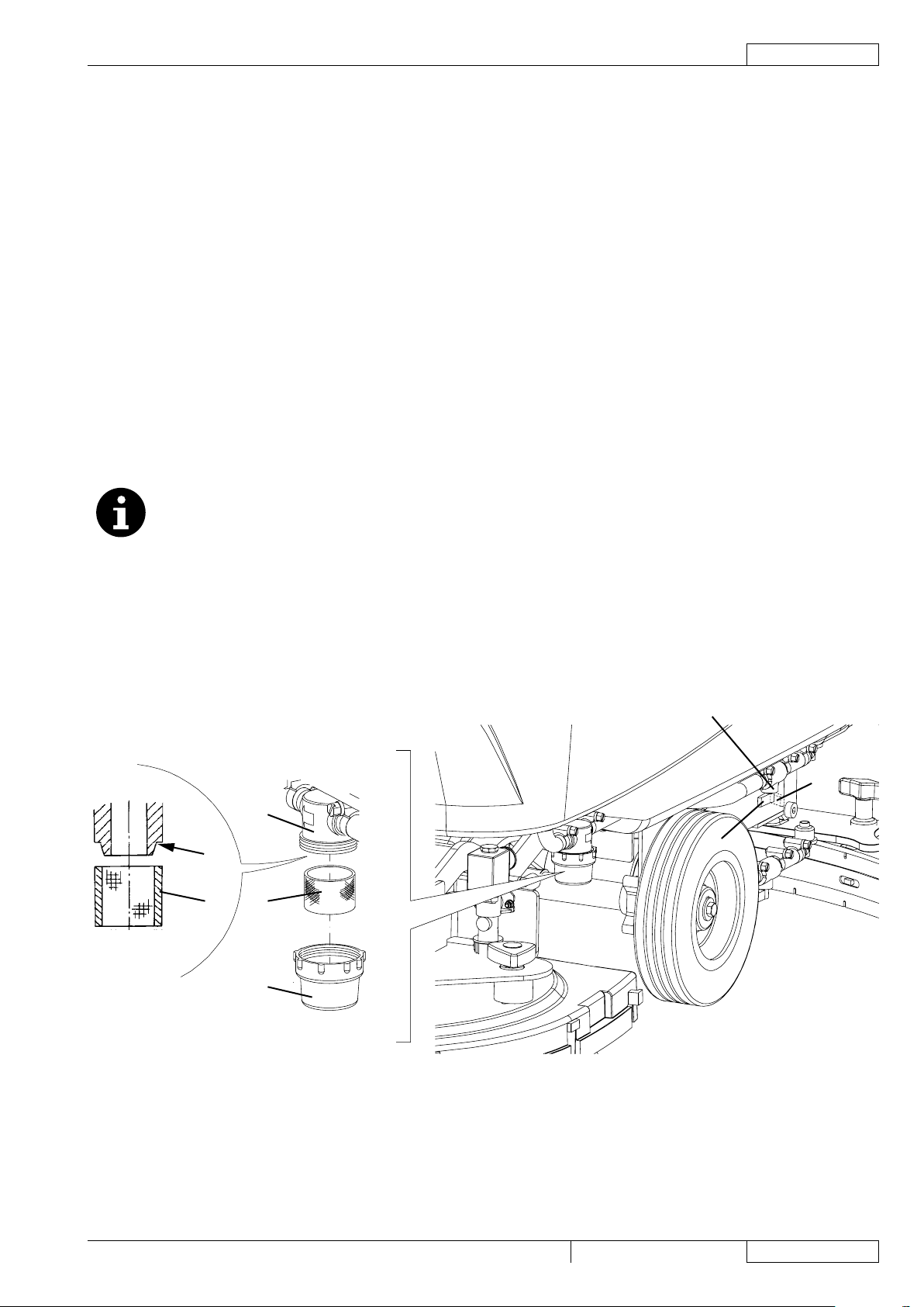
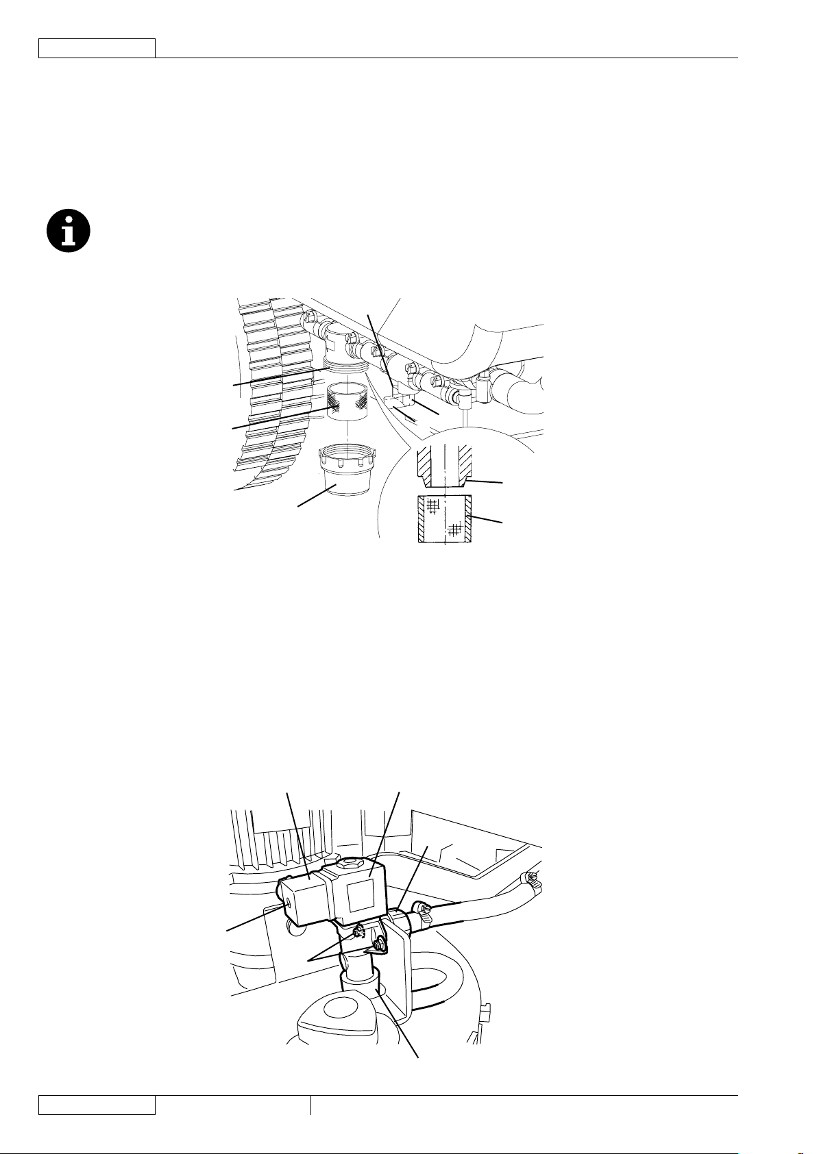
SOLUTION FILTER CLEANING (For AdnityTM 17 ST - 20 ST)
Drive the machine on a level oor.
1.
Turn off the switches (71) and (73).
2.
Close the solution tap (A) under the machine left lower side. The tap (A) is closed when it is on the position (B) and it is
3.
open when it is on the position (C).
Remove the transparent cover (D), then remove the lter strainer (E). Clean and install them on the support (F).
4.
NOTE
The lter strainer (E) must be correctly positioned on the housing (G) of the support (F).
Open the tap (A).
5.
AdnityTM 17 ST, 20 ST, 20 D, X 20 D, X 20 C, X 24 D 9096982000(1)2007-02
S301520A
15
ENGLISH
SERVICE MANUAL
16
9096982000(1)2007-02 AdnityTM 17 ST, 20 ST, 20 D, X 20 D, X 20 C, X 24 D
SOLUTION/CLEAN WATER SUPPLY SYSTEM
E
G
B
A
D
C
F
E
F
E
A
B
D
C
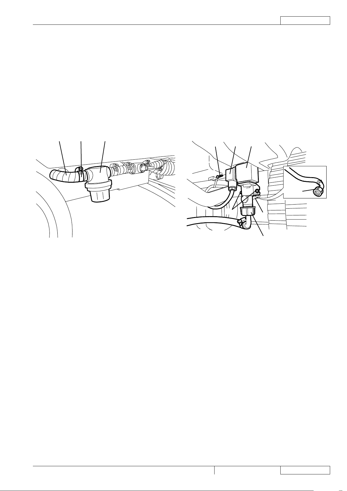
SOLUTION FILTER CLEANING (For AdnityTM 20 D)
Drive the machine on a level oor.
1.
Turn the ignition key (80) to “0”.
2.
Close the solution tap (A) under the machine left lower side. The tap (A) is closed when it is on the position (B) and it is
3.
open when it is on the position (C).
Remove the transparent cover (D), then remove the lter strainer (E). Clean and install them on the support (F).
4.
NOTE
The lter strainer (E) must be correctly positioned on the housing (G) of the support (F).
Open the tap (A).
5.
SOLENOID VALVE DISASSEMBLY/ASSEMBLY (For AdnityTM 17 ST - 20 ST)
Disassembly
Remove the brush.
1.
Lower the deck by pressing the pedal (11).
2.
Remove the screw (A), disconnect the connector (B) and recover the gasket.
3.
Disconnect the union (C) from the solenoid valve (D) and recover the gasket.
4.
Remove the screws (E).
5.
Slightly lift the solenoid valve (D), disconnect the union (F) and recover the gasket.
6.
Recover the solenoid valve (D).
7.
Assembly
Assemble the components in the reverse order of disassembly.
8.
S301521A
S301522A
SERVICE MANUAL
B A C
F
G E
H
I
D
I
ENGLISH
SOLUTION/CLEAN WATER SUPPLY SYSTEM
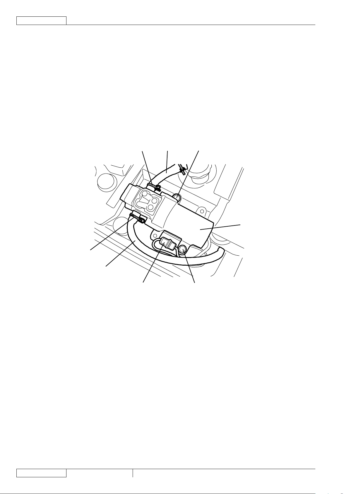
SOLENOID VALVE DISASSEMBLY/ASSEMBLY (For AdnityTM 20 D - X 20 D - X 20 C - X 24 D)
Disassembly
(For machines with brushes/pad-holders) Remove the brushes/pad-holders.
1.
Lower the deck by pressing the pedal (11).
2.
(For AdnityTM 20 D) Loosen the clamp (A) and disconnect the hoses (B) from the lter assembly (C).
3.
Disconnect the union (D) from the solenoid valve (E) and recover the gasket.
4.
Remove the screw (F), disconnect the connector (G) and recover the gasket.
5.
Remove the nuts (H).
6.
• (For AdnityTM 20 D) Remove the solenoid valve (E) with the hoses (B). If necessary, separate the hoses (B) from the
7.
solenoid valve.
(For AdnityTM X 20 D - X 20 C - X 24 D) Move the solenoid valve (E) and disconnect it from the union (I).
•
Assembly
Assemble the components in the reverse order of disassembly.).
8.
TROUBLESHOOTING
SMALL AMOUNT OF SOLUTION OR NO SOLUTION REACHES THE BRUSH
Possible causes
The solution/clean water lter is clogged/dirty (clean).
1.
The solution/clean water tap is stuck closed (replace).
2.
The solenoid valve is broken or there is an open in the electrical connection (replace the solenoid valve/repair the electrical
3.
connection).
There is debris in the solution tank clogging the output hole (clean the tank).
4.
There are debris in the solution/clean water hoses clogging the ow (clean the hoses).
5.
THE SOLUTION/CLEAN WATER REACHES THE BRUSH ALSO WHEN THE MACHINE IS OFF
Possible causes
There is dirt or calcium deposit on the solenoid valve gasket (clean).
1.
The solenoid valve is broken (replace).
2.
S301523A
AdnityTM 17 ST, 20 ST, 20 D, X 20 D, X 20 C, X 24 D 9096982000(1)2007-02
17
ENGLISH
SERVICE MANUAL
18
9096982000(1)2007-02 AdnityTM 17 ST, 20 ST, 20 D, X 20 D, X 20 C, X 24 D
AXP
F
B
C
D
F
A
E
C
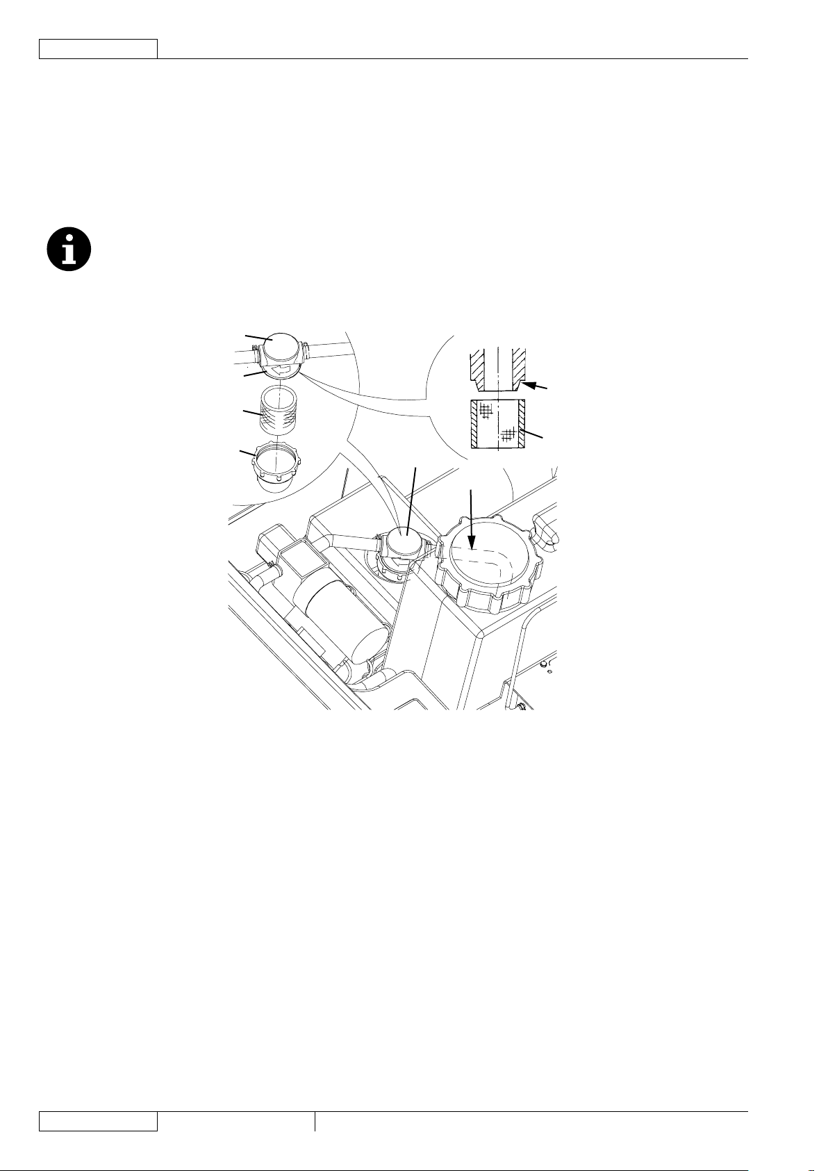
CLEAN WATER FILTER CLEANING (For AdnityTM X 20 D - X 20 C - X 24 D)
Drive the machine on a level oor.
1.
Turn the ignition key (80) to “0”.
2.
Open the cover (22) and check that the recovery water tank (21) is empty, otherwise empty it with the drain hose (16).
3.
Grasp the handle (41) and carefully lift the tank (40).
4.
Slightly lift the hoses (A), then, operating on the clean water lter assembly (F), unscrew the transparent cover (B) and
5.
remove the lter strainer (C). Clean and install them on the support (D).
NOTE
The lter strainer (C) must be correctly positioned on the housing (E) of the support (D).
Install the hoses (A) and the lter assembly (F).
6.
S301524A
SERVICE MANUAL
A
F
C
D
B
E
ENGLISH
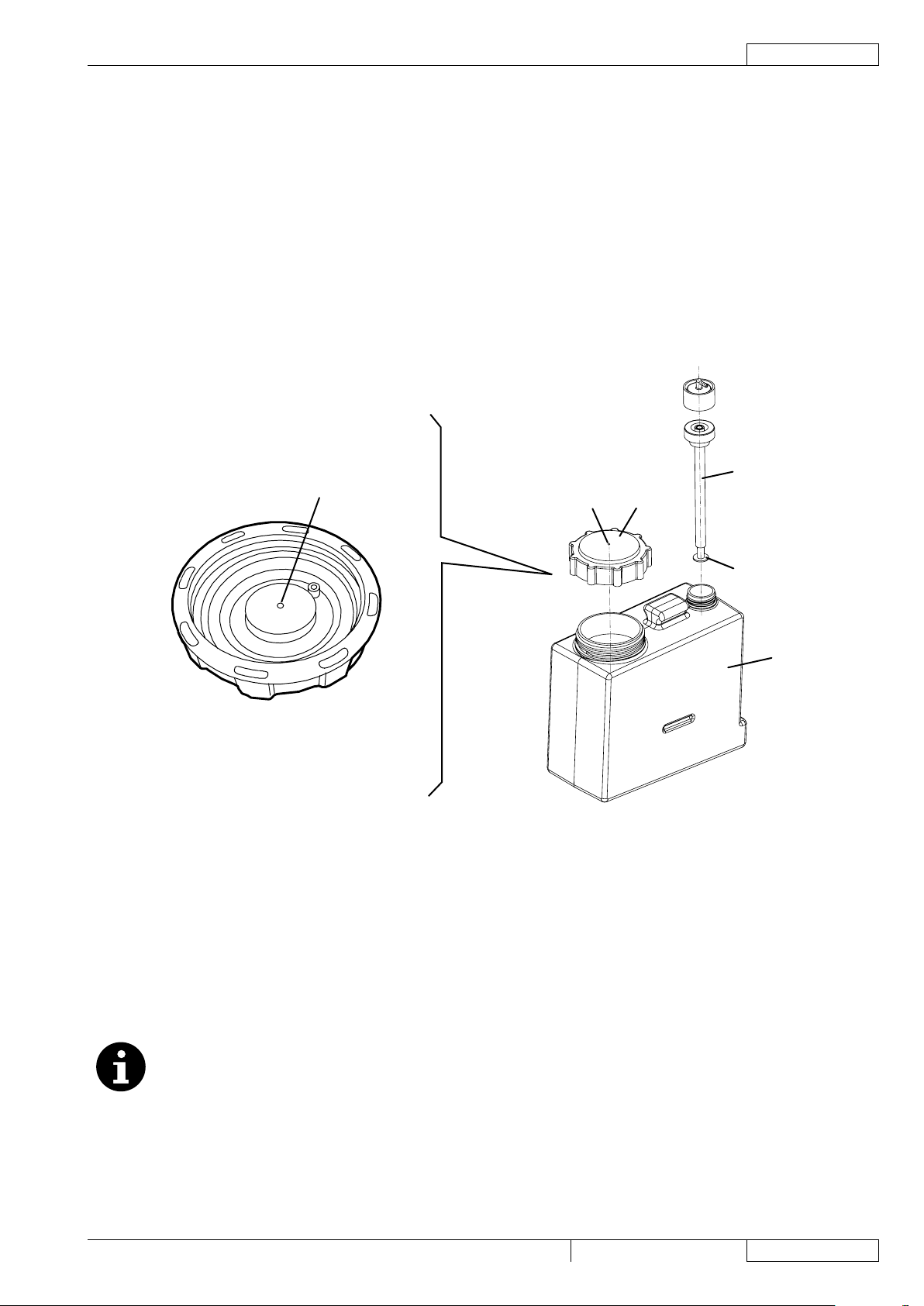
DETERGENT TANK CLEANING (For AdnityTM X 20 D - X 20 C - X 24 D)
Drive the machine to the appointed detergent disposal area.
1.
Turn the ignition key (80) to “0”.
2.
Open the cover (22) and check that the recovery water tank (21) is empty, otherwise empty it with the drain hose (16).
3.
Close the cover (22).
Grasp the handle (41) and carefully lift the tank (40).
4.
Unscrew the union and remove the hose (48) from the tank (45).
5.
Remove the tank (45) by releasing it from the fasteners.
6.
Unscrew the plug (A) and wash the detergent tank (B) in the appointed detergent disposal area. If necessary, remove the
7.
supply hose (C) and clean it, especially in area of the vacuum end pipe (D). Install the supply hose (C).
Check that the plug vent hole (E) is not clogged, by driving in air and checking if it comes out from the outer hole (F). If
8.
necessary clean the hole with compressed air. Install the plug (A).
Install the tank (45) and connect it to the hose (48).
9.
When the detergent tank and the supply hose have been drained, the AXP must be drained too (see the procedure in the
10.
following paragraph).
AXP
AXP DRAINING (For AdnityTM X 20 D - X 20 C - X 24 D)
Clean the detergent tank, then remove the detergent remained in the hoses and in the pump.
1.
Grasp the handle (41) and carefully lower the tank (40).
2.
Turn on the machine by turning the ignition key (80) to “I”.
3.
Turn on the AXP by pressing the switch (77). Check that the switch warning light (78) turns on.
4.
Press the switches (77) and (82a) at the same time, until the switch warning light (78) starts ashing (after about 5
5.
seconds).
Release the switches and wait for the warning light (78) to stop ashing and for the vacuum system to turn on.
6.
Collect the detergent remained on the oor.
7.
Turn the ignition key (80) to “0”.
8.
9.
10.
Grasp the handle (41) and carefully lift the tank (40), then check that the hose (48) is empty, otherwise perform steps 3 to 9
again.
NOTE
The draining cycle lasts about 30 seconds, then the vacuum function automatically turns on, which allows to
remove the detergent remained.
The draining cycle can also be performed with the detergent tank (45) full of water, thus cleaning the system
thoroughly.
It is advisable to perform the draining cycle when the AXP is really dirty/encrusted because the machine has
not been used/cleaned for a long time.
The draining cycle can be performed also to quickly ll the detergent supply hose when the tank (45) is full
but the system is still empty.
If necessary, the draining cycle can be repeatedly performed.
S301525A
AdnityTM 17 ST, 20 ST, 20 D, X 20 D, X 20 C, X 24 D 9096982000(1)2007-02
19
ENGLISH
SERVICE MANUAL
20
9096982000(1)2007-02 AdnityTM 17 ST, 20 ST, 20 D, X 20 D, X 20 C, X 24 D
AXP
B
C
E
D
E
A
C
B
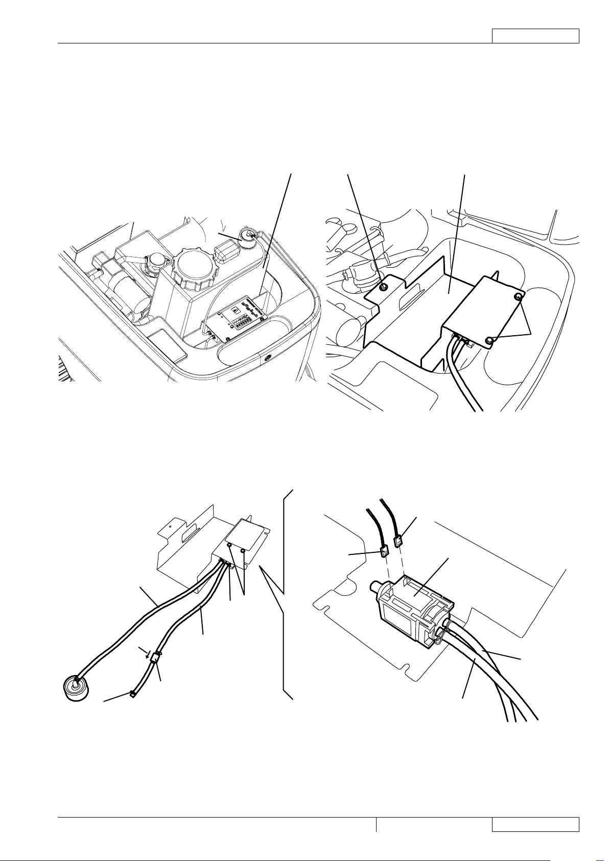
WATER PUMP DISASSEMBLY/ASSEMBLY (For AdnityTM X 20 D - X 20 C - X 24 D)
Disassembly
If the tank (21) contains recovery water:
1.
Drive the machine to the appointed recovery water disposal area.
•
Turn the ignition key (80) to “0”.
•
Empty the recovery water tank (21) with the hose (16).
•
Drive the machine on a level oor.
2.
Turn the ignition key (80) to “0”.
3.
Grasp the handle (41) and carefully lift the tank (40).
4.
Disconnect the connector (A).
5.
Loosen the clamps (B) and disconnect the hoses (C) from the water pump (D).
6.
Remove the screws (E).
7.
Remove the water pump (D).
8.
Assembly
Assemble the components in the reverse order of disassembly.
9.
DETERGENT PUMP AND CHECK VALVE DISASSEMBLY/ASSEMBLY (For AdnityTM X 20 D - X 20
C - X 24 D)
Disassembly
If the tank (21) contains recovery water:
2.
Drive the machine to the appointed recovery water disposal area.
•
Turn the ignition key (80) to “0”.
•
Empty the recovery water tank (21) with the hose (16).
•
Drive the machine on a level oor.
2.
Turn the ignition key (80) to “0”.
3.
Grasp the handle (41) and carefully lift the tank (40).
4.
Unscrew the union (A).
5.
Remove the detergent tank (B).
6.
Remove the screws (C).
7.
Slightly lift the tank holder (D) and mark the position of the connectors (E) and (F) (to reinstall them correctly), which must
8.
be as follows:
Connector (E): white cable
•
Connector (F): blue cable
•
Disconnect the connectors (E) and (F) from the detergent pump (G).
9.
Disconnect the hoses (H) from the relevant union.
10.
Remove the screws (I) and recover the detergent pump (G) together with the hoses.
11.
If necessary, disconnect the hoses (J) and (K) from the pump.
12.
If necessary, mark the position of the arrow (M) (to reinstall the components correctly), which must be as shown in the
13.
gure, and replace the check valve (L).
Assembly
Assemble the components in the reverse order of disassembly.
14.
S301526A
SERVICE MANUAL
A
B
C
C
D
H
M
L
J
K
G
I
F
E
G
K
J
ENGLISH
AXP
DETERGENT PUMP AND CHECK VALVE DISASSEMBLY/ASSEMBLY (For AdnityTM X 20 D - X 20
C - X 24 D) (Continues)
S301528A
AdnityTM 17 ST, 20 ST, 20 D, X 20 D, X 20 C, X 24 D 9096982000(1)2007-02
21
 Loading...