

Advance acoustic 56110001, 56110005, 56110003, 56110004, 56110009 Instructions For Use Manual
...
Condor XL
INSTRUCTIONS FOR USE / INSTRUCCIONES DE USO
Advance Models:
56110000(LPG/48”), 56110001(Petrol/48”), 56110002(Diesel/48”), 56110003(LPG/60”), 56110004(Petrol/60”), 56110005(Diesel/60”)
56110006(LPG/62”), 56110007(Petrol/62”), 56110008(Diesel/62”), 56110009(LPG/67”), 56110010(Petrol/67”), 56110015(Diesel/67”)
56111035(LPG-AXP/48”), 56111036(Petrol-AXP/48”), 56111037(Diesel-AXP/48”)
56111038(LPG-AXP/60”), 56111039(Petrol-AXP/60”), 56111040(Diesel-AXP/60”)
56111041(LPG-AXP/62”), 56111042(Petrol-AXP/62”), 56111043(Diesel-AXP/62”)
56111044(LPG-AXP/67”), 56111045(Petrol-AXP/67”), 56111046(Diesel-AXP/67”)
A-English
B-Español
3/09 revised 4/09 Form No. 56041705

A-2 / ENGLISH
TABLE OF CONTENTS
PAGE
Introduction ........................................................................................... A-3
Cautions and Warnings ........................................................................ A-4
Consignes de prudence et de sécurité .................................................A-5
Know Your Machine .....................................................................A-6 – A-9
Prepare the Machine for Use
General Information ............................................................................A-10
Pre-operational Checklist ........................................................A-11 – A-12
Hydraulic Oil ..................................................................................... A-11
Engine Oil ......................................................................................... A-11
Engine Coolant ................................................................................. A-12
Engine Air Filter ................................................................................ A-12
Fuel ...................................................................................................A-12
Install the Brushes .............................................................................. A-13
Filling the Solution Tank ...................................................................... A-14
Operating the Machine
Starting the Engine ............................................................................. A-15
Detergent (AXP) System .........................................................A-16 – A-17
Scrubbing ................................................................................A-18 – A-19
Wet Vacuuming .................................................................................. A-18
After Using the Machine
After Use .............................................................................................A-20
Shutting Down the Engine .................................................................. A-20
Maintenance
Maintenance Schedule ....................................................................... A-20
Lubricating the Machine ..........................................................A-20 – A-21
Side Broom Maintenance ................................................................... A-22
Squeegee Maintenance ......................................................................A-23
Squeegee Adjustment ........................................................................ A-23
Side Skirt Maintenance .......................................................................A-24
Debris Hopper Maintenance ............................................................... A-25
Troubleshooting .......................................................................A-26 – A-27
Technical Specifi cations .....................................................................A-28
A-2 - FORM NO. 56041705 - Condor XL™

ENGLISH / A-3
INTRODUCTION
This manual will help you get the most from your Advance Rider Scrubber. Read it thoroughly before operating the machine.
Note: Bold numbers in parentheses indicate an item illustrated on pages 6 – 9.
PARTS AND SERVICE
Repairs, when required, should be performed by your Authorized Advance Service Center, who employs factory trained service personnel, and maintains an
inventory of Advance original replacement parts and accessories.
Call the ADVANCE DEALER named below for repair parts or service. Please specify the Model and Serial Number when discussing your machine.
(Dealer, affi x service sticker here.)
NAME PLATE
The Model Number and Serial Number of your machine are shown on the Nameplate on the machine. This information is needed when ordering repair parts for
the machine. Use the space below to note the Model Number and Serial Number of your machine for future reference.
MODEL NUMBER _______________________________________________________
SERIAL NUMBER ______________________________________________________
UN-CRATING
Upon delivery, carefully inspect the shipping crate and the machine for damage. If damage is evident, save all parts of the shipping crate so that they can be
inspected by the trucking company that delivered the machine. Contact the trucking company immediately to fi le a freight damage claim.
1 After removing the crate, remove the wooden blocks next to the wheels.
2 Check the engine oil and coolant levels.
3 Check the hydraulic oil level.
4 Read the instructions in the Preparing the Machine For Use section of this manual, then fi ll the fuel tank.
6 Place a ramp next to the front end of the pallet.
7 Read the instructions in the Operating Controls and Operating the Machine sections of this manual and start the engine. Slowly drive the machine forward
down the ramp to the fl oor. Keep your foot lightly on the brake pedal until the machine is off the pallet.
CAUTION!
Use extreme CAUTION when operating this machine. Be certain that you are thoroughly familiar with all operating instructions before
using this machine. If you have any questions, contact your supervisor or your local Advance Industrial Dealer.
If the machine malfunctions, do not try to correct the problem unless your supervisor directs you to do so. Have a qualifi ed company
mechanic or an authorized Advance Dealer service person make any necessary corrections to the equipment.
Use extreme care when working on this machine. Loose clothing, long hair, and jewelry can get caught in moving parts. Turn the Key
Ignition Switch OFF and remove the key before servicing the machine. Use good common sense, practice good safety habits and
pay attention to the yellow decals on this machine.
Drive the machine slowly on inclines. Use the Brake Pedal (23) to control machine speed while descending inclines. DO NOT turn
the machine on an incline; drive straight up or down.
The maximum rated incline for sweeping and scrubbing is 10.5%(6°). The maximum rated incline during transport is 16%(9°).
FORM NO. 56041705 - Condor XL™ - A-3
A-4 / ENGLISH
CAUTIONS AND WARNINGS
SYMBOLS
Advance uses the symbols below to signal potentially dangerous conditions. Always read this information carefully and take the
necessary steps to protect personnel and property.
DANGER!
Is used to warn of immediate hazards that will cause severe personal injury or death.
WARNING!
Is used to call attention to a situation that could cause severe personal injury.
CAUTION!
Is used to call attention to a situation that could cause minor personal injury or damage to the machine or other property.
Read all instructions before using.
GENERAL SAFETY INSTRUCTIONS
Specifi c Cautions and Warnings are included to warn you of potential danger of machine damage or bodily harm.
DANGER!
* This machine emits exhaust gases (carbon monoxide) that can cause serious injury or death, always provide adequate
ventilation when using machine.
WARNING!
* This machine shall be used only by properly trained and authorized persons.
* While on ramps or inclines, avoid sudden stops when loaded. Avoid abrupt sharp turns. Use low speed down hills. Clean only
while ascending (driving up) the ramp.
* To avoid hydraulic oil injection or injury always wear appropriate clothing and eye protection when working with or near hydraulic
system.
* Turn the key switch (50) off (O) and disconnect the batteries before servicing electrical components.
* Never work under a machine without safety blocks or stands to support the machine.
* Do not dispense fl ammable cleaning agents, operate the machine on or near these agents, or operate in areas where fl ammable
liquids exist.
* Do not clean this machine with a pressure washer.
CAUTION!
* This machine is not approved for use on public paths or roads.
* This machine is not suitable for picking up hazardous dust.
* Use care when using scarifi er discs and grinding stones. Advance will not be held responsible for any damage to fl oor surfaces
caused by scarifi ers or grinding stones.
* When operating this machine, ensure that third parties, particularly children, are not endangered.
* Before performing any service function, carefully read all instructions pertaining to that function.
* Do not leave the machine unattended without fi rst turning the key switch (50) off (O), removing the key and applying the parking
brake.
* Turn the key switch (50) off (O) before changing the brushes, and before opening any access panels.
* Take precautions to prevent hair, jewelry, or loose clothing from becoming caught in moving parts.
* Use caution when moving this machine in below freezing temperature conditions. Any water in the solution or recovery tanks or
in the hose lines could freeze.
* Before use, all doors and hoods should be properly latched.
SAVE THESE INSTRUCTIONS
A-4 - FORM NO. 56041705 - Condor XL™
ENGLISH / A-5
CONSIGNES DE PRUDENCE ET DE SECURITE
SYMBOLES
Advance utilise les symboles reproduits ci-dessous pour attirer l’attention de l’opérateur sur des situations potentiellement dangereuses. Il est donc conseillé de
lire attentivement ces indications et de prendre les mesures adéquates en vue de protéger le personnel et le matériel.
DANGER !
Ce symbole est utilisé pour mettre l’opérateur en garde contre les risques immédiats pouvant provoquer des dommages corporels graves, voire entraîner la mort.
ATTENTION !
Ce symbole est utilisé pour attirer l’attention sur une situation susceptible d’entraîner des dommages corporels graves.
PRUDENCE !
Ce symbole est utilisé pour attirer l’attention de l’opérateur sur une situation qui pourrait entraîner des dommages corporels minimes ou des dommages à la
machine ou à d’autres équipements.
Lire toutes les instructions avant d’utiliser l’appareil.
CONSIGNES GENERALES DE SECURITE
Les consignes spécifi ques de prudence et de sécurité mentionnées ici ont pour but de vous informer de la survenance de tout risque de dommages matériels ou
corporels.
DANGER !
* Les gaz d’échappement (monoxyde de carbone) évacués par la machine peuvent entraîner de graves dommages corporels, voire la mort. Veillez donc
toujours à bénéfi cier d’une ventilation suffi sante lorsque vous utilisez la machine.
ATTENTION !
* Cette machine ne pourra être utilisée que par du personnel parfaitement entraîné et dûment autorisé.
* Evitez les arrêts subits lorsque la machine est chargée et se trouve sur des rampes ou des plans inclinés. Evitez les virages serrés. Adoptez une vitesse
réduite lorsque la machine est en descente. Ne nettoyez que lorsque la machine monte la pente.
* Lorsque vous utilisez le système hydraulique ou travaillez à proximité de celui-ci, veillez à porter une tenue appropriée et des lunettes de protection afi n
d’éviter tout risque de blessures ou toute projection d’huile.
* Positionnez la clé de contact sur (50) off (O) et déconnectez les batteries avant de procéder à l’entretien des composants électriques.
* Ne travaillez jamais sous une machine sans y avoir placé, au préalable, des blocs de sécurité ou des étais destinés à soutenir la machine
* Ne déversez pas d’agents nettoyants infl ammables, ne faites pas fonctionner la machine à proximité de ces agents ou d’autres liquides infl ammables.
* Ne nettoyez pas cette machine avec un nettoyeur à pression.
PRUDENCE !
* Cette machine n’est pas conçue pour une utilisation sur les chemins ou voies publiques.
* Cette machine n’est pas conçue pour le ramassage des poussières dangereuses.
* Faites extrêmement attention lorsque vous utilisez des disques de scarifi cateur et des meules. Advance ne pourra, en aucun cas, être tenu pour responsable
des dommages occasionnés à vos sols par ce type d’équipement.
* Lors de l’utilisation de cette machine, assurez-vous que des tiers, et notamment des enfants, ne courent pas le moindre risque.
* Avant de procéder à toute opération d’entretien, veuillez lire attentivement toutes les instructions qui s’y rapportent.
* Ne laissez pas la machine sans surveillance sans avoir, au préalable, coupé le contact, enlevé la clé de contact (O) et tiré le frein à main.
* Positionnez la clé de contact sur (50) off (O) avant de remplacer les brosses ou d’ouvrir tout panneau d’accès.
* Prenez toutes les mesures nécessaires pour éviter que les cheveux, les bijoux ou les vêtements amples ne soient entraînés dans les parties mobiles de la
machine.
* Faites attention lorsque vous déplacez cette machine dans un endroit où la température peut descendre sous 0°. Car l’eau contenue dans la solution, dans
les réservoirs de récupération ou dans les conduites risquerait de geler.
* Avant utilisation, toutes les portes et capots doivent être correctement fermés.
CONSERVEZ SOIGNEUSEMENT CES INSTRUCTIONS
FORM NO. 56041705 - Condor XL™ - A-5
A-6 / ENGLISH
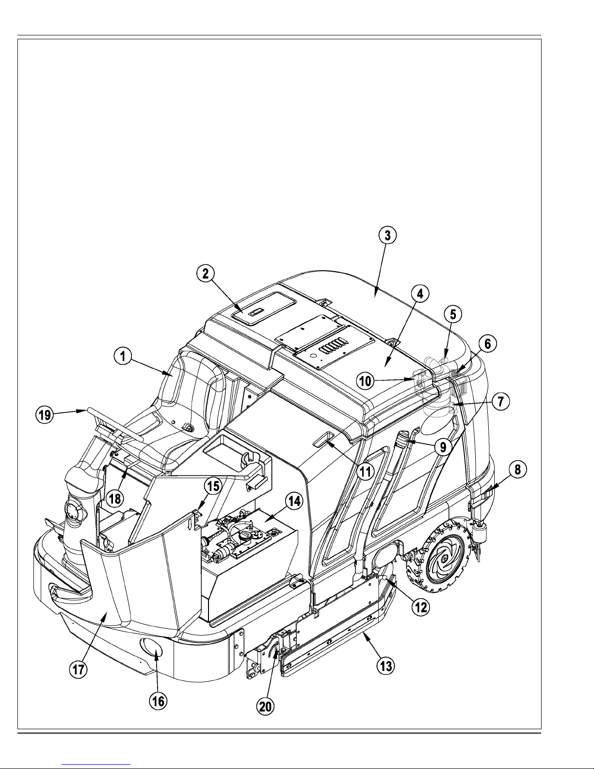
KNOW YOUR MACHINE
As you read this manual, you will occasionally run across a bold number or letter in parentheses - example: (2). These numbers refer to an item shown on these
pages unless otherwise noted. Refer back to these pages whenever necessary to pinpoint the location of an item mentioned in the text.
1 Operator’s Seat
2 Solution Tank Fill Cover
3 Engine Cover
4 Recovery Tank Cover
5 Engine Air Filter Service Indicator
6 Coolant Overfl ow Tank
7 Engine Air Filter
8 Engine Cover Latch
9 Recovery Tank Drain Hose
10 Recovery Tank Tilt Out Latch
11 Recovery Tank Tilt Out Grip
12 Left Side Skirt Latch
13 Left Side Skirt
14 Fuel Tank (petrol tank shown)
15 Fuel Tank Cover Latch
16 Head Light
17 Fuel Tank Cover
18 Operator Seat Adjustment Lever
19 Steering Wheel
20 Double Scrub Skirt Holder
A-6 - FORM NO. 56041705 - Condor XL™
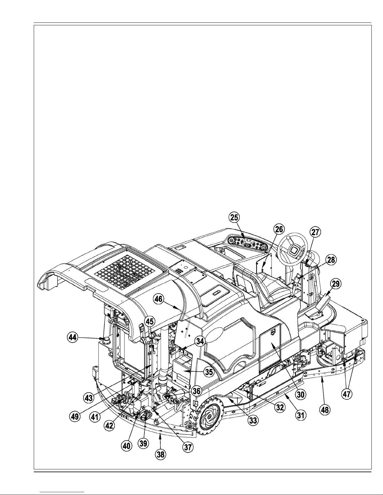
KNOW YOUR MACHINE
25 Control Panel
26 Circuit Breaker Panel (see Troubleshooting)
27 Steering Wheel Tilt Adjust Lever
28 Brake Pedal / Parking Brake
29 Drive Pedal, Directional/Speed
30 AXP Cartridge Compartment
31 Right Side Skirt
32 Right Side Skirt Latch
33 Hopper
34 Tow Valve Lever
35 Battery
36 Solution Filter
37 Solution Tank Drain Hose
38 Squeegee Assembly
39 Squeegee Height Adjust Knob
40 Squeegee Mount Wrench
ENGLISH / A-7
41 Squeegee Tilt Adjust Knob
42 Engine Oil Filter
43 Engine Cover Prop Rod
44 Hydraulic Oil Reservoir Filler Cap
45 Oil Cooler Tilt Out Latch
46 Engine Oil Dipstick
47 Right Scrub Skirt Retainer Knobs
48 Right Scrub Skirt Assembly
49 Engine Oil Drain (under radiator)
FORM NO. 56041705 - Condor XL™ - A-7
A-8 / ENGLISH
KNOW YOUR MACHINE
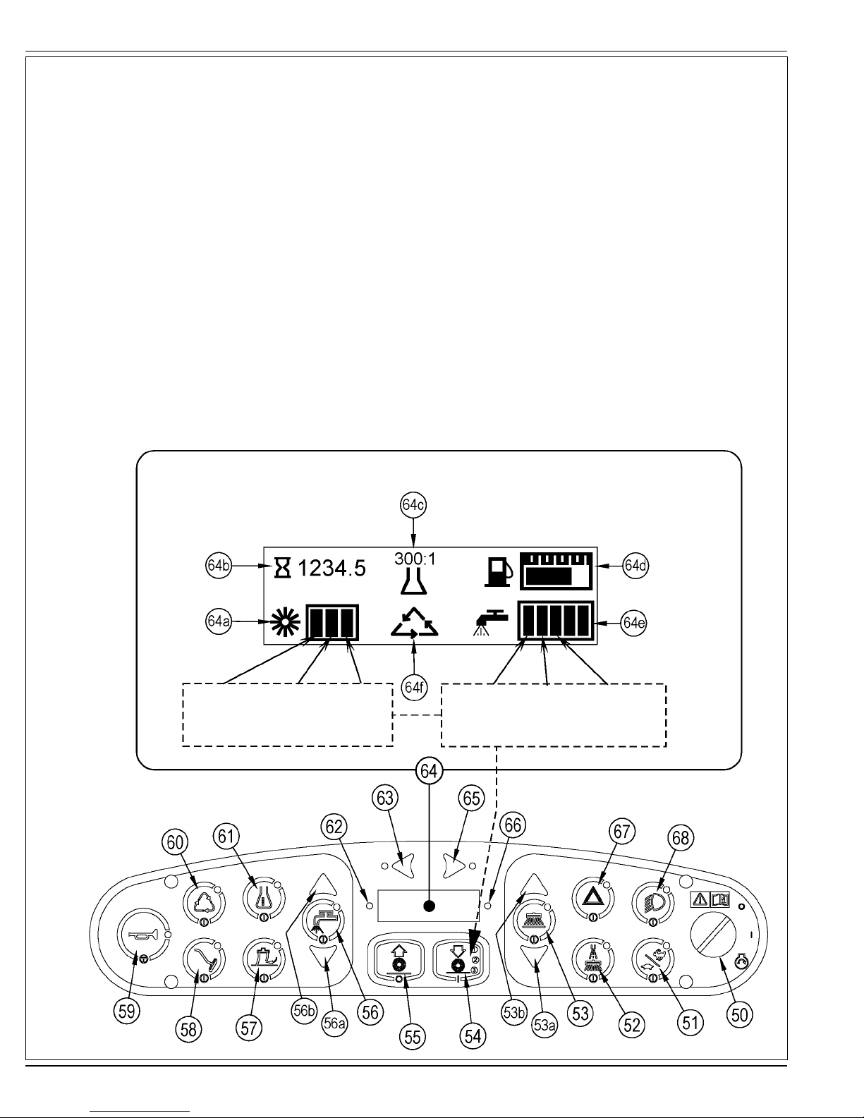
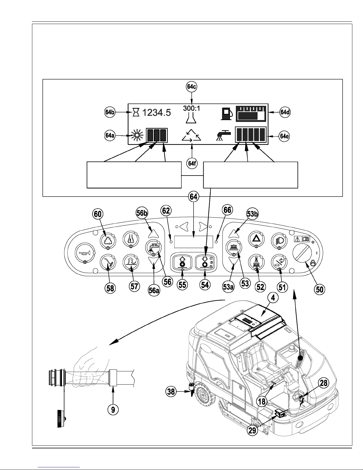
50 Key Switch
51 Engine Speed Switch
52 Dust Guard
53 Side Broom/Scrub ON / OFF Switch
53a Side Broom DOWN adjust Switch
53b Side Broom UP adjust Switch
54 Scrub ON / Scrub Mode Select
55 Scrub OFF
56 Solution Switch
56a Solution Flow Decrease Switch
56b Solution Flow Increase Switch
57 Vacuum Switch
58 Wand Switch (optional / see next page)
59 Horn Switch
60 Extended Scrub Switch (optional / see next page)
61 Detergent System (AXP models only)
62 Warning Indicator Light (RED)
62a Parking Brake ON
62b Oil Pressure (Diesel)
62c Engine Service
62d Battery Low
62e Controller Fault
62f Hydraulic Temp
62g Low Fuel
62h Engine Temp
63 Left Turn Signal (optional)
64 Display
64a Scrub Pressure Indicator
64b Hour Meter
64c AXP Indicator (optional)
64d Fuel Gauge
64e Solution Flow Indicator
64f Extended Scrub Indicator (optional)
65 Right Turn Signal (optional)
66 Attention Indicator Light (YELLOW)
66a Solution Low
66b Hydraulic Filter Plugged
66c Non Critical Fault / Non Critical Engine Service
66d Glow Plug
66e Recovery Tank FULL
67 Emergency Flashers (optional)
68 Head Lights
(scrub 1) (scrub 2) (scrub 3)
press 1 time press 2 times press 3 times
A-8 - FORM NO. 56041705 - Condor XL™
Flow Flow Flow
Rate 1 Rate 2 Rate 3
(scrub 1) (scrub 2) (scrub 3)
press 1 time press 2 times press 3 times
revised 4/09
ENGLISH / A-9
KNOW YOUR MACHINE
WAND SWITCH (58)
See Vac Wand Kit Instruction Sheet form number 56040944.
EXTENDED SCRUB SWITCH (60)
See Extended Scrub Kit Instruction Sheet form number 56040945.
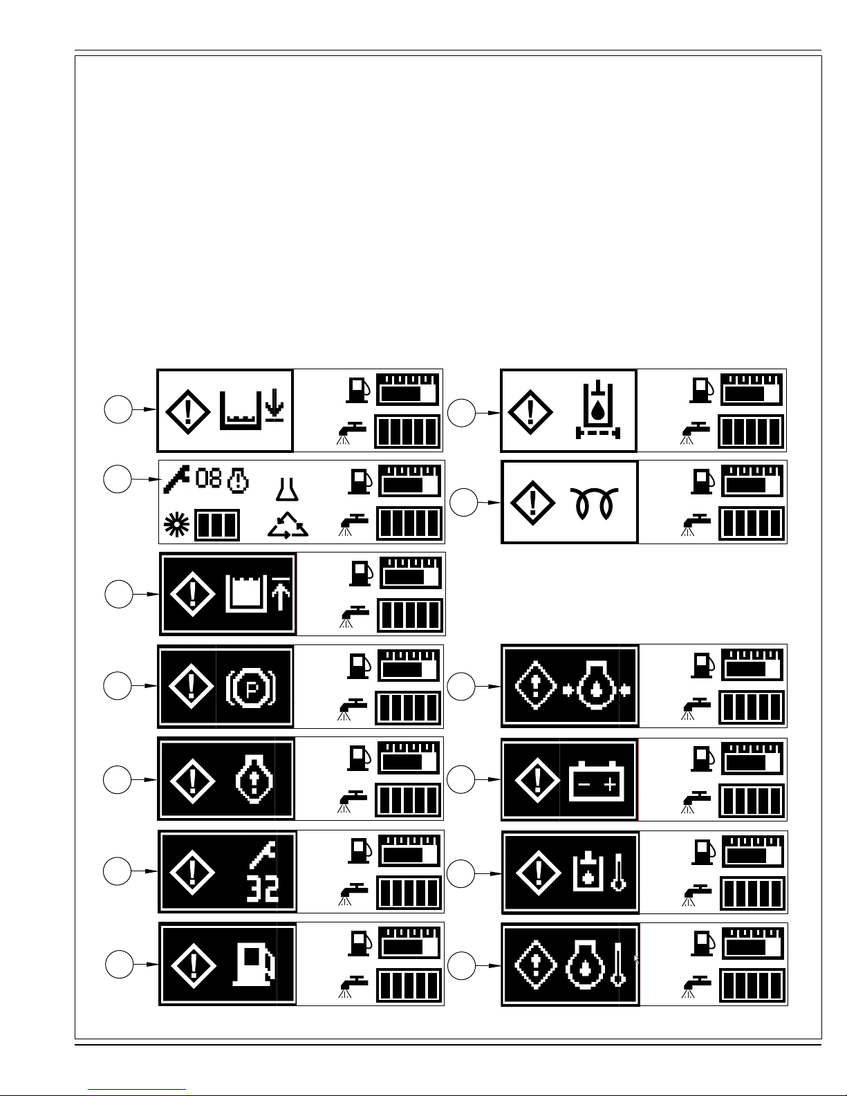
IF ANY OF THE WARNING / ATTENTION ICONS MARKED (X) BELOW ARE DISPLAYED PLEASE CONTACT YOUR ADVANCE
AUTHORIZED SERVICE CENTER.
66a
66c
X
66e
62a
62c
66b
X
300:1
66d
62b
X
62d
X
62e
X
62g
revised 4/09
X
62f
X
62h
X
FORM NO. 56041705 - Condor XL™ - A-9
A-10 / ENGLISH
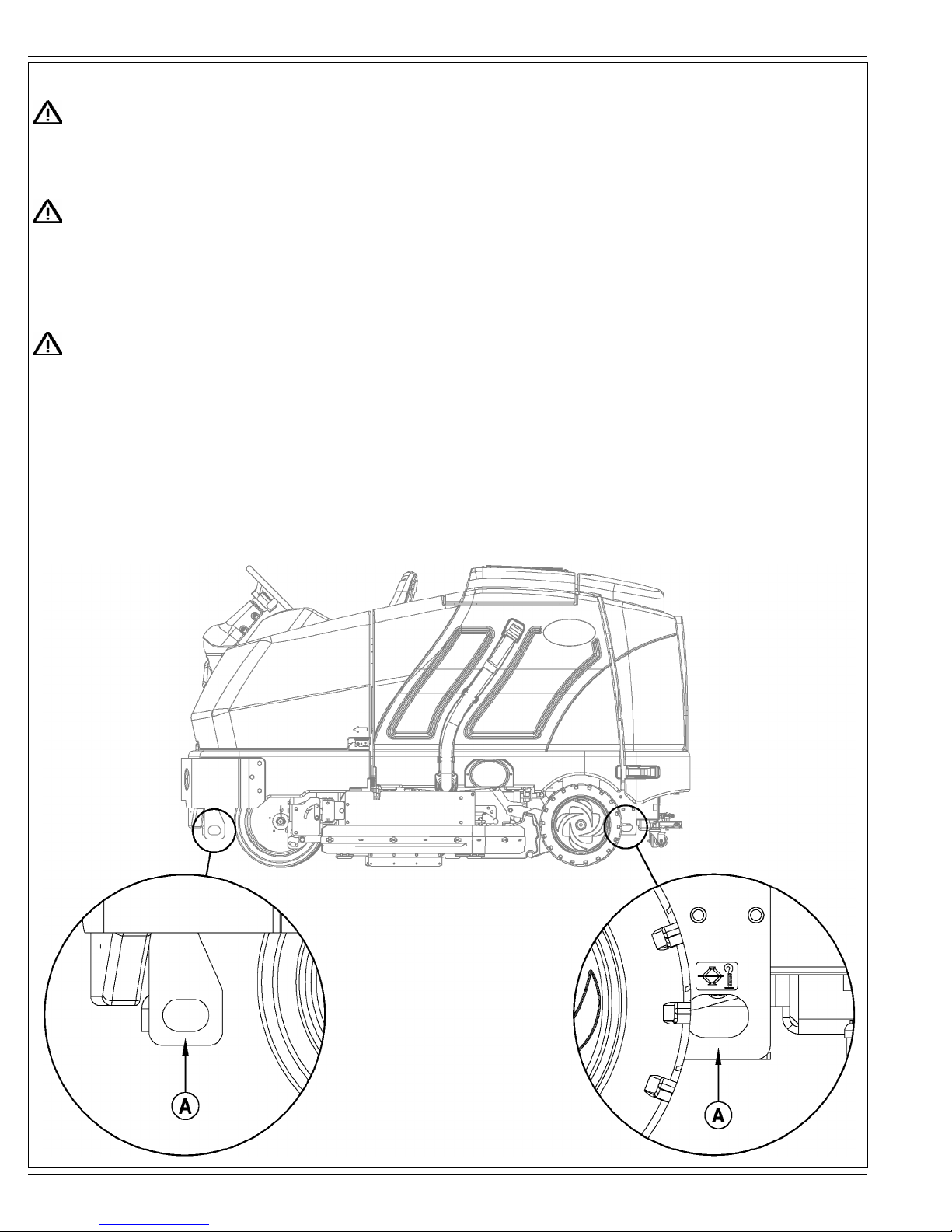
JACKING THE MACHINE
CAUTION!
Never work under a machine without safety stands or blocks to support the machine.
• When jacking the machine, do so at designated locations - see Tie Down / Jacking Locations (A) in Figure 1.
TRANSPORTING THE MACHINE
CAUTION!
Before transporting the machine on an open truck or trailer, make sure that . . .
• All access doors are latched securely.
• The machine is tied down securely - see Tie Down / Jacking Locations (A) in Figure 1.
• The machine Parking Brake (28) is set.
TOWING OR PUSHING A DISABLED MACHINE
CAUTION!
The machine’s drive propelling pump is manufactured with an adjustable tow valve. This valve prevents damage to the hydraulic
system when the machine is being towed/pushed short distances without use of the engine.
The tow valve is controlled by the Tow Valve Lever (34) which is accessed by opening and propping the Engine Cover (3). Pull The Tow Valve Lever (34) out; this
disengages the hydrostatic lock between the motor and pump.
The hydrostatic pump can be damaged if the machine is towed with the valve in the normal working position (Tow Valve Lever (34) pushed IN). Note: If the tow
valve is left in free wheeling position (Tow Valve Lever (34) pulled OUT) the hydrostatic pump can’t drive the machine FWD or REV. No damage will result, just
reset the valve to the normal working position by pushing the lever IN. Tow or push the machine no faster than a normal walking pace (2-3 miles per hour) and for
short distances only. If the machine is to be moved long distances the front drive wheel needs to be raised off the fl oor and placed on a suitable transport dolly.
FIGURE 1
A-10 - FORM NO. 56041705 - Condor XL™

ENGLISH / A-11
PRE-OPERATIONAL CHECKLIST
Before Each Use:
* Inspect the machine for damage, oil or coolant leaks.
* Squeeze the rubber dust cup on the Engine Air Filter (7) to release built-up dust.
* Check the engine coolant level (6).
* Check the engine oil level (46).
* Check the hydraulic oil level (44).
* Check the Fuel Gauge (64d) on the gasoline/petrol, and diesel models.
* Check the Fuel Gauge located on the LP tank for LPG model.
* Check the Air Filter Service Indicator (5).
In the Driver’s Seat:
* Be sure that you understand the operating controls and their functions.
* Adjust the seat to allow easy reach of all controls.
* Insert the Master Key and turn the Ignition Key Switch (50) to the ON position. Check for proper operation of the Horn (59), Hour Meter (64b) and Headlights
(68). Turn the Ignition Key Switch (50) OFF.
* Check the Brake Pedal (28). The pedal should be fi rm and should not go all the way down. The latch should hold the pedal when applied.
(Report all defects immediately to service personnel).
Plan Your Cleaning in Advance:
* Arrange long runs with a minimum of stopping or starting.
* Allow 2-3” (5.08-7.62cm) of scrub path overlap to ensure complete coverage.
* Avoid making sharp turns, bumping into posts, or scraping the side of the machine.
HYDRAULIC OIL
Open and prop the Engine Cover (3) to access the hydraulic oil reservoir. Remove the Fill Cap (44) from the tank and look to the bottom of the fi ller screen. If
the oil level is below the bottom of the fi ller screen, add 10W30 motor oil until the bottom of the fi ller screen is covered (oil level should not be higher than 1/2”
(12.7mm) above the bottom of the fi ller screen). Change the oil if major contamination from a mechanical failure occurs.
ENGINE OIL – GASOLINE / PETROL & LPG
Check the engine oil level when the machine is parked on a level surface and the engine is cool. Change the engine oil after the fi rst 35 hours of
operation and every 150 hours after that. Use any SF or SG rated oil meeting API specifi cations and suited to seasonal temperatures. Refer to
the Engine System section for oil capacities and additional engine specifi cations. Replace the oil fi lter with every oil change.
TEMPERATURE RANGE OIL WEIGHT
Above 60° F (15° C) SAE 10W-30
Below 60° F (15° C) SAE 5W-30
ENGINE OIL - DIESEL
Check the engine oil level when the machine is parked on a level surface and the engine is cool. Change the engine oil after the fi rst 35 hours
of operation and every 150 hours after that. Use CF, CF-4 or CG-4 oil meeting API specifi cations and suited temperatures (*important reference
the oil/fuel type note below for further diesel oil recommendations). Refer to the Engine System section for oil capacities and additional engine
specifi cations. Replace the oil fi lter with every oil change.
TEMPERATURE RANGE OIL WEIGHT
Above 77 °F (25 °C) SAE 30 or 10W-30
32 °F to 77 °F (0 °C to 25 °C) SAE 20 or 10W-30
Below 32 °F (0 °C) SAE 10W or 10W-30
* Diesel Lubricating Oil Note:
With the emission control now in effect, the CF-4 and CG-4 lubricating oils have been developed for use with a low-sulfur fuel used in on-road vehicle
engines. When an off-road vehicle engine runs on a high-sulfur fuel, it is advisable to employ the CF, CD or CE lubricating oil with a high total base number.
If the CF-4 or CG-4 lubricating oil is used with a high-sulfur fuel, change the lubricating oil at shorter intervals.
• Lubricating oil recommended when a low-sulfur or high-sulfur fuel is employed.
Fuel
Lubricating
Oil class
CF
CF-4
CG-4
O : Recommended X : Not recommended
Low sulfur
(0.5 % ≥)
OO
OX
OX
High sulfur Remarks
TBN ≥ 10
FORM NO. 56041705 - Condor XL™ - A-11

A-12 / ENGLISH
PRE-OPERATIONAL CHECKLIST
ENGINE COOLANT
CAUTION!
Do not remove the radiator cap when the engine is hot.
To check the engine coolant level, open and prop the Engine Cover (3) and observe the coolant level on the Coolant Recovery Tank (6). If the level is low add
automotive type anti-freeze appropriately diluted for the environment. Clean the radiator and oil cooler exteriors by washing with low-pressure water or using
compressed air every 30 hours. Service Note: The oil cooler tips out for easy cleaning.
ENGINE AIR FILTER
Check the Air Filter Service Indicator (5) before each use of the machine. Do not service the air fi lter unless the red fl ag is visible in the service indicator.
CAUTION!
When servicing the engine air fi lter elements, use extreme care to prevent loose dust from entering the engine. Dust can severely
damage the engine.
The engine air fi lter contains a Primary (outer) and a Safety (inner) fi lter element. The Primary Element may be cleaned twice before being replaced. The Safety
Element should be replaced every third time that the Primary Filter Element is replaced. Never attempt to clean the Inner Safety Element.
To clean the Primary Filter Element, unsnap the 2 clips at the end of the air fi lter and remove the end housing. Pull the primary element out. Clean the element
with compressed air (maximum pressure 100 psi) or wash it with water (maximum pressure 40 psi). DO NOT put the element back into the canister until it is
completely dry.
FUEL
WARNING!
• ALWAYS STOP THE ENGINE BEFORE FILLING THE FUEL TANK.
• DO NOT SMOKE WHILE FILLING THE FUEL TANK.
• FILL THE FUEL TANK IN A WELL-VENTILATED AREA.
• DO NOT FILL THE FUEL TANK NEAR SPARKS OR OPEN FLAME.
• USE ONLY THE FUEL SPECIFIED ON THE FUEL TANK DECAL.
On machines with diesel and gasoline engines, a decal near the Fuel Tank (14) fi ller neck shows the proper fuel to use in the machine. Before removing the cap
from the tank, wipe all dust and dirt from the cap and from the top of the tank to keep the fuel as clean as possible.
On machines with propane engines, a decal near the tank gives specifi c information about the proper type of tank to be used on the machine.
DIESEL ENGINE
Fill the tank with Number 2 Diesel Fuel if the machine will be used in an area where the temperature is 30° Fahrenheit (0° Celsius) or higher. Use Number 1
Diesel Fuel if the machine will be used in an area where the temperature is below 30° Fahrenheit (0° Celsius).
NOTE: If the diesel machine runs out of fuel completely, the fuel system must be bled before the engine can be re-started. To avoid this situation, fi ll the fuel tank
when the fuel gauge indicates 1/4 tank. Fuel tank capacity is 11 gallons (42 liters).
GASOLINE / PETROL ENGINE
FILL THE TANK WITH UNLEADED 87 OCTANE REGULAR GASOLINE. FUEL TANK CAPACITY IS 11 GALLONS (42 LITERS).
Note: Reference the separately supplied engine manufacture’s maintenance and operator manual for more detailed engine specifi cation and service data.
LPG ENGINE
Mount a standard 33 lb. liquid withdrawal propane tank on the machine, connect the fuel hose and open the shutoff valve on the tank. Wear gloves when
connecting or disconnecting the fuel hose. Shut the propane tank service valve OFF when the machine is not in use.
A-12 - FORM NO. 56041705 - Condor XL™
ENGLISH / A-13
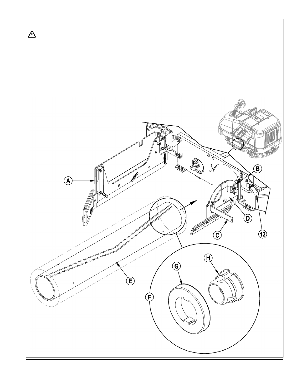
INSTALL THE BRUSHES
CAUTION!
Turn the key switch off (O) and remove the key, before changing the brushes, and before opening any access panels.
1 Make sure the Scrub Deck is in the RAISED position, the Key Switch (50) is off (O) and the Parking Brake (28) is set.
2 See Figure 2. Push down on the Side Skirt Latch (12 or 32) and swing the Skirt Assy (A) open as shown.
3 Lift up on Latch (B), swing Lever (C) out and pull to open the Idler Assembly (D).
4 Slide the Brush (E) into the housing, lift slightly, push and turn until it seats. NOTE: Figure 2 shows a closeup view (F) of the Brush Lugs (G) and the Brush
Drive Hub (H).
5 Swing the Idler Assembly (D) closed while holding Lever (C) at a 90 degree angle to the Idler.
6 Once the Idler Assembly (D) is closed, push Lever (C) in until Latch (B) can be slid back down in front of it.
7 Push down on the Side Skirt Latch (12 or 32), swing the Skirt Assy (A) closed and release the Latch.
NOTE: Refer to this section when rotating (fl ipping end-to-end) brushes according to the maintenance schedule.
FIGURE 2
FORM NO. 56041705 - Condor XL™ - A-13

A-14 / ENGLISH
FILLING THE SOLUTION TANK
See Figure 3. Fill the solution tank with a maximum of 100 gallons (378.54 Liters) of cleaning solution. Do not fi ll the solution tank above 7.5 cm (3 inches) from
the bottom of the Solution Fill (2). The solution should be a mixture of water and the proper cleaning chemical for the job. Always follow the dilution instructions on
the chemical container label. NOTE: AXP machines can either be used conventionally with detergent mixed in the tank or the AXP detergent dispensing system
can be used. When using the AXP detergent dispensing do not mix detergent in the tank, plain water should be used.
CAUTION!
Use only low-foaming, non-fl ammable liquid detergents intended for machine application. Water temperature should not exceed 130
degrees fahrenheit (54.4 degrees celsius)
FIGURE 3
A-14 - FORM NO. 56041705 - Condor XL™

ENGLISH / A-15
OPERATING THE MACHINE
The Condor XL™ is a rider-type automatic fl oor scrubbing machine. It is designed to lay down cleaning solution, scrub the fl oor, and vacuum dry all in one pass.
The controls on the Condor XL were designed with one touch operation in mind. For single pass scrubbing the user can simply depress one switch and all scrub
functions on the machine will be activated.
NOTE: Bold numbers in parentheses indicate an item illustrated on pages 6-9.
NOTE!: MAKE SURE THE FOOT PEDAL IS IN THE NEUTRAL POSITION. THE ENGINE WILL NOT CRANK IF THE FOOT PEDAL IS NOT IN
NEUTRAL.
STARTING THE DIESEL ENGINE
1 Turn the key switch (50) clockwise to the RUN (ON) position. The glow plugs will activate for 10 seconds as indicated by the attention indicator (66) and the
glow plug icon (66d) on the display. If the engine is already warm, turn the key switch to the start position to crank the engine. If the engine is cold, wait for
the attention indicator and glow plug icon to turn off before cranking the engine. The engine should start immediately. If the engine does not start within 15
seconds release the key, wait for approximately one minute and repeat the above steps.
2 Let the engine run at IDLE speed for fi ve minutes before using the machine.
3 Press the Engine Speed Switch (51) once to switch to FULL THROTTLE and move the machine around for two to three minutes at slow speed to warm up
the hydraulic system.
STARTING THE GASOLINE / PETROL ENGINE
1 Turn the Ignition Key Switch (50) clockwise to the START position and release it as soon as the engine starts. If the engine does not start after cranking for
15 seconds, release the key, wait for 1 minute, then try again.
2 Let the engine run at “IDLE” speed for 5 minutes before using the machine.
3 Push the Engine Speed Switch (51) once to switch to “FULL THROTTLE” and move the machine around for 2 or 3 minutes at a slow speed to warm up the
hydraulic system.
STARTING THE LPG ENGINE
1 Open the service valve on the LP fuel tank.
2 Turn the Ignition Key Switch (50) clockwise to the START position and release it as soon as the engine starts. If the engine does not start after cranking for
15 seconds, release the key, wait for 1 minute, then try again.
3 Let the engine run at “IDLE” speed for 5 minutes before using the machine.
4 Push the Engine Speed Switch (51) once to switch to “FULL THROTTLE” and move the machine around for 2 or 3 minutes at a slow speed to warm up the
hydraulic system.
ALWAYS operate the machine with the Engine Speed Switch at full throttle. Use the Drive Pedal (29) not the Engine Speed Switch (51) to control the speed
of the machine. The speed of the machine will increase as the pedal is pushed closer to the fl oor. Do not press the Drive Pedal (29) until the engine has started.
Engine Speed Switch (51):
There are three engine speed settings that can be selected by the engine speed switch (51) on the control panel.
1 “Idle” (1200 RPM – Petrol / LPG) (1300 RPM – Diesel). Use for warm up and cool down. The engine speed switch light will be off.
2 “Run” (2200 RPM). Use for transporting and most scrubbing operations. The engine speed light will be on.
3 “Turbo” (2400 RPM). Use only for heavy engine load situations such as heavy scrubbing on inclines. The engine speed light will be on.
4 To select between Idle and Run press and release the engine speed switch.
5 To select the Turbo speed, fi rst set the speed to Run. Then press and hold the engine speed switch for 2 seconds. To go back to Run speed, press the switch
again.
6 The Condor XL has an automatic idle feature that will reduce the engine speed to idle when the foot pedal (29) has been in the neutral position for 20
seconds or more. The selected engine speed will automatically resume when the foot pedal is moved from neutral. If the engine speed switch (51) is pressed
while in idle-override, the automatic idle feature will be temporarily disabled until the next time the foot pedal is moved from the neutral position. This can be
useful during troubleshooting or if it is desired to let the machine run at full speed for warming up.
FORM NO. 56041705 - Condor XL™ - A-15

A-16 / ENGLISH
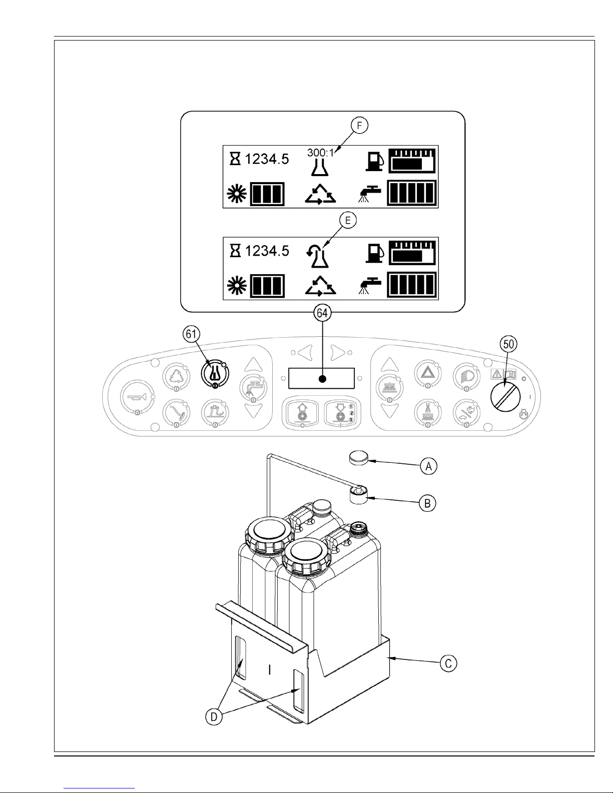
DETERGENT SYSTEM PREPARATION AND USE (AXP MODELS ONLY)
Fill the detergent cartridge with a maximum of 2.2 gallons (8.32 Liters) of detergent. SERVICE NOTE: Remove the detergent cartridge from the detergent box prior to fi lling to avoid
spilling detergent on the machine.
It is recommended that a separate cartridge be used for each detergent you plan to use. The detergent cartridges have a white decal on them so you can write the detergent name on
each cartridge to avoid mixing them up. When installing a new cartridge, remove the Cap (A) and place the cartridge in the detergent box. Install the Dry Break Cap (B) as shown.
The system should be purged of previous detergent when switching to a different detergent. SERVICE NOTE: Move machine over fl oor drain before purging because a small amount
of detergent will be dispensed in the process.
To Purge When Changing Chemicals(SCRUB SYSTEM MUST BE OFF):
1 Disconnect and remove the detergent cartridge.
2 Turn the key switch (50) to the RUN (ON) position. Wait a few seconds for the start-up sequence to fi nish.
3 Press and hold the detergent switch (61) for approximately 2 seconds. Release the switch when the chemical purge icon (E) appears on the display and the indicator on the
detergent switch (61) starts fl ashing. NOTE: Once activated the purge process takes at least 10 seconds. See illustration on next page for Detergent System indicators.
Normally one purge cycle is adequate to purge the system.
To Purge Weekly(SCRUB SYSTEM MUST BE OFF):
1 Disconnect and remove the detergent cartridge. Install and connect a Cartridge fi lled with clean hot water.
2 Turn the key switch (50) to the RUN (ON) position. Wait a few seconds for the start-up sequence to fi nish.
3 Press and hold the detergent switch (61) for approximately 2 seconds. Release the switch when the chemical purge icon (E) appears on the display and the indicator on the
detergent switch (61) starts fl ashing. NOTE: Once activated the purge process takes at least 10 seconds. See illustration on next page for Detergent System indicators.
Normally one purge cycle is adequate to purge the system.
The Detergent Box (C) has Detergent Level Viewing Slots (D) for referencing the amount of detergent remaining in the cartridge(s). When the detergent level is nearing the bottom of
this slot it is time to refi ll or replace the cartridge(s).
Detergent Ratio (SCRUB SYSTEM MUST BE ON):
The detergent mixture rate may be adjusted by pressing and holding the detergent switch (61) for two seconds. Release the switch once the detergent switch light begins fl ashing.
While the light is fl ashing, pressing and releasing the detergent switch will select the next detergent mixture. Once the desired mix is selected the detergent system will return to normal
operation within three seconds.
Once set, the detergent fl ow rate automatically increases and decreases with the solution fl ow rate but the detergent ratio remains the same. If an operator would prefer the fl exibility
of setting different detergent dilutions ratios for different solution fl ow rates this specifi c programming can be found in the service manual. During scrubbing, the detergent system can
be turned off at any time by pressing the Detergent ON/OFF Switch (61) to allow scrubbing with water only. No detergent is dispensed until the scrub system is activated and the Drive
Pedal (29) pushed forward.
SERVICE NOTE: Follow the “To Purge Weekly” instructions above if the machine is going to be stored for an extended period of time or if you
(AXP) system.
The detergent mixture (F) will be displayed for approximately 10 seconds each time the scrub mode changes or each time the detergent switch is pressed.
plan to discontinue use of the detergent
A-16 - FORM NO. 56041705 - Condor XL™
revised 4/09
DETERGENT SYSTEM PREPARATION AND USE (AXP MODELS ONLY)
FIGURE 4
ENGLISH / A-17
FORM NO. 56041705 - Condor XL™ - A-17

A-18 / ENGLISH
SCRUBBING
WARNING!
Be sure you understand the operator controls and their functions.
While on ramps or inclines, avoid sudden stops when loaded. Avoid abrupt sharp turns. Use low speed down hills.
To Scrub...
Follow the instructions in preparing the machine for use section of this manual. Start the engine following the instructions in the appropriate “Starting the …
Engine” section.
1 See Figure 5. While seated on the machine, adjust the seat and steering wheel to a comfortable operating position using the adjustment controls (18 & 27).
2 Release the Parking Brake (28). To transport the machine to the work area, apply even pressure with your foot on the front of the Drive Pedal (29) to go forward or the rear of
the pedal for reverse. Vary the pressure on the foot pedal to obtain the desired speed.
3 Press the Solution Switch (56) and hold for 5 seconds to pre-wet the fl oor. NOTE: This will help prevent scarring of the fl oor surface when starting to scrub with dry brushes.
This must be done prior to pressing the Scrub ON Switch (54).
4 Press the Scrub ON Switch (54) once for Light Scrub (1), twice for Medium Scrub (2) or three times for Heavy Scrub (3) mode. Both the solution fl ow and detergent (AXP
models) fl ow have 3 presets that coincide with the 3 scrub modes (see Display Panel (64)). The right side scrub brush pressure is also affected when pressing this switch.
NOTE: The solution fl ow rate can be overridden simply by pressing the Solution Flow Decrease or Increase Switches (56a / 56b). Any subsequent scrub pressure adjustments
will reset the solution fl ow rate to correspond with the scrub pressure.
NOTE: The scrub, solution, vacuum, detergent (AXP models) and side broom(s) / brush systems are automatically enabled when the Scrub ON Switch (54) is pressed.
Any individual system can be turned OFF or back ON by simply pressing its switch at any time during scrubbing. If you have installed the Extended Scrub Kit, it will not be
automatically activated. You must press the Extended Scrub Switch (60) to activate this system. The Extended Scrub system will not turn ON until the water level in the recovery
tank reaches a certain level and the clean solution has been used up.
5 When the Scrub ON Switch (54) is selected, the brushes, squeegee and side broom(s) / brush are automatically lowered to the fl oor. The scrub, solution, vacuum, detergent
(AXP models) and side broom(s) / brush systems all start when the Drive Pedal (29) is activated.
NOTE: When operating the machine in reverse the squeegee automatically raises and the solution fl ow will stop.
6 Begin scrubbing by driving the machine forward in a straight line at a normal walking speed and overlap each path by 2-3” (5.08-7.62cm). Adjust the machine speed and solution
fl ow when necessary according to the condition of the fl oor.
The side broom height can be adjusted by pressing the Side Broom DOWN and UP Switches (53a/53b). The side broom(s) will return to the last used position each time the
sweep system is turned on. The side brooms have a misting function (Dust Guard) (52) for use in dusty conditions. NOTE: The “Dust Guard” (52) comes on automatically
with the Side Brooms (53) but can be turned OFF by pressing (52). NOTE: If equipped with Extended Scrub, the “Dust Guard” will shut off when the machine runs out of clean
solution.
CAUTION!
To avoid damaging the fl oor, keep the machine moving while the brushes are turning (the brushes will turn OFF after a 2 second delay when the
drive pedal is placed in the neutral position).
Raise scrub deck and side scrub brush, if so equipped, when crossing speed bumps. Do not attempt to operate the scrub deck or side brush in the
down position when crossing speed bumps. Hydraulic pressure pushes down on the brushes and attempting to operate in the scrub mode over a
speed bump can cause damage to the machine.
7 When scrubbing, check behind the machine occasionally to see that all of the waste water is being picked up. If there is water trailing the machine, you may be dispensing too
much solution, the recovery tank may be full, or the squeegee tool may require adjustment.
8 For extremely dirty fl oors, a one-pass scrubbing operation may not be satisfactory and a “double-scrub” operation may be required. This operation is the same as a one-pass
scrubbing except on the fi rst pass the squeegee is in the up position (press the Vacuum Switch (57) to raise the squeegee). This allows the cleaning solution to remain on the
fl oor to work longer. The Side Skirts (13 & 31) can also be raised for double scrubbing if needed with the Skirt Holders (20). The fi nal pass is made over the same area, with the
squeegee and skirts lowered to pick up the accumulated solution.
9 The recovery tank has a fl oat switch that causes ALL systems to turn OFF except the drive system when the recovery tank is full. When this fl oat switch is activated, the
recovery tank must be emptied. The machine will not pick up water or scrub with the fl oat switch activated.
NOTE: The Attention Indicator Light (66) will light up YELLOW and the Recovery Full Icon (66e) will display when the fl oat switch is activated. If the control repeatedly gives a
full indication when the tank is not full check to make sure the fl oat moves freely.
10 When the operator wants to stop scrubbing, press the Scrub OFF Switch (55) once. This will automatically stop the scrub brushes, side broom(s) / brush, solution fl ow and
detergent fl ow. The scrub deck and side broom(s) / brush will raise up. The squeegee will raise up after a brief delay and the vacuum will stop after a brief delay (this is to allow
any remaining water to be picked up without turning the vacuum back on).
11 Drive the machine to a designated waste water “DISPOSAL SITE” and empty the recovery tank. To empty, pull the Drain Hose (9) from its storage area, then remove the plug
(hold the end of the hose above the water level in the tank to avoid sudden, uncontrolled fl ow of waste water). The Recovery Tank Drain Hose (9) can be squeezed to regulate
the fl ow. Refi ll the solution tank and continue scrubbing.
NOTE: Make sure the Recovery Tank Cover (4) and the Recovery Tank Drain Hose (9) cap are properly seated or the machine will not pick-up water correctly.
SERVICE NOTE: Refer to the service manual for optional programmability.
A-18 - FORM NO. 56041705 - Condor XL™
revised 4/09
OPERATING THE MACHINE
FIGURE 5
ENGLISH / A-19
(scrub 1) (scrub 2) (scrub 3)
press 1 time press 2 times press 3 times
Flow Flow Flow
Rate 1 Rate 2 Rate 3
(scrub 1) (scrub 2) (scrub 3)
press 1 time press 2 times press 3 times
FORM NO. 56041705 - Condor XL™ - A-19

A-20 / ENGLISH
AFTER USE
1 When fi nished scrubbing, press the Scrub Off Switch (55). This will automatically raise, retract and stop all the machine systems (brush, squeegee, vacuum, solution and
detergent (AXP models)). Then drive the machine to a service area for daily maintenance and review of other needed service up keep.
2 To empty the solution tank, remove the Solution Drain Hose (37) from it’s storage clamp. Direct the hose to a designated “DISPOSAL SITE” and remove the cap. Rinse the tank
with clean water.
3 To empty the recovery tank, pull the Recovery Tank Drain Hose (9) from its storage area. Direct the hose to a designated “DISPOSAL SITE” and remove the plug (hold the end
of the hose above the water level in the tank to avoid sudden, uncontrolled fl ow of waste water). The Recovery Tank Drain Hose can be squeezed to regulate the fl ow. Rinse
the recovery tank with clean water. Inspect the recovery and vacuum hoses; replace if kinked or damaged.
4 Remove the brushes, remove any string or banding that is wrapped around them, rinse in warm water and stand on end to dry. NOTE: Brushes should be fl ipped “end for end”
and rotated “front to back” daily for longest life.
5 Remove the squeegee, rinse it with warm water and re-install on mount.
6 Remove the Hopper (33) and clean thoroughly. Remove from the right side of the machine by opening the skirt, disconnecting the vacuum hose and then pulling out. NOTE:
Reconnect vacuum hose after re-installing.
7 Check the maintenance schedule and perform any required maintenance before storage
SHUTTING DOWN THE DIESEL / GASOLINE ENGINE
1 Put all controls to the OFF position.
2 Raise the squeegee, the scrub brushes, and the brooms.
3 Push the Engine Speed Switch (51) to change to “Idle” speed and let the engine idle for 30 seconds.
4 Apply the Parking Brake (28).
5 Turn the Key Ignition Switch (50) OFF and remove the key.
SHUTTING DOWN THE LPG ENGINE
1 Put all controls to the OFF position.
2 Raise the squeegee, the scrub brushes, and the brooms.
3 Turn the service valve on LP gas tank OFF.
4 Push the Engine Speed Switch (51) to change to “Idle” speed and let the engine idle until all the LP gas is dispelled from the line.
5 Apply the Parking Brake (28).
6 Turn the Key Ignition Switch (50) OFF and remove the key.
IMPORTANT NOTE: During normal operation the engine will continue to run for a short period of time (1-3 seconds) after turning the key OFF until all fuel is dispelled from fuel
system.
MAINTENANCE SCHEDULE
Keep the machine in top condition by following the maintenance schedule closely. Maintenance intervals given are for average operating conditions. Machines used in severe
environments may require service more often.
MAINTENANCE ITEM DAILY WEEKLY
Perform the “After Use” maintenance steps X
Check parking brake X
Check engine oil X
*Check / Clean / Rotate & fl ip the Brushes X
Check fi lter indicator and lights (hyd & air) X
Check engine coolant level X
Check hydraulic oil level X
Drain / Check / Clean Tanks & Hoses X
Check / Clean the Squeegee X
Clean the Hopper X
Purge Detergent System (AXP only) X
Inspect main scrub head skid plates(replace if worn to 1/8”) X
MAINTENANCE ITEM 15 hrs. 30 hrs. 150 hrs. 300 hrs. 500 hrs. 1000 hrs.
Inspect and clean the Solution Filter X
Clean radiator and oil cooler X
Side Broom Maintenance X
Clean solution trough X
Inspect scrub housing skirts X
Perform engine maintenance X
Inspect and grease steering rack X
Change the hydraulic “charge” oil fi lter X
Change reservoir hydraulic oil and fi lter X
Flush the radiator X
Engine fuel fi lter(s) gas or lpg X
* See “INSTALL THE BRUSHES” section.
A-20 - FORM NO. 56041705 - Condor XL™
 Loading...