

Advance acoustic 462000, 463394, 462001, 463144, 463409 Service Manual
...
SERVICE
TM
Hydro-Retriever 4500
Models 462000, 462001, 463144
463408, 463409, 463394
TM
TigerCat 4500
Models 462000, 462001, 463144
463408, 463409, 463394
Machine Manual Only
12/91 Form Number 043013

GENERAL INFORMATION AND SAFETY
________________________________________________________________________________________________________________________________________________________________________________________________________________________________________________________________________
TABLE OF CONTENTS
Accessory Pump Removal.............................................................................81
Alternator Replacement .................................................................................68
Broom Housing Skirts ....................................................................................15
Cylinder Control Valve ...................................................................................78
Drive Pedal Linkage Adjustments ..................................................................61
Drive Wheel, Drive Motor, Steering Spindle Removal ...................................62
Dust Control Filter ..........................................................................................24
Dust Control Shut-off Adjustment...................................................................28
Dust Control System General Information .....................................................23
Dust Control System Troubleshooting ...........................................................29
Electrical System ...........................................................................................90
Engine Air Filter..............................................................................................65
Engine Specifications.....................................................................................64
Engine Troubleshooting .................................................................................71
General Information & Safety...........................................................................1
Governor Adjustment .....................................................................................66
Hopper Adjustments.......................................................................................20
Hydraulic Diagram .........................................................................................89
Hydraulic Oil And Filter Maintenance.............................................................75
Hydraulic Oil Tank Drain Or Removal ............................................................76
Hydraulic System General Information ..........................................................75
Hydraulic System Troubleshooting ................................................................85
Lower Impeller Belt, Shaft or Bearing Replacement ......................................26
Main Broom......................................................................................................9
Motor Circuit Pressure Testing.......................................................................88
Motor Control Valve .......................................................................................79
Propulsion Pump Removal ............................................................................82
TigerCat, Hydro-Retriever 4500 Service Manual

GENERAL INFORMATION AND SAFETY
TABLE OF CONTENTS
________________________________________________________________________________________________________________________________________________________________________________________________________________________________________________________________________
Recovery Tank Removal ................................................................................46
Reverse Switch Adjustment ...........................................................................55
Scrub Brush Belt Removal.............................................................................34
Scrub Brush Motor Removal..........................................................................36
Scrub Brush System General Information .....................................................34
Scrub Brush System Troubleshooting............................................................37
Shaker Switch Removal.................................................................................28
Side Broom ....................................................................................................18
Side Broom Lift Valve.....................................................................................80
Solution System General Information ............................................................31
Solution Tank Removal ..................................................................................33
Solution Valve Cable Removal.......................................................................32
Solution Valve Removal .................................................................................32
Specifications & Maintenance..........................................................................5
Squeegee.......................................................................................................44
Squeegee Lift Cylinder Removal ...................................................................55
Squeegee Lift System Troubleshooting .........................................................56
Sweeping System General Information .......................................................... 9
Sweeping System Troubleshooting................................................................22
Up And Down Limit Switch Adjustment ..........................................................53
Upper And Lower Impeller .............................................................................46
Vacuum System General Information ............................................................41
Vacuum System Service Checklist ................................................................43
Vacuum System Testing.................................................................................42
Wiring Diagram ..............................................................................................92
Note: All references to right, left, front or rear in this manual are as seen from the operator’s seat.
TigerCat, Hydro-Retriever 4500 Service Manual

GENERAL INFORMATION AND SAFETY
________________________________________________________________________________________________________________________________________________________________________________________________________________________________________________________________________
OTHER MANUALS AVAILABLE FOR THE TIGERCAT
The following manuals are available from the Advance Literature Service Department:
• TigerCat Parts List - Advance Form Number 042237
• TigerCat Operation Manual - Advance Form Number 041230
• Ford Engine Repair Manual - Ford Form Number 194264
• Ford Engine Parts List - Ford Form Number 194265
________________________________________________________________________________________________________________________________________________________________________________________________________________________________________________________________________
TRANSPORTING THE MACHINE
CAUTION!
Before driving the machine up a ramp and onto a truck or trailer, remove the squeegee tool and
brushes from the machine to avoid damage.
CAUTION!
Before transporting the machine on an open truck or trailer, make sure that...
• the hopper is all the way down
• the dust control filter cover is latched securely
• the solution tank cover is strapped or taped closed
• the recovery tank cover is strapped or taped closed
• the broom access door is latched securely
• the engine cover is latched securely
• the scrub brushes are installed and in the down position
• the squeegee is installed and in the down position
• the sweeping broom lever is in the down position
• the operators seat is strapped or taped down
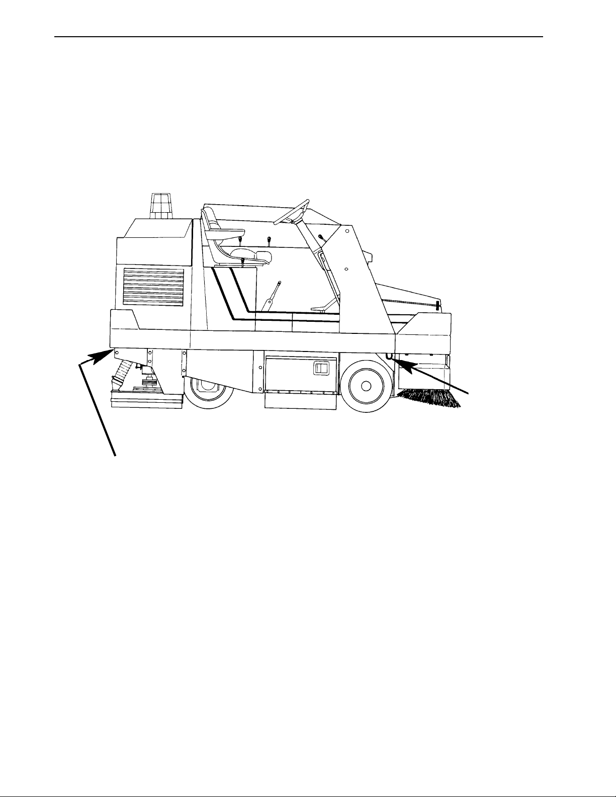
• the machine is tied down securely - see tie-down locations Figure 1
TigerCat, Hydro-Retriever 4500 Service Manual
1
GENERAL INFORMATION AND SAFETY
FIGURE 1
1 Tie-Down on
Each Side
2 Tie-Downs Under Rear Bumper
________________________________________________________________________________________________________________________________________________________________________________________________________________________________________________________________________
TOWING
The rear (drive) wheel should be lifted off of the ground for towing, to avoid damaging the hydrostatic drive
system. If the machine must be towed or pushed with the rear wheel on the ground, do not move the machine
faster than walking speed or a distance of more then 500 feet (150 meters).
TigerCat, Hydro-Retriever 4500 Service Manual
2
GENERAL INFORMATION AND SAFETY
________________________________________________________________________________________________________________________________________________________________________________________________________________________________________________________________________
GENERAL SAFETY INSTRUCTIONS
The words CAUTION!, WARNING!, and DANGER! are used in this manual to help you recognize situations
that may cause bodily injury or property damage. Carefully read information beginning with these words and
take necessary steps to protect personnel and property.
WARNING!
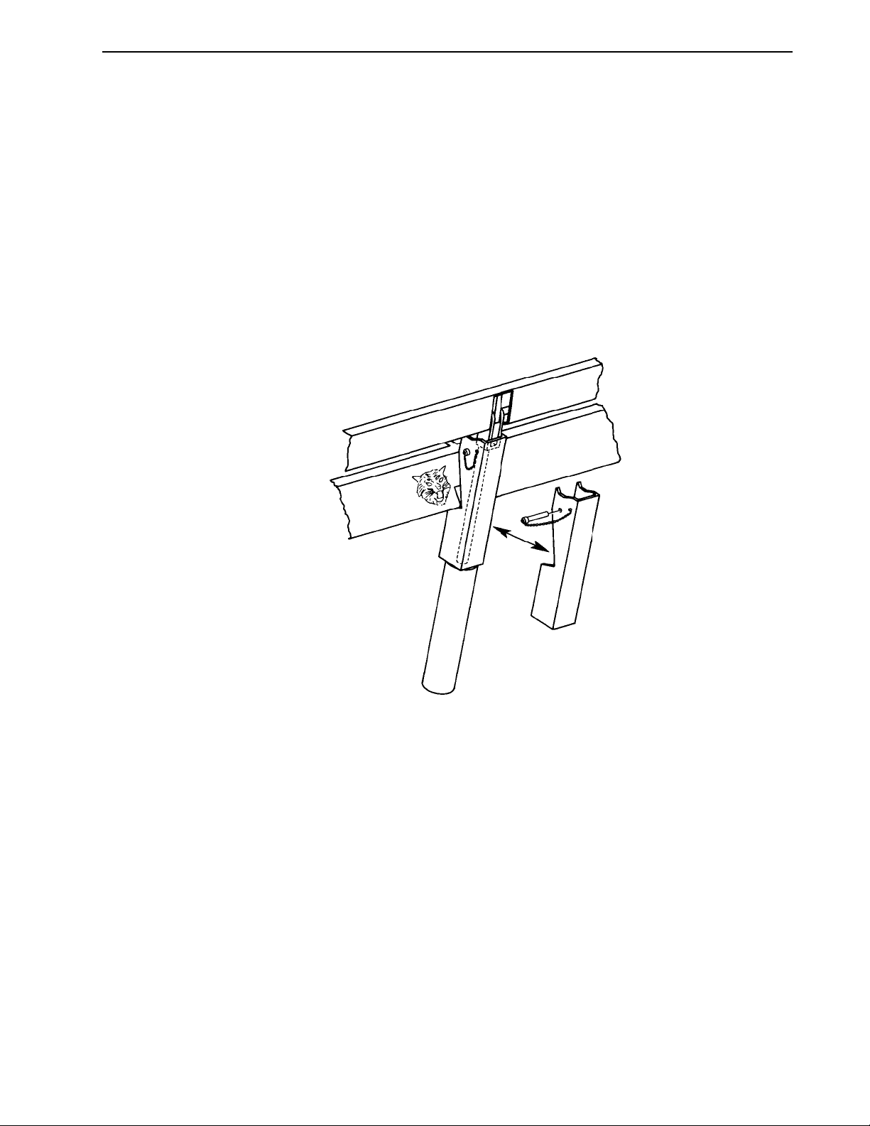
Never work under the hopper with out the hopper safety support installed on the hopper lift
cylinder, as shown in Figure 2, below.
FIGURE 2
WARNING!
Never work under the machine without safety stands or blocks installed under the frame.
DANGER!
Do not adjust the drive pedal linkage with the drive wheel on the floor. With the wheel on the floor, the
machine could move during adjustment, causing property damage or bodily injury.
WARNING!
Wear a protective mask to prevent inhaling of dust while servicing the dust control filter.
WARNING!
Wear eye protection while servicing the dust control filter.
TigerCat, Hydro-Retriever 4500 Service Manual
3

GENERAL INFORMATION AND SAFETY
________________________________________________________________________________________________________________________________________________________________________________________________________________________________________________________________________
GENERAL SAFETY INSTRUCTIONS (continued)
WARNING!
Do not allow loose clothing, jewelry or hair to become tangled in moving parts.
WARNING!
Use caution to prevent loose clothing or hair from being pulled into the engine cooling fan.
WARNING!
Remove all jewelry when working near electrical components.
DANGER!
Keep sparks and open flame away from the fuel tank, battery and engine compartment.
4
TigerCat, Hydro-Retriever 4500 Service Manual

SPECIFICATIONS AND MAINTENANCE
________________________________________________________________________________________________________________________________________________________________________________________________________________________________________________________________________
SPECIFICATIONS
Description English Metric
Cooling System Capacity 7 qts 6.6 l
Dust Control Filter Area 125 sq ft 11.6 sq m
Engine - See Page 63
Fuel Tank Capacity (Gasoline & Diesel) 10 gal 38 l
Hopper Capacity - Volume 15 cu ft 425 l
Hopper Capacity - Weight 1200 lbs 544 kg
Hydraulic System Capacity 18.5 gal 70 l
Hydraulic Oil Tank Capacity 17 gal 64 l
Minimum Aisle for U-turn 120 inches 305 cm
Recovery Tank Capacity 85 gal 322 l
Scrub Brush System
Brush Diameter 12 inches 38 cm
Brush Pressure 350 lbs 159 kg
Brush Speed 200 RPM 200 RPM
Scrub Path 45 inches 114 cm
Solution Tank Capacity 95 gal 360 l
Sweeping System
Main Broom Adjustment Pattern 2-1/2 inches 64 mm
Main Broom Minimum Bristle Length 2 inches 51 mm
Side Broom Diameter 21 inches 53 cm
Sweeping Width - Main Broom Only 45 inches 114 cm
Sweeping Width - with 1 Side Broom 56 inches 142 cm
Sweeping Width - with Dual Side Brooms 67 inches 142 cm
Tire, Rear 6 x 16 inches 15 x 41 cm
Tires, Front 4 x 16 inches 10 x 41 cm
Turning Radius - Left Turn 84 inches 213 cm
Turning Radius - Right Turn 88 inches 224 cm
Weight
Net 3800 lbs. 1723 kg
Shipping 4050 lbs 1837 kg
Ready to Run 5000 lbs 2268 kg
Wet Pickup System
Sealed Waterlift 40 inches 102 cm
Waterlift with 1 inch opening 38 inches 97 cm
TigerCat, Hydro-Retriever 4500 Service Manual
5

SPECIFICATIONS AND MAINTENANCE
________________________________________________________________________________________________________________________________________________________________________________________________________________________________________________________________________
DIMENSIONS
58 inches
(147 cm)
FIGURE 1
58-3/4 inches
(149cm)
108 inches (275 cm)
50 inches
(127 cm)
67-3/4 inches*
(172cm)
24-3/4 inches
(63 cm)
* 87 inches (221 cm) with Overhead Guard
TigerCat, Hydro-Retriever 4500 Service Manual
6
SPECIFICATIONS AND MAINTENANCE
________________________________________________________________________________________________________________________________________________________________________________________________________________________________________________________________________
Maintenance Chart
maintenance interval (hours of operation)
15 30 100 300
check engine coolant level •
check hydraulic oil level •
drain and flush solution tank •
flush solution valves •
inspect squeegee blades •
inspect, rotate main broom •
adjust main broom height •
adjust side broom •
blow dust out of radiator •
check oil in upper impeller housing •
inspect dust control filter •
change engine oil and filter •
lubricate (2) lower impeller shaft fittings * •
change oil in upper impeller housing •
* see Figure 2
FIGURE 2
Upper Impeller
Housing
Grease Fitting
Lower Impeller
Housing
Grease Fitting
Grease Fitting Locations as seen from the Engine Compartment
TigerCat, Hydro-Retriever 4500 Service Manual
7

SPECIFICATIONS AND MAINTENANCE
________________________________________________________________________________________________________________________________________________________________________________________________________________________________________________________________________
ADDITIONAL MAINTENANCE ITEMS
• Change the hydraulic oil filter when the “service filter” indicator light (on the dashboard) glows.
• Service the engine air filter whenever the red flag is visible in the filter service indicator (located in the
engine compartment, on the air filter). See page 64 for more information.
• Change the engine coolant every 1500 hours of operation. Use a 50/50 mixture of water and automotivetype anti-freeze.
• Every 1500 hours of operation, have a sample of the hydraulic oil analyzed for contamination. Change
the oil if necessary. See page 74 for more information.
• Every 1500 hours of operation, check the oil level in the scrub brush gear boxes. Add 140W gear lube if
necessary to bring oil level to 1-1/2 inches (3.8 cm) from top of gear boxes.
TigerCat, Hydro-Retriever 4500 Service Manual
8

SWEEPING SYSTEM
________________________________________________________________________________________________________________________________________________________________________________________________________________________________________________________________________
GENERAL INFORMATION
The main broom, the broom housing and the hopper are the main parts of the sweeping system. The main
broom lifts the dirt off of the floor and into the hopper. The broom housing and its skirts keep the litter and dust
from spreading beyond the sweeping path of the machine.
________________________________________________________________________________________________________________________________________________________________________________________________________________________________________________________________________
MAIN BROOM MAINTENANCE
The main broom should be serviced at regular intervals to maintain good sweeping performance. The following maintenance steps should be completed every 30 hours of operation.
1 Raise the hopper and install the hopper safety support. Then remove any debris wrapped around the
broom, broom motor shaft or idler hub.
2 Open the door at the right end of the broom housing and inspect the broom bristles. Rotate the broom if
the bristles are curved. Replace the broom if the bristles are worn to a length of 2 inches (5 cm) or less.
3 Clean built-up dirt from the inside of the broom housing.
4 Check main broom height adjustment.
TigerCat, Hydro-Retriever 4500 Service Manual
9

SWEEPING SYSTEM
________________________________________________________________________________________________________________________________________________________________________________________________________________________________________________________________________
MAIN BROOM ADJUSTMENTS
The working height of the main broom is adjustable to compensate for bristle wear. Before adjusting the main
broom height, measure the length of the bristles. The broom should be replaced if the bristles are worn to a
length of 2 inches (5 cm) or less.
To adjust the main broom height...
1 Drive the machine to an area with a level floor and set the parking brake.
2 With the engine still running, put the broom switch in the ON position and the main broom lever in the
SWEEP position. Do not move the machine. Let the main broom run for about 1 minute. This allows the
broom to polish a “strip” on the floor.
3 After 1 minute, release the parking brake and move the machine so that the polished strip is visible. The
polished strip on the floor should be 2-1/2 inches (6.3 cm) wide.
Note: Adjusting the broom for a pattern wider than specified decreases sweeping performance and increases
broom wear.
4 If the polished strip is too wide or too narrow, remove the panel from the left side of the operator’s
compartment (next to the operator’s left leg). The broom adjustment knob is behind this panel, near the
bottom of the broom raise/lower lever. Turn the broom adjustment knob clockwise to make the polished
strip wider or counter-clockwise to make the polished strip narrower.
5 Check the broom pattern again. Continue adjusting until the polished strip is the correct width.
Main Broom Level Adjustment
The broom level adjustment raises or lowers just the left end of the main broom, so that the broom touches the
floor evenly across it’s entire length.
Once the broom is leveled at the factory, further adjustment is seldom necessary. Adjust the broom level only
if the broom pattern (see main broom adjustment) is tapered after installing a new broom.
To adjust the broom level...
1 Install a new broom and check the broom pattern (see Main Broom Adjustment). If the broom pattern is
tapered, go to step 2. If the broom pattern is not tapered, the broom level does not need adjustment.
2 Remove the (7) screws holding the cover at the left end of the broom housing.
TigerCat, Hydro-Retriever 4500 Service Manual
10
SWEEPING SYSTEM
________________________________________________________________________________________________________________________________________________________________________________________________________________________________________________________________________
MAIN BROOM ADJUSTMENTS (continued)
3 Loosen the (2) “A” bolts (see Figure 1) and lock nuts “B” and “E”.
4 To raise the left end of the broom, turn bolts “C” and “D” downward. To lower the left end of the broom,
turn the bolts upward.
5 Check the broom pattern again. Continue adjusting bolts “C” and “D” until the width of the broom pattern
is the same from one end to the broom to the other.
C
FIGURE 1
Main Broom Options
Two different main brooms are available for the TigerCat.
F
G
A
B
E
D
• The 8 row polypropylene broom (part number 505071) is an all purpose broom for light litter or dust.
• The 8 row proex and wire broom is best for heavier debris. The wire bristles also help break compacted
dirt loose from the floor.
TigerCat, Hydro-Retriever 4500 Service Manual
11
SWEEPING SYSTEM
________________________________________________________________________________________________________________________________________________________________________________________________________________________________________________________________________
MAIN BROOM ADJUSTMENTS (continued)
Rotating or Replacing the Main Broom
Since the main broom motor always turns in the same direction, the bristles eventually become curved. When
this occurs, sweeping performance can be improved by removing the broom and turning it around (end for
end) so that it will turn in the opposite direction. This procedure is commonly referred to as “rotating” the main
broom.
Note: The main broom should be replaced when its bristles are worn to a length of 2 inches (5 cm) or less.
To rotate or replace the main broom...
1 Raise the hopper, stop the engine, set the parking brake and put the hopper safety support on the hopper
lift cylinder.
2 Put the main broom lever in the SWEEP position.
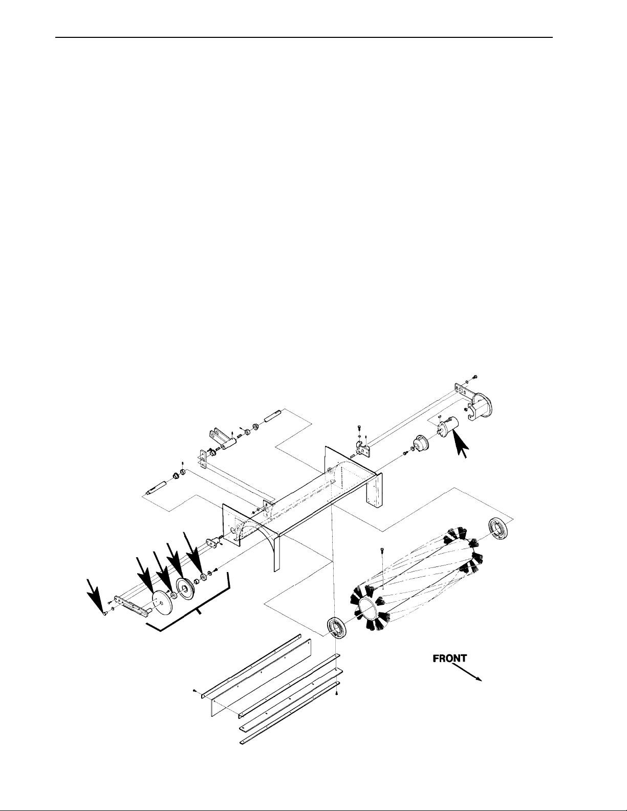
3 Open the main broom access door (on the right side of the machine) and remove the “A” bolts (see
Figure 2).
FIGURE 2
F
E
C
E
D
A
B
TigerCat, Hydro-Retriever 4500 Service Manual
12

SWEEPING SYSTEM
________________________________________________________________________________________________________________________________________________________________________________________________________________________________________________________________________
MAIN BROOM ADJUSTMENTS (continued)
4 Pull idler assembly “B” away from the broom and.pull the broom out of the broom housing.
5 Remove any debris wrapped around idler hub “C”. If the hub doesn’t turn freely, remove it from the idler
assembly and look for debris between the hub and string guard “D”. Also check the “E” idler bearings,
replace them if necessary.
6 From the front of the broom housing, remove any debris wrapped around broom motor “F”. Install a seal
kit or replace the motor if it is leaking hydraulic oil.
7 Inspect the rubber skirts on the sides and the back of the broom housing, replace any skirt that’s torn or
damaged.
8 Inspect the hopper skirt (drags on the floor in front of the main broom). Replace the skirt if it’s torn or
damaged.
9 If the broom is not worn out, remove any debris wrapped around it, flip it (end for end) and slide it back
into the broom housing.
10 Push on the broom and turn it by hand until you feel the lugs on the drive hub engage the hub inside the
broom.
11 Install the idler assembly and the bolts that hold it in place.
Note: If the idler assembly doesn’t fit properly, the hub in the broom is probably not engaged on the drive hub.
Remove the idler and try seating broom on the drive hub again.
12 Close the broom door and check the main broom height adjustment.
Note: The broom height must be adjusted whenever a new broom is installed.
TigerCat, Hydro-Retriever 4500 Service Manual
13

SWEEPING SYSTEM
________________________________________________________________________________________________________________________________________________________________________________________________________________________________________________________________________
MAIN BROOM ADJUSTMENTS (continued)
Main Broom Motor Removal
1 Open the door at the right end of the broom housing and remove the idler assembly from the end of the
broom. Then pull the broom out of the broom housing.
2 Remove the (7) screws holding the cover at the left end of the broom housing.
3 Note the position of the hydraulic hoses and disconnect them from the broom motor. Install plugs in the
hoses to keep the oil in and the dirt out of the hydraulic system.
4 Loosen the lock nut “B” (see Figure 1) and loosen bolt “C” one turn.
5 Remove the (6) screws from the broom housing end panel.
6 Remove set screw “F” and the (2) “A” bolts from motor arm “G” and pull the motor and arm out of the
broom housing.
7 Remove the motor from the arm and the drive hub from the motor. Repair or replace the motor as
necessary.
Follow the steps in reverse order to re-install the motor.
TigerCat, Hydro-Retriever 4500 Service Manual
14

SWEEPING SYSTEM
________________________________________________________________________________________________________________________________________________________________________________________________________________________________________________________________________
BROOM HOUSING SKIRTS
Rubber or urethane skirts are installed at the front, back and sides of the broom housing to keep dust and
debris confined during sweeping. For good sweeping performance, all of these skirts must be in good condition and adjusted for proper contact with the floor.
Hopper Skirt
The hopper skirt is mounted on the hopper and drags on the floor in front of the main broom. It acts as a
ramp, to help guide the litter off the floor and into the hopper. It also acts like a check valve, keeping litter from
being thrown forward by the rotation of the broom.
To replace the hopper skirt...
1 Raise the hopper about 3 feet (1 meter) and put jack stands under it for additional support.
WARNING!
Never work under the hopper without jack stands in place to support it.
2 Remove the screws holding the skirt on the hopper and install the new skirt in it’s place.
Replacing Skirts at Left End of Broom Housing
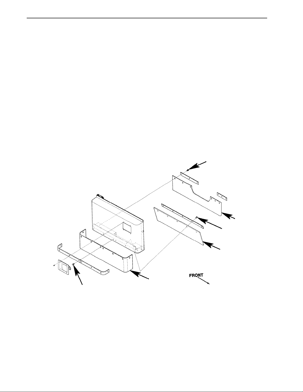
Outer skirt - Remove the (8) “A” bolts (see Figure 3) and the straps holding the skirt in place.
C
A
D
Outer
B
FIGURE 3
Middle
E
F
Inner
TigerCat, Hydro-Retriever 4500 Service Manual
15
SWEEPING SYSTEM
________________________________________________________________________________________________________________________________________________________________________________________________________________________________________________________________________
BROOM HOUSING SKIRTS (continued)
Middle Skirt - Remove the (7) “B” bolts and cover “C”. Then remove the “D” bolts and the straps holding the
middle skirt in place.
Inner Skirt - Remove the (7) “B” bolts and cover “C”. Then remove the (6) “E” bolts and the straps holding the
middle skirt in place. When installing the new middle skirt, position it so that area of the skirt marked “F” is on
the inside (broom-side) of panel “G” - not between the the strap and panel “G”. The holes at area “F” are not
actually used to hold the skirt in place.
Follow steps in reverse order to reassemble.
Replacing Skirts at Right (door) End of Broom Housing
Outer Skirt - Remove the (8) “H” bolts (see Figure 4) and the straps holding the skirt in place.
I
FIGURE 4
Inner
J
Middle
Outer
H
Middle Skirt - Open the broom access door, remove the (6) “I” bolts, straps and the inner skirt. Then remove
the (5) “J” bolts and the strap holding the middle skirt in place.
Inner Skirt - Open the broom access door, remove the (6) “I” bolts, straps and the inner skirt.
Follow steps in reverse order to reassemble.
TigerCat, Hydro-Retriever 4500 Service Manual
16

SWEEPING SYSTEM
________________________________________________________________________________________________________________________________________________________________________________________________________________________________________________________________________
BROOM HOUSING SKIRTS (continued)
Replacing the skirt at the back of the broom housing
1 Raise the hopper and install the hopper safety support.
2 Open the broom access door and remove the broom from the machine.
3 If the heads of the skirt mounting bolts face toward the front of the machine, remove the bolts, strap and
skirt.
4 If the heads of the skirt mounting bolts face toward the back of the machine, reach under the skirt to
remove the bolts. Install the new skirt so the strap and bolt heads face toward the front of the machine.
This will make future service easier.
5 Follow steps in reverse order to reassemble.
TigerCat, Hydro-Retriever 4500 Service Manual
17
SWEEPING SYSTEM
________________________________________________________________________________________________________________________________________________________________________________________________________________________________________________________________________
SIDE BROOM
The side broom is designed to move dust and debris from along a curb or wall, into the path of the main
sweeping broom.
Side Broom Height Adjustment
The side broom should be positioned so that the bristles from the “10 o’clock “ position to the “3 o’clock”
position (as viewed from the operator’s seat) touch the floor.
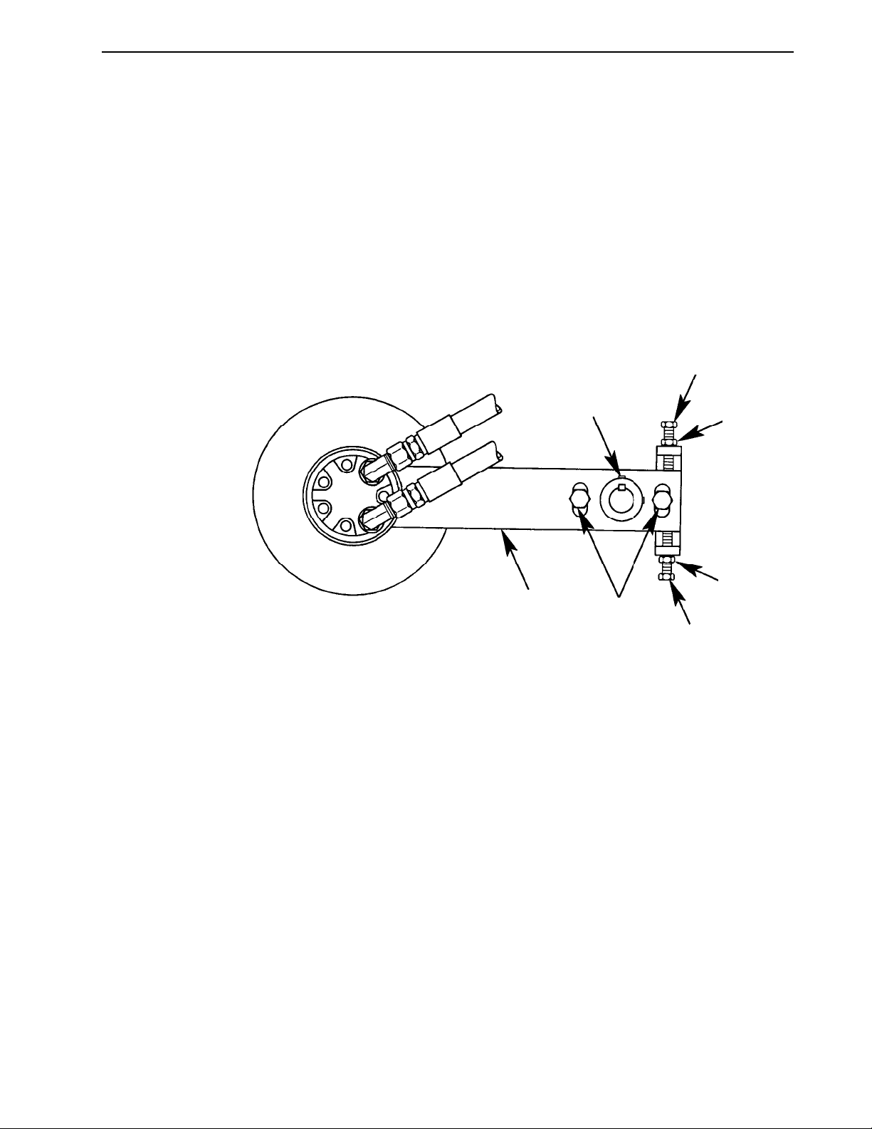
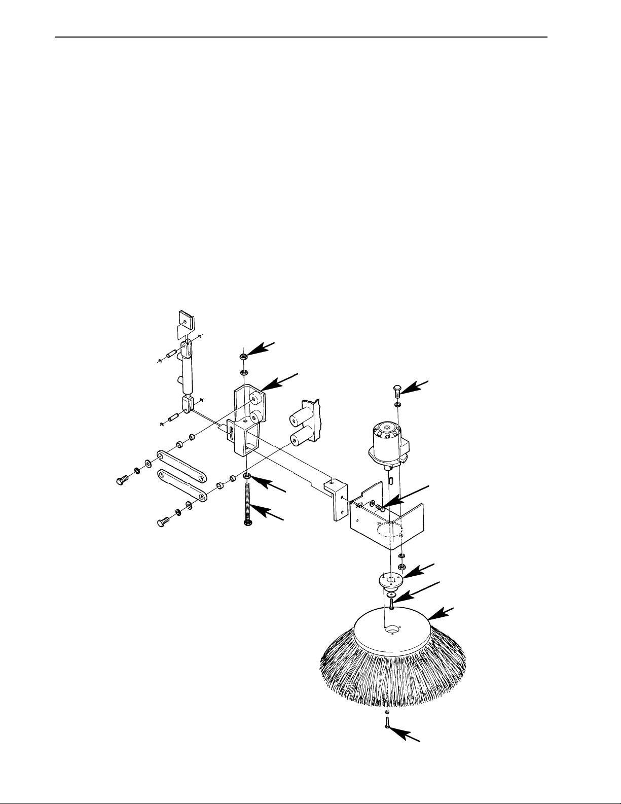
To adjust for broom, loosen the lock nut “C” (see Figure 5) and turn bolt “D” clockwise to lower (or counterclockwise to raise) the side broom. Check the adjustment with the side broom running. Then tighten lock nut
“C”.
C
E
C
D
H
J
G
F
B
FIGURE 5
TigerCat, Hydro-Retriever 4500 Service Manual
18
A

SWEEPING SYSTEM
________________________________________________________________________________________________________________________________________________________________________________________________________________________________________________________________________
SIDE BROOM (continued)
Side Broom Angle Adjustment
The side-to-side tilt of the side broom is adjustable. Once adjusted at the factory, re-adjustment is seldom
necessary. If adjustment is required, loosen the (2) “J” bolts (see Figure 5), tilt the broom to the desired angle
and re-tighten the bolts.
Check the adjustment with the side broom running. The broom should touch the floor from the “10 o’clock”
position to the “3 o’clock” position, as viewed from the operator’s seat.
Side Broom Motor Removal
1 Raise hooper and install the hopper safety support on the hopper lift cylinder.
WARNING!
Never work under the hopper without the hopper safety support installed on the hopper lift cylinder.
2 Remove the side broom guard from the frame (3 bolts).
3 Remove the (3) “A” bolts (see Figure 5).
4 Support the motor, remove lock nut “K” and bolt “D”.
5 Remove the (2) “H” bolts and separate the motor from the mount.
6 Note the position of the hydraulic hoses and disconnect them from the broom motor. Install plugs in the
hoses to keep oil in and dirt out of the hydraulic system.
7 Repair or replace the motor as necessary.
Follow the steps in reverse order to re-install the motor.
TigerCat, Hydro-Retriever 4500 Service Manual
19
SWEEPING SYSTEM
________________________________________________________________________________________________________________________________________________________________________________________________________________________________________________________________________
HOPPER ADJUSTMENTS
1 Remove the broom from the broom housing.
2 Look into the broom housing to see if the seals at the sides of the hopper opening are parallel to and
sealed against the sides of the broom housing.
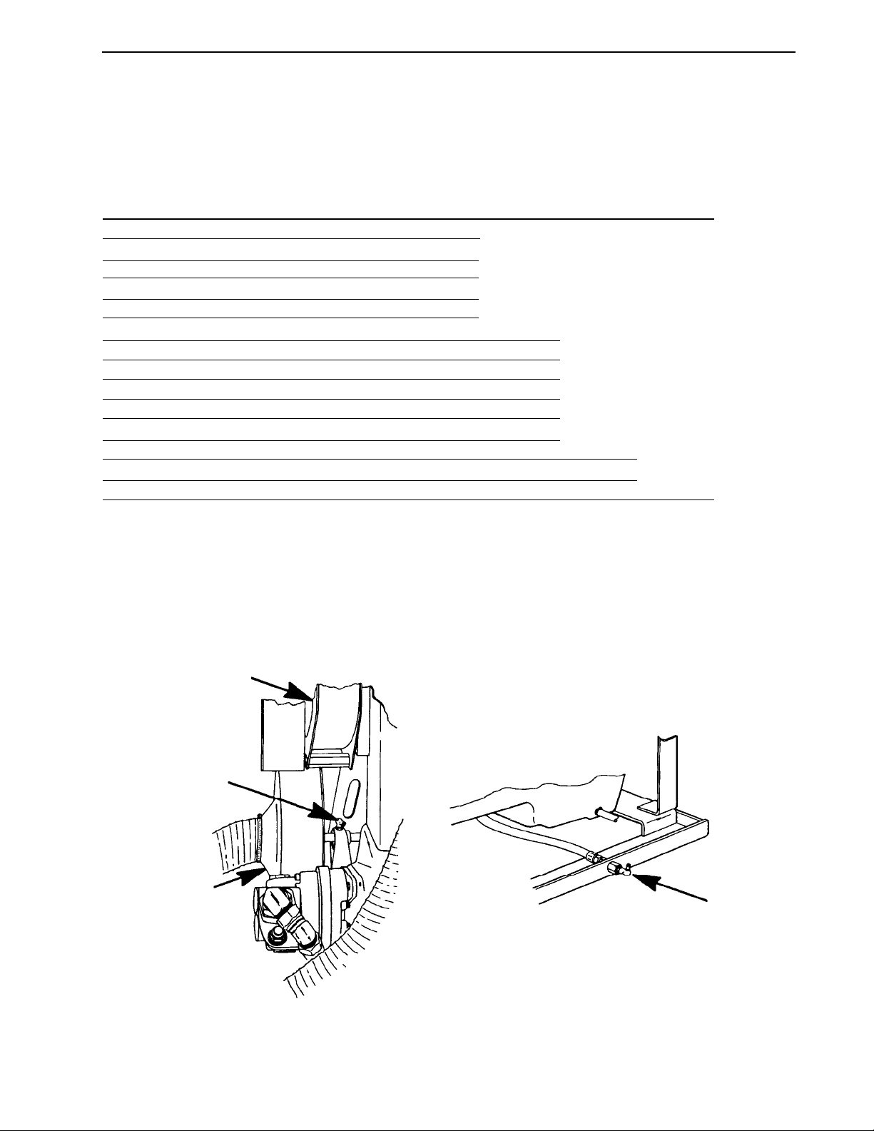
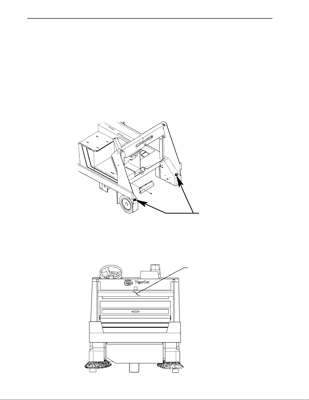
3 If they are not, adjust hopper angle bolts “A” (see Figure 6). Turn the bolts counter-clockwise to raise the
front of the hopper. Turn the bolts clockwise to lower the front of the hopper. Adjust both bolts equally.
FIGURE 6
A
4 Watch channel “B” (see Figure 7) as you lower the hopper. Channel “B” should flex 1/8 inch downward
after the hopper stops moving. If the channel does not flex or flexes more than 1/8 inch, the stroke of the
hopper lift cylinder should be adjusted.
B
FIGURE 7
TigerCat, Hydro-Retriever 4500 Service Manual
20

SWEEPING SYSTEM
________________________________________________________________________________________________________________________________________________________________________________________________________________________________________________________________________
HOPPER ADJUSTMENTS (continued)
To adjust the cylinder...
1 Hold the hopper switch in the HOPPER UP position just long enough for the hopper to tilt forward.
2 Reach behind the top of the hopper, loosen the lock nut on the hopper cylinder rod and turn the rod
clockwise to increase downward flex of channel “B” or counter clockwise to decrease downward flex of
channel “B”.
3 Close the hopper and check your adjustment. Repeat adjustment if necessary. If adjustment is good, tilt
hopper again and tighten the lock nut on the cylinder rod.
Hopper Dump Door Adjustment
The gasket on the dump door must seal air tight against the front of the hopper for proper machine operation.
Before adjusting the dump door cylinders, check the condition of the gasket and replace it if damaged. To
adjust the hopper door cylinders, loosen the lock nuts on the cylinder rods and turn the cylinder rods.
TigerCat, Hydro-Retriever 4500 Service Manual
21

SWEEPING SYSTEM
________________________________________________________________________________________________________________________________________________________________________________________________________________________________________________________________________
SWEEPING SYSTEM TROUBLESHOOTING
Problem: Debris left on the floor
Possible Cause and Remedy:
1 Operator running machine with engine speed switch in the IDLE position - instruct operator to run ma-
chine with switch in HIGH.
2 Operator driving machine too fast.
3 Hopper full - empty hopper.
4 Main broom not touching floor - adjust broom height.
5 Main broom worn out - replace and adjust main broom.
6 Debris wrapped around main broom.
7 Skirts around main broom torn or missing - replace torn skirts.
TigerCat, Hydro-Retriever 4500 Service Manual
22
DUST CONTROL SYSTEM
________________________________________________________________________________________________________________________________________________________________________________________________________________________________________________________________________
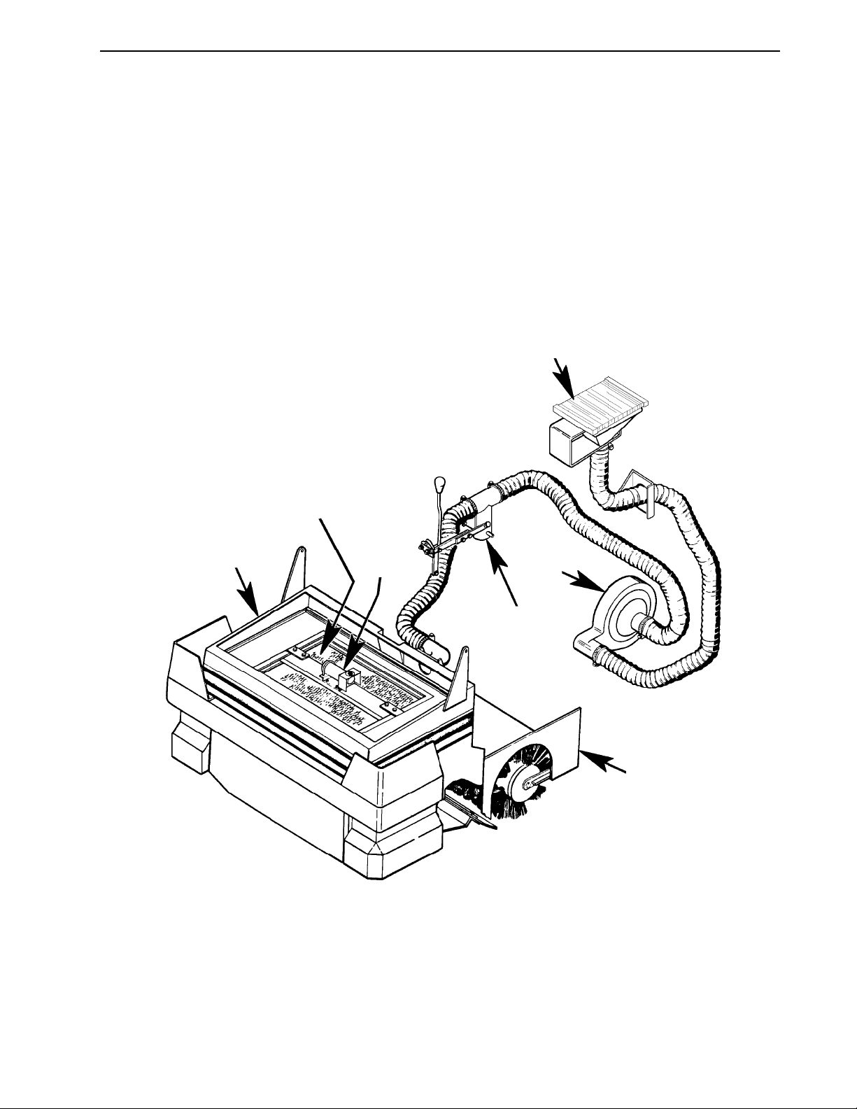
GENERAL INFORMATION
The dust control system prevents dust from flowing out of the broom housing and polluting the air around the
machine.
Air enters the dust control system through gaps in the broom housing skirts. The air stream carries dust
(raised by the broom) through the broom housing, through the hopper and into the dust control filter. The dust
gets trapped in the filter. The air continues through the filter, through the dust control (lower) impeller, through
the hydraulic oil cooler and out of the machine.
Hydraulic Oil Cooler
FIGURE 1
Hopper
Dust
Control
Filter
Shaker
Motor
Lower
Impeller
Dust
Control
Valve
Broom Housing
As more and more dirt builds up on the filter, less air can go through the system. Eventually, dust will flow out
of the broom housing because there is not enough airflow to carry it into the filter. When this happens, the
operator can easily clean the filter by moving the dust control lever to the SHAKE position. This starts a motor
(on top of the filter) that shakes the dirt out of the filter and into the hopper.
TigerCat, Hydro-Retriever 4500 Service Manual
23

DUST CONTROL SYSTEM
________________________________________________________________________________________________________________________________________________________________________________________________________________________________________________________________________
GENERAL INFORMATION (continued)
When sweeping on a wet surface the dust control lever should be put in the OFF position. This opens a
butterfly-type valve which stops air flow. If this procedure is not followed, moisture will be pulled into the filter,
mix with the dirt and form a hardened coating that is difficult to remove.
There is no dust control for the side broom. The side broom should be used only when sweeping along a wall
or curb, and raised when sweeping in an open area. This will keep the amount of dust raised by the machine
to a absolute minimum.
________________________________________________________________________________________________________________________________________________________________________________________________________________________________________________________________________
DUST CONTROL FILTER REMOVAL AND INSPECTION
The dust control filter should be inspected every 30 hours of operation. To inspect the filter...
1 Open the hinged cover on top of the hopper. If there is dirt under this cover, the gasket around the filter
may be damaged or the filter may be punctured. The filter must be replaced if it is punctured.
2 Disconnect the shaker motor wiring, release the filter latches and lift the filter retainer out of the hopper.
3 Using the lifting rings, carefully lift the filter out of the hopper.
4 Inspect the gasket around the dirty-side of the filter. Replace this filter if it is damaged or pulled loose
from the filter.
5 Check the dirty side of the filter for a heavy build-up of dirt. If The filter is lightly coated (1/16 inch thick)
with dirt and the pleats in the filter are not filled with dirt, cleaning is not necessary. If there is a heavy
coating of dirt on the filter, follow the cleaning instructions below.
TigerCat, Hydro-Retriever 4500 Service Manual
24

DUST CONTROL SYSTEM
________________________________________________________________________________________________________________________________________________________________________________________________________________________________________________________________________
CLEANING THE DUST CONTROL FILTER
WARNING!
Wear a protective mask to prevent inhaling of dust while servicing the filter.
WARNING!
Wear eye protection while servicing the filter.
CAUTION!
Be careful not to puncture the filter while cleaning.
1 Use a vacuum cleaner to remove as much dirt as possible from the filter.
2 Blow compressed air (100 PSI maximum pressure) into the clean side of the filter (in the opposite direc-
tion of normal air flow).
3 If there is still hardened dirt built-up in the filter, soak it in warm water for 15 minutes. Then rinse it under
a gentle stream of water (40 PSI maximum pressure). Let the filter dry completely before putting it back
into the machine.
4 Inspect the gasket around the filter. Replace it if it is damaged or torn away from the filter.
TigerCat, Hydro-Retriever 4500 Service Manual
25
DUST CONTROL SYSTEM
________________________________________________________________________________________________________________________________________________________________________________________________________________________________________________________________________
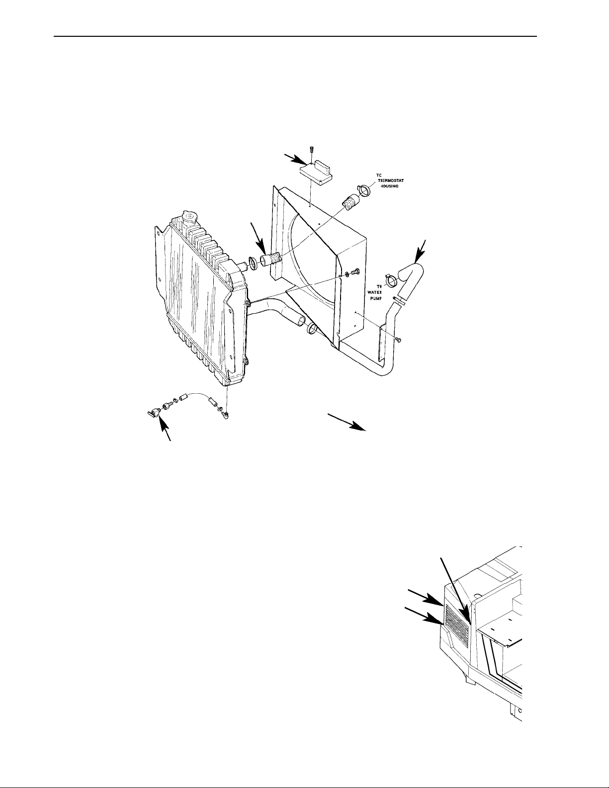
LOWER IMPELLER BELT, SHAFT OR BEARING REPLACEMENT
1 Drain cooling system, using drain valve “A” (see Figure 2).
B
D
C
Front
FIGURE 2
A
2 Disconnect the electrical connector and the vacuum hose from Ignition controller “B”.
3 Disconnect hose “C” from the water pump.
4 Disconnect hose “D” from the top of the radiator.
E
5 Remove the “E” bolts from grill panel “F” (see Figure 3).
6 Pull the back side of the radiator away from the machine
and backward to work the radiator assembly out of the
machine.
F
E
FIGURE 3
TigerCat, Hydro-Retriever 4500 Service Manual
26
 Loading...