

Page 1
ArrayMasStor
J Series
(19” Rack Model, Tower Model )
USER’S MANUAL
P/N A208233
Revision 1.2e
Page 2
Page 3
Advanced Technology and Systems Co., Ltd.
II
WARNING
l The AC power cord must be connected to a grounded outlet. In case of a short-circuit,
electrical shock or fire may occur.
l Do not use the ArrayMasStor in hot, humid or dusty environments. Usage under such
conditions may result in a short circuit, electrical shock or fire.
l The ArrayMasStor's cover must be securely attached to the chassis. If the cover is not
properly installed, ventilation could be impaired and this may cause a short circuit,
electrical shock or fire.
l Do not block the ventilation opens. Without proper ventilation, the ArrayMasStor will
malfunction or fail.
l Use the supplied AC power cord. In case of a short circuit, electrical shock or fire may
occur.
CAUTION
l Rapid temperature changes may cause condensation of humidity to form on the
ArrayMasStor. Do not use the subsystem where it will not evaporate.
l Do not install the ArrayMasStor near electronic components with strong
electromagnetic fields, such as televisions or loud speakers.
l Turn off the power before moving, connecting or disconnecting the ArrayMasStor.
This will prevent vibrations or mechanical shocks from damaging the hard disk drives
(HDD) and other internal components.
l Do not remove the drive unit during normal operation, as this may cause damage,
malfunction or data loss. The drive unit should be removed when they have failed and
need to be replaced.
l Use the appropriate SCSI host card for ArrayMasStor in accordance with single-ended
or low voltage differential (LVD) SCSI interface. Using the wrong card may damage
the subsystem or cause a malfunction to occur.
l Use only the approved replacement drive unit in the ArrayMasStor. Please see
Appendix D for a list of approved replacement parts.
Page 4

ArrayMasStor J Series User’s Manual
III
l Do not turn on and off in a rapid succession manner. Leave at least 15 seconds
between turning on and off. This may avoid damage or malfunction. The HDD
requires about 15 seconds to completely stop after turning off the ArrayMasStor.
l Insert to push the drive unit firmly. A loose connection may damage the
ArrayMasStor or cause it to malfunction.
l Do not turn the ArrayMasStor off by unplugging the AC power cord from the rear
panel. This may result in data loss. The ArrayMasStor’s firmware is designed to
detect the status of the power switch and synchronize the data in the cache and the
drives before shutdown. To control the power from the AC line, send a ‘synchronize
cache’1 command from the host computer to the ArrayMasStor.
l When unplugging the AC power cord, leave one minute further before plugging it
again. This may prevent fuse damage.
IMPORTANT !
l For optimum performance, the total length of the SCSI bus should be as short as
possible. The total cable length must be less than 1.5 m for single-ended mode and
12m for LVD mode.
l A maximum of two host computers can be connected to the ArrayMasStor in a dual
host configuration.
l Set the ArrayMasStor’s UNIX2 C/H/S mode before connecting it to the operating
systems shown below. Changing the UNIX C/H/S mode after installation may cause
data loss.
Solaris3(SPARC) 2.X
IRIX4 5.X
l The backlight on the liquid crystal display (LCD) turns off automatically when the
operation buttons are not used for a period of time. The backlight will turn on when
the operation button is pressed. The backlight will stay on when a drive fails, when
the ArrayMasStor is in data reconstruction mode, and during data initialization.
1
A SCSI command which ensures that logical blocks in the cache have their most recent data
value recorded in the drives.
2
UNIX has two known standards, System V by AT&T and BSD4.x by Berkeley University.
3
Solaris™ and Spark™ is a Trademark of SUN Microsystems.
4
IRIX ™ is a Trademark of Silicon Graphics Inc.
Page 5

Advanced Technology and Systems Co., Ltd.
IV
l It is strongly recommended that up to two ArrayMasStors be connected to the same
bus in the single-ended SCSI.
l It is strongly recommended that the data be regularly backed up. In RAID levels 1 and
5, the ArrayMasStor will be operative when a drive fails. However, if two or more
drives fail, all of the data may not be recoverable. And, if any other parts of the
ArrayMasStor malfunction, there is possibility of data loss.
l It is strongly recommended that the surface verification check implement before
dynamic data reallocation.
l It is strongly recommended that an interruptible power supply (UPS) be used with the
ArrayMasStor to avoid data loss when the power line is unstable and power outrage
happens.
Page 6

ArrayMasStor J Series User’s Manual
V
Table of Contents
Foreword ..……………………………………...………………………………………………………………….………I
Safety Notice ..………………………………...………………………………………………………………….………I
WARNING....………………………………...………………………………………………………………….………II
CAUTION....…………….…………………...………………………………………………………………….………II
IMPORTANT……….…………………………………………………………………………………………………..III
1 INTRODUCTION TO THE ARRAYMASSTOR J SERIES............................................................1
1.1 FEATURES......................................................................................................................................1
1.2 ABOUT RAID LEVELS ....................................................................................................................2
1.2.1 RAID Level 0..........................................................................................................................2
1.2.2 RAID Level 1..........................................................................................................................3
1.2.3 RAID Level 5..........................................................................................................................4
1.3 MIXED RAID LEVELS ....................................................................................................................5
1.4 HOT SPARE FEATURE.....................................................................................................................6
1.5 WRITE BACK CACHE FUNCTION .....................................................................................................7
1.6 DYNAMIC DATA REALLOCATION ....................................................................................................8
2 NAMING CONVENTION ...................................................................................................................9
2.1 FRONT VIEW ..................................................................................................................................9
2.2 REAR VIEW................................................................................................................................. 13
3 INSTALLING THE ARRAYMASSTOR J SERIES .......................................................................15
3.1 CONNECTING THE POWER LINE CORD...........................................................................................15
3.2 CONNECTING THE SCSI CABLE ....................................................................................................15
3.3 TURNING THE POWER ON .............................................................................................................15
3.4 SETTING THE PASSWORD..............................................................................................................16
3.5 SETTING THE TIME & DATE.......................................................................................................... 16
3.6 SETTING THE SCSI ID..................................................................................................................16
3.7 SETTING THE SPARE MODE AND RECONFIGURING THE LUN ..........................................................16
3.8 FORMATTING...............................................................................................................................16
3.9 CONNECTION TO A MACINTOSH ................................................................................................... 16
3.10 CONNECTION TO THE UNIX SYSTEMS.......................................................................................17
4 ARRAYMASSTOR J SERIES OPERATIONS .............................................................................. 18
4.1 OPERATION BUTTONS .................................................................................................................. 18
4.2 STATUS DISPLAY (MAIN MENU)...................................................................................................19
4.2.1 Normal Mode .......................................................................................................................19
4.2.2 Degraded Mode (drive failure)..............................................................................................20
4.2.3 Drive Replacement ............................................................................................................... 21
4.2.4 Data Reconstruction.............................................................................................................21
4.2.5 Data Initialization ................................................................................................................22
4.2.6 Data Reallocation.................................................................................................................22
4.2.7 Double Fault (Failure of two or more drives)........................................................................ 23
4.2.8 Forced Data Reconstruction.................................................................................................24
4.2.9 System Halt ..........................................................................................................................25
4.2.10 Fan Failure.......................................................................................................................26
4.2.11 Power Supply Failure........................................................................................................27
4.2.12 Surface Check...................................................................................................................28
4.3 LUN CONFIGURATION ................................................................................................................. 29
4.4 CHS INFORMATION......................................................................................................................29
4.5 SCSI ID INFORMATION ................................................................................................................30
4.6 DISPLAY SYSTEM CONFIGURATION ...............................................................................................30
Page 7

Advanced Technology and Systems Co., Ltd.
VI
4.6.1 Number of Drives................................................................................................................. 30
4.6.2 Hot Spare Drive...................................................................................................................30
4.6.3 Buzzer Mode........................................................................................................................30
4.6.4 Automatic Reconstruction Mode...........................................................................................30
4.6.5 Write Cache Mode ...............................................................................................................31
4.6.6 AIX Error Notice Mode........................................................................................................31
4.6.7 UNIX C/H/S Mode ...............................................................................................................31
4.6.8 Ultra SCSI Mode.................................................................................................................. 31
4.6.9 Initiator Mode ...................................................................................................................... 31
4.6.10 Background Surface Check...............................................................................................31
4.6.11 DPO/FUA Bit...................................................................................................................32
4.7 SYSTEM STATUS..........................................................................................................................33
4.7.1 System Status....................................................................................................................... 33
4.7.2 Serial Number...................................................................................................................... 34
4.7.3 Microcode Revision.............................................................................................................. 34
4.7.4 System Status Code .............................................................................................................. 34
4.7.5 System Status Time and Date ................................................................................................ 34
4.8 DRIVE STATUS ............................................................................................................................ 35
4.9 CHANGING SYSTEM CONFIGURATION ........................................................................................... 36
4.9.1 Entering the Password ......................................................................................................... 36
4.9.2 Changing the Date and Time Setting .................................................................................... 37
4.9.3 Changing the SCSI ID..........................................................................................................38
4.9.4 Reconfigure ......................................................................................................................... 39
4.9.5 Buzzer Test .......................................................................................................................... 41
4.9.6 Changing the Buzzer Mode...................................................................................................41
4.9.7 Configuring the Write Cache Mode ...................................................................................... 42
4.9.8 Changing the Automatic Reconstruction Mode .....................................................................43
4.9.9 Maximum SCSI Transfer Rate .............................................................................................. 44
4.9.10 DPO/FUA Bit...................................................................................................................45
4.9.11 Changing the AIX Error Notice Mode............................................................................... 46
4.9.12 Changing the UNIX C/H/S Mode ...................................................................................... 47
4.9.13 Performing Surface Check................................................................................................ 48
4.9.14 Stopping Surface Check.................................................................................................... 49
4.9.15 Background Surface Check...............................................................................................50
4.9.16 Setting Initiator Mode.......................................................................................................51
4.9.17 Error Insertion................................................................................................................. 52
4.9.18 Displaying the System Trace Data .................................................................................... 53
4.9.19 Erasing the System Trace Data......................................................................................... 53
4.10 ADDING DRIVE UNITS.............................................................................................................. 54
4.10.1 Adding Unit as Hot Spare Drive........................................................................................55
4.10.2 Adding Unit as Data Drive ...............................................................................................56
4.10.3 Adding Unit as New LUN..................................................................................................57
4.11 REMOVING ON-LINE DRIVES.....................................................................................................58
5 TROUBLESHOOTING .................................................................................................................. 59
5.1 DRIVE FAILURE ........................................................................................................................... 59
5.2 POWER SUPPLY MODULE FAILURE............................................................................................... 60
5.3 FAN MODULE FAILURE................................................................................................................ 61
5.4 OTHER FAILURES......................................................................................................................... 62
APPENDIX A SPECIFICATIONS....................................................................................................... 63
APPENDIX B ACCESSORIES ............................................................................................................ 65
APPENDIX C DEFAULT CONFIGURATION..................................................................................66
Page 8

ArrayMasStor J Series User’s Manual
VII
APPENDIX D REPLACEMENT PARTS............................................................................................67
APPENDIX E FEATURE SETTING ...................................................................................................68
ELECTRONIC EMISSION NOTICES..................................................................................................69
FEDERAL COMMUNICATIONS COMMISSION (FCC) STATEMENT................................................................69
FCC WARNING................................................................................................................................... 69
INFORMATION.....................................................................................................................................70
- MANUFACTURER..................................................................................................................................70
Page 9

Page 10

ArrayMasStor J Series User’s Manual
1
1 Introduction to the ArrayMasStor J Series
The ArrayMasStor J Series is a compact, high performance, redundant array of independent disks.
The subsystem includes up to four hard disk drives (HDD) and offers high availability and an
excellent data transfer rate. The subsystem is easy to install and use, and has a unique interoperability
feature that allows it to work through a simple SCSI interface and be recognized as a single drive by a
host computer.
1.1 Features
The ArrayMasStor J Series
l Stores a large capacity data securely with excellent performance and data availability.
l Allows a failed drive to replace without interrupting system operation. Data
reconstruction starts automatically upon drive replacement.
l Data reconstruction onto the spare drive starts immediately when a drive fails. (hot spare
mode)
l Improves write performance with large-capacity cache buffer.
l Recognized as a single drive on the SCSI bus. The ‘daisy chained’ SCSI connection can
be extended extremely a large storage capacity.
l Complies with the standard SCSI-3 interface.
l Provides dynamic data reallocation and background surface verification for maximum
system availability.
l Allows mixed RAID levels within the one product.
Page 11
Advanced Technology and Systems Co., Ltd.
2
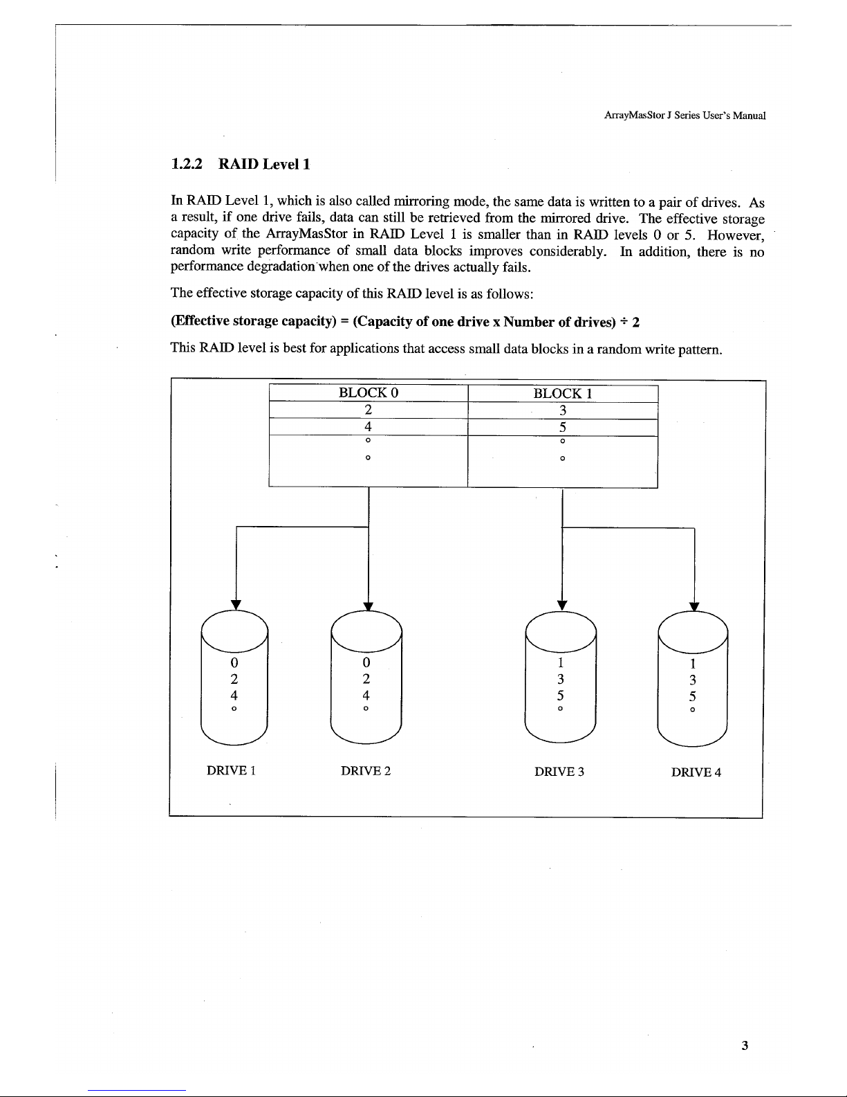
1.2 About RAID levels
The ArrayMasStor J Series supports three RAID levels, so you can choose the optimal level for your
application. The default setting is RAID Level 5 if at least 3 hard disk drives are online. The default
setting is RAID Level 1 if 2 hard disk drives are online. In the following examples, four drives are
assumed to be online.
IMPORTANT !
All stored data will be erased when the RAID level is
changed. Back-up the data before changing the RAID level.
1.2.1 RAID Level 0
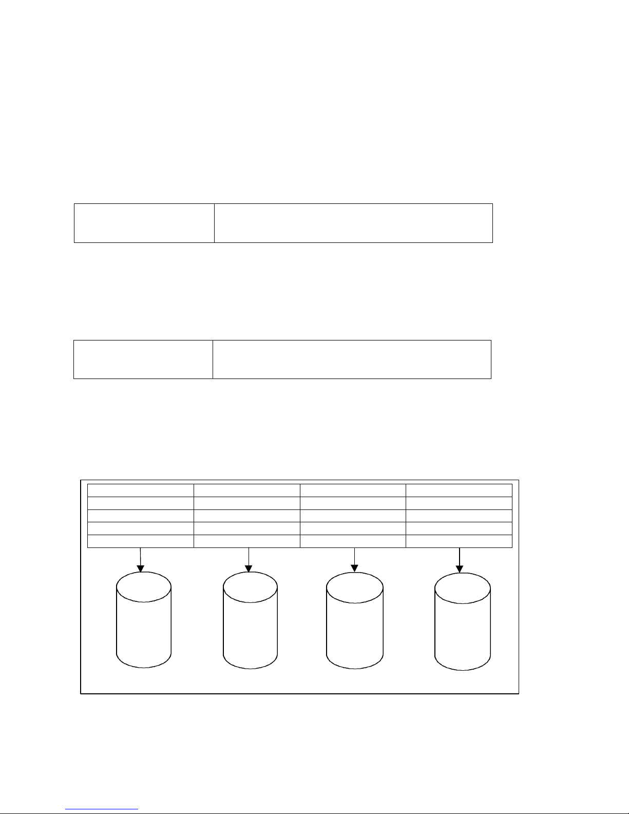
In this level, data is striped over all of the drives in the array. This provides the maximum storage
capacity, since the entire array is used solely for data storage, and the ArrayMasStor’s input/output
performance is maximized because of the drives’ parallel processing ability.
IMPORTANT !
In RAID Level 0, there is no data redundancy. Data will be
lost if a drive fails.
The effective storage capacity of this RAID level is as follows:
(Effective storage capacity) = (Capacity of one drive) x (Number of drives)
This RAID level is suitable for applications that require high performance and the largest available
storage capacity, without the need for data protection.
BLOCK 0 BLOCK 1 BLOCK 2 BLOCK 3
4 5 6 7
8 9 10 11
12 13 14 15
16 17 18 19
DRIVE 1 DRIVE 2 DRIVE 3 DRIVE 4
0
4
8
1
5
9
2
6
10
3
7
11
Page 12
Page 13
Advanced Technology and Systems Co., Ltd.
4
1.2.3 RAID Level 5
In RAID Level 5, parity data is generated and stored on the equivalent of one drive. If one drive fails,
the lost data can be reconstructed using data recorded on the other drives and the parity data. Parity
data is written on all of the drives in order to avoid performance degradation due to the intensive
access requirements that would result from using a single or specific parity drive.
The effective storage capacity of this RAID level is as follows:
(Effective storage capacity) = (Capacity of one drive) x (Number of drives - 1)
This RAID level is most appropriate when data protection is the primary consideration.
BLOCK 0 BLOCK 1 BLOCK 2 PARITY 0 - 2
3 4 5 PARITY 3 - 5
6 7 8 PARITY 6 - 8
°
°
°
°
°
°
°
°
BLOCK 0 BLOCK 1 BLOCK 2 PARITY 0-2
4 5 PARITY 3-5 3
8 PARITY 6-8 6 7
°
°
°
°
°
°
°
°
°
°
°
°
°
°
°
°
DRIVE 1 DRIVE 2 DRIVE 3 DRIVE 4
0
4
8
°
1
5
P
°
2
P
6
°
P
3
7
°
Page 14
ArrayMasStor J Series User’s Manual
5
1.3 Mixed RAID Levels
The ArrayMasStor supports mixed RAID levels. This means that the ArrayMasStor can be
configured to handle multiple logical units (LU), and that a different RAID level can be assigned to
each LU. The ArrayMasStor can support up to seven separate LU (0 – 6) and separate RAID levels.
A sample configuration is shown below:
LUN DESIGNATION HOST CONFIGURATION
LUN 0 - RAID 0
LUN 1 - RAID 1
LUN 2 - RAID 5
LUN 3 - RAID 0
LUN 3
LUN 2
LUN 1
LUN 0
LUN 3
LUN 2
LUN 1
LUN 0
LUN 3
LUN 2
LUN 1
LUN 0
LUN 3
LUN 2
LUN 1
LUN 0
Page 15
Advanced Technology and Systems Co., Ltd.
6
PHYSICAL DRIVE 1 2 3 4
LOGICAL DRIVE 1 2 3 SPARE
1.4 Hot Spare Feature
When the hot spare feature is activated, background data recovery onto the spare drive starts
immediately after the failure of an on-line drive. This feature reduces the effective storage capacity of
the ArrayMasStor, since one drive is reserved as a hot spare. However, the hot spare feature improves
the ArrayMasStor’s reliability and its ability to protect data. After the data recovery process is
complete, the ArrayMasStor is redundant (fault tolerant) again.
In the following example, there are four drives in the ArrayMasStor. The hot spare feature is only
available when more than three drives are used.
When one of the on-line drives fails, the data recorded on the failed drive is re-generated and written
onto the spare drive. After the data recovery process is complete, the spare drive takes the place of
failed drive. For example, if drive #3 fails, the hot spare drive (physical drive #4) becomes logical
drive #3.
When the failed drive is replaced, the replacement drive becomes the spare drive.
PHYSICAL DRIVE 1 2 3 4
LOGICAL DRIVE 1 2 SPARE 3
Page 16

ArrayMasStor J Series User’s Manual
7
1.5 Write Back Cache Function
When used in RAID Level 5, the write operation for small data blocks causes a data bottleneck. This
is because, before it can write the new data, the ArrayMasStor must read the old data and parity,
which are needed to generate the new parity5. This phenomenon, which is called the write penalty,
impairs performance when the host computer accesses the ArrayMasStor in a random write pattern.
The ArrayMasStor uses a large buffer as a write-back cache to compensate for the write penalty
problem. When data is acquired into the cache buffer by a ‘write’ command issued by the host
computer, the ArrayMasStor returns a ‘complete’ command to the host computer. The ArrayMasStor
gathers the small amounts of write data to the cache buffer and writes this data onto the drives at one
time.
When shutting down the ArrayMasStor using the power switch on the front panel, the ArrayMasStor‘s
firmware detects the power switch status, flushes the data in the cache to the drives, and then turns off
the power. When powering down from the AC line, a ‘synchronize cache’ command must be sent
from the host computer to the ArrayMasStor before the power is turned off. Failure to use the
‘synchronize cache’ command can result in data loss.
IMPORTANT !
Push Power Switch to turn off except for emergency. Turning
off by pulling out Power Line Cord may cause data loss in the
cache buffer.
Plugging AC power cord can’t be POWER-ON condition of ArrayMasStor J series.
IMPORTANT !
It is strongly recommended that an interruptible power
supply (UPS) be used to avoid data loss when the power
line is unstable and power outrage happens.
5
This is called “Read Modify Write”.
Page 17
Advanced Technology and Systems Co., Ltd.
8
1.6 Dynamic Data Reallocation
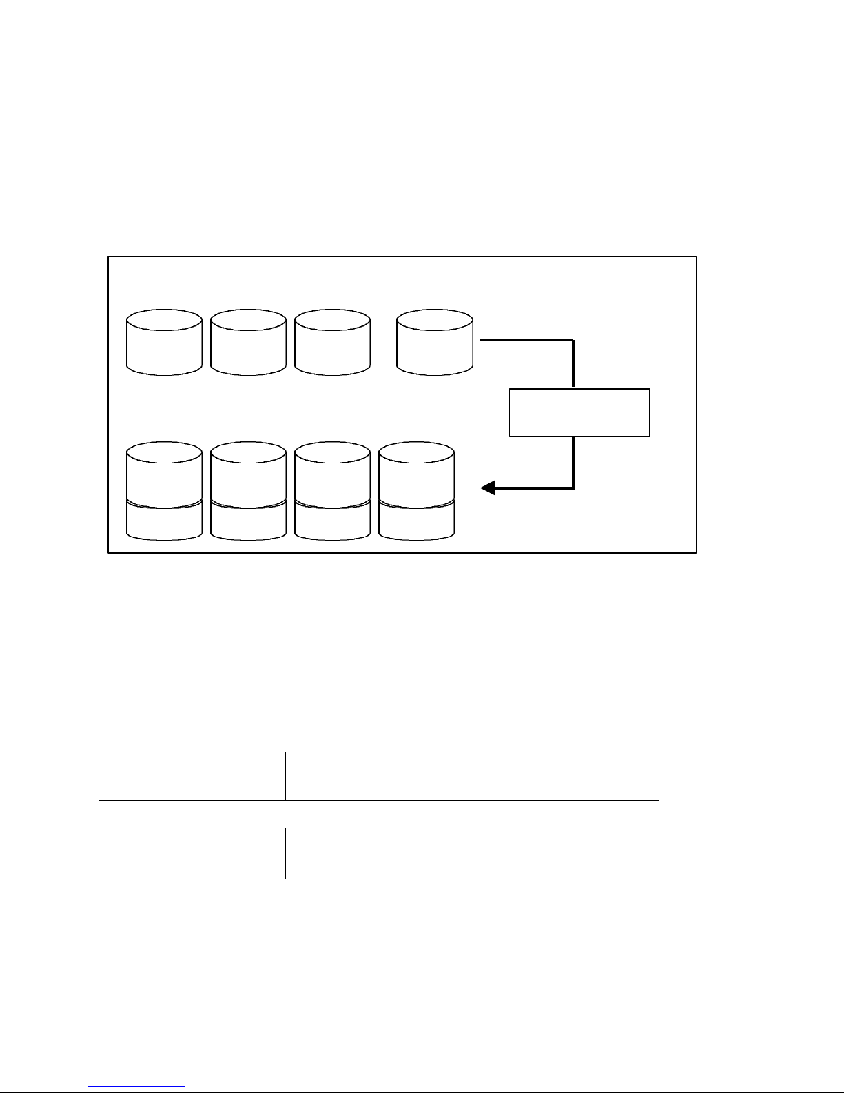
The ArrayMasStor J Series supports dynamic data reallocation, which allows the expansion of the
ArrayMasStor’s capacity by adding new drives without data loss. The additional storage capacity is
assigned a new LUN.
The original data is reallocated to suitable locations, and the parity data (for RAID Level 5) is
automatically regenerated. For RAID Level 1, the mirror data is written alongside the original data
and the original drive information is re-striped over the new drives. RAID Level 0 also offers this
feature, but there is no data redundancy when the re-stripping or reallocation procedure is executed.
Increasing the number of drives allows the same total storage capacity to be accessed faster, because
four (rather than three) drives are concurrently accessing the 40 MB of data in each LUN. Each new
LUN is treated as an individual drive by the host computer, and is easily configured from the
operating system for immediate use.
IMPORTANT !
It is strongly recommended that the surface verification
check implement before dynamic data reallocation.
IMPORTANT !
ArrayMasStor won’t permit to access from the host computer
while carrying out dynamic data reallocation.
CURRENT CONFIGURATION NEW DRIVE
NEW CONFIGURATION
LUN 0 LUN 0 LUN 0
LUN 1
LUN 0
LUN 1
LUN 0
LUN 1
LUN 0
LUN 1
LUN 0
REALLOCATION
PROCEDURE
Page 18
ArrayMasStor J Series User’s Manual
9
2 Naming Convention
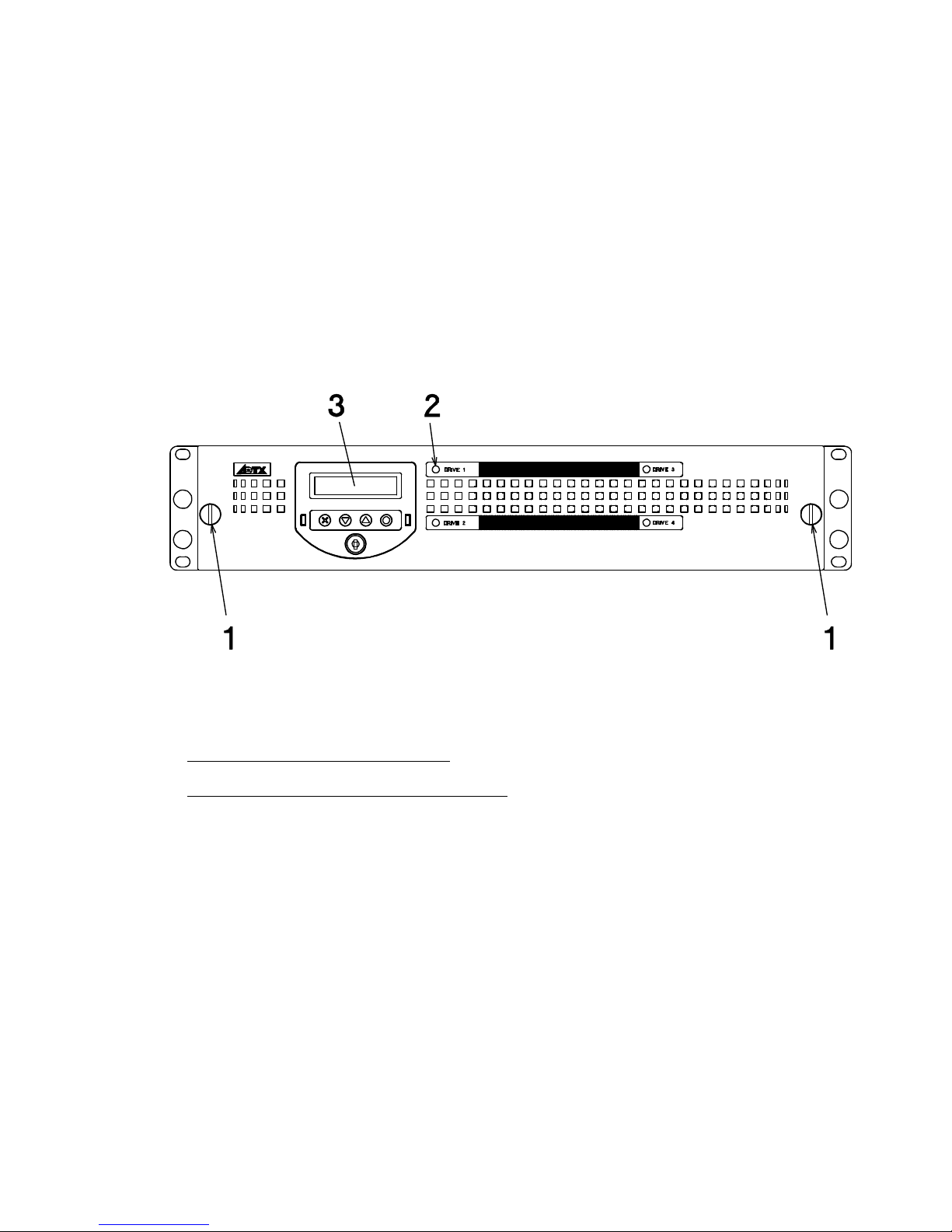
2.1 Front view
Front cover (rackmount type)
1. Screw for Front Cover
2. Drive Access/Status LED
3. Display Panel
Page 19
Advanced Technology and Systems Co., Ltd.
10
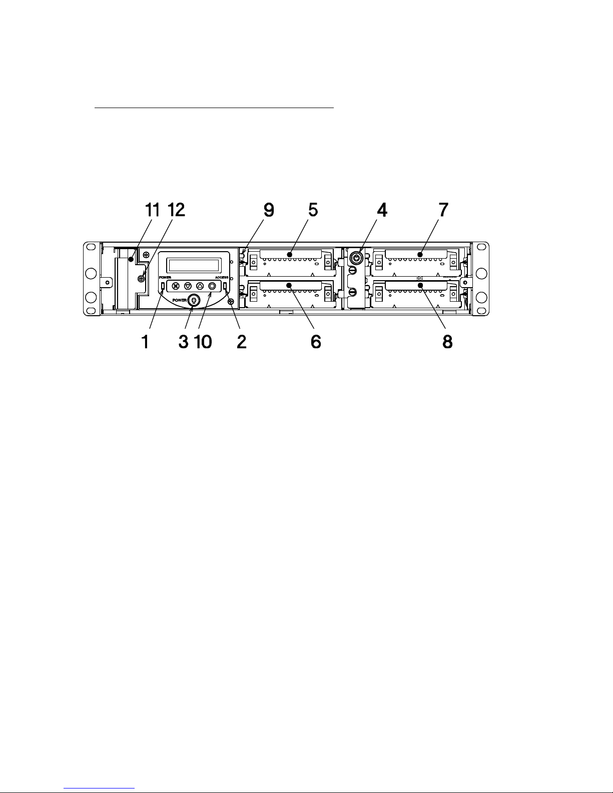
Removal of Front cover (rackmount type)
1. Power LED
2. Host Access LED
3. Power switch
4. Drive lock
5. Drive unit #1
6. Drive unit #2
7. Drive unit #3
8. Drive unit #4
9. Drive access LED
10. Operation buttons
11. Fan Module
12. Fan module screw
Page 20
ArrayMasStor J Series User’s Manual
11
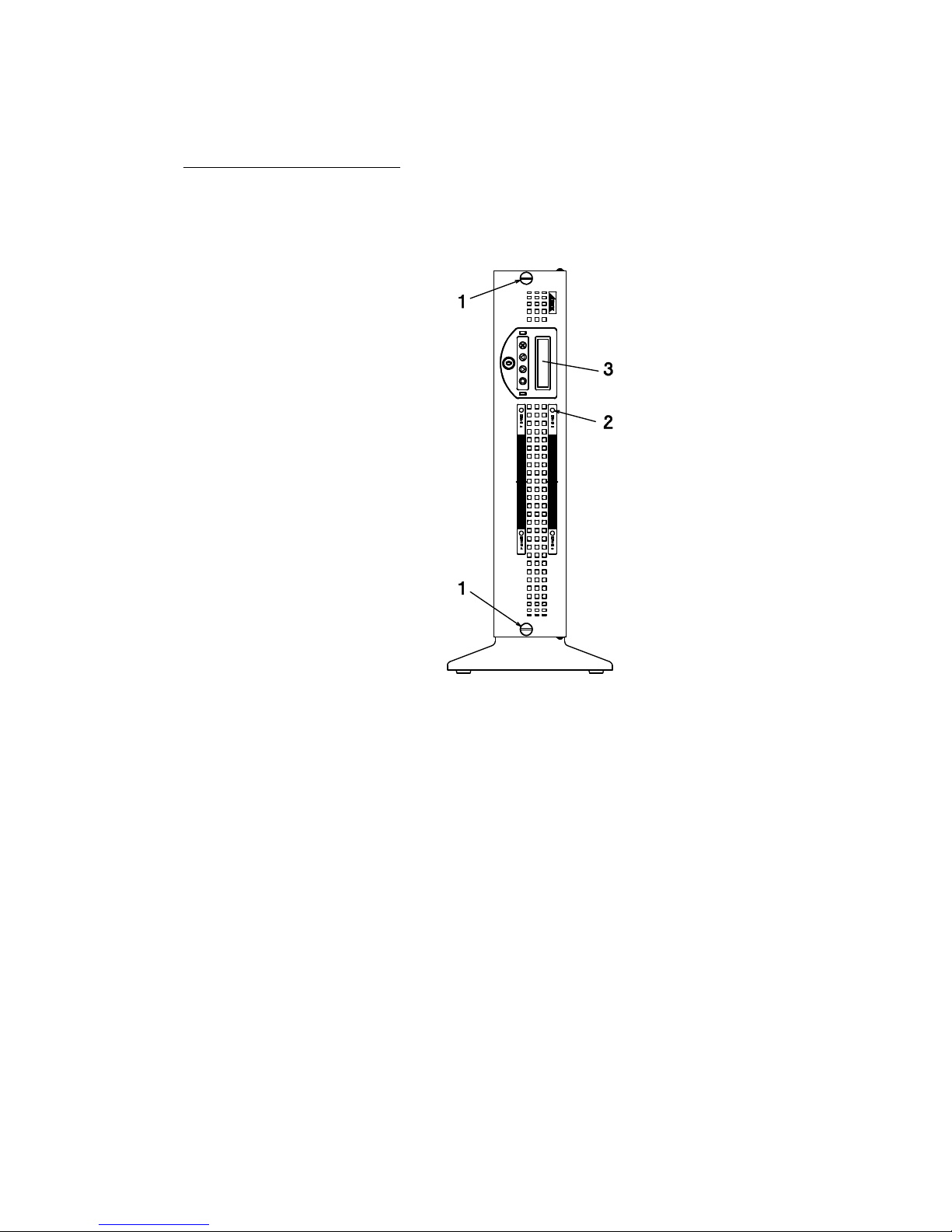
Front cover (tower type)
1. Screw for Front Cover
2. Drive Access/Status LED
3. Display Panel
Page 21
Advanced Technology and Systems Co., Ltd.
12
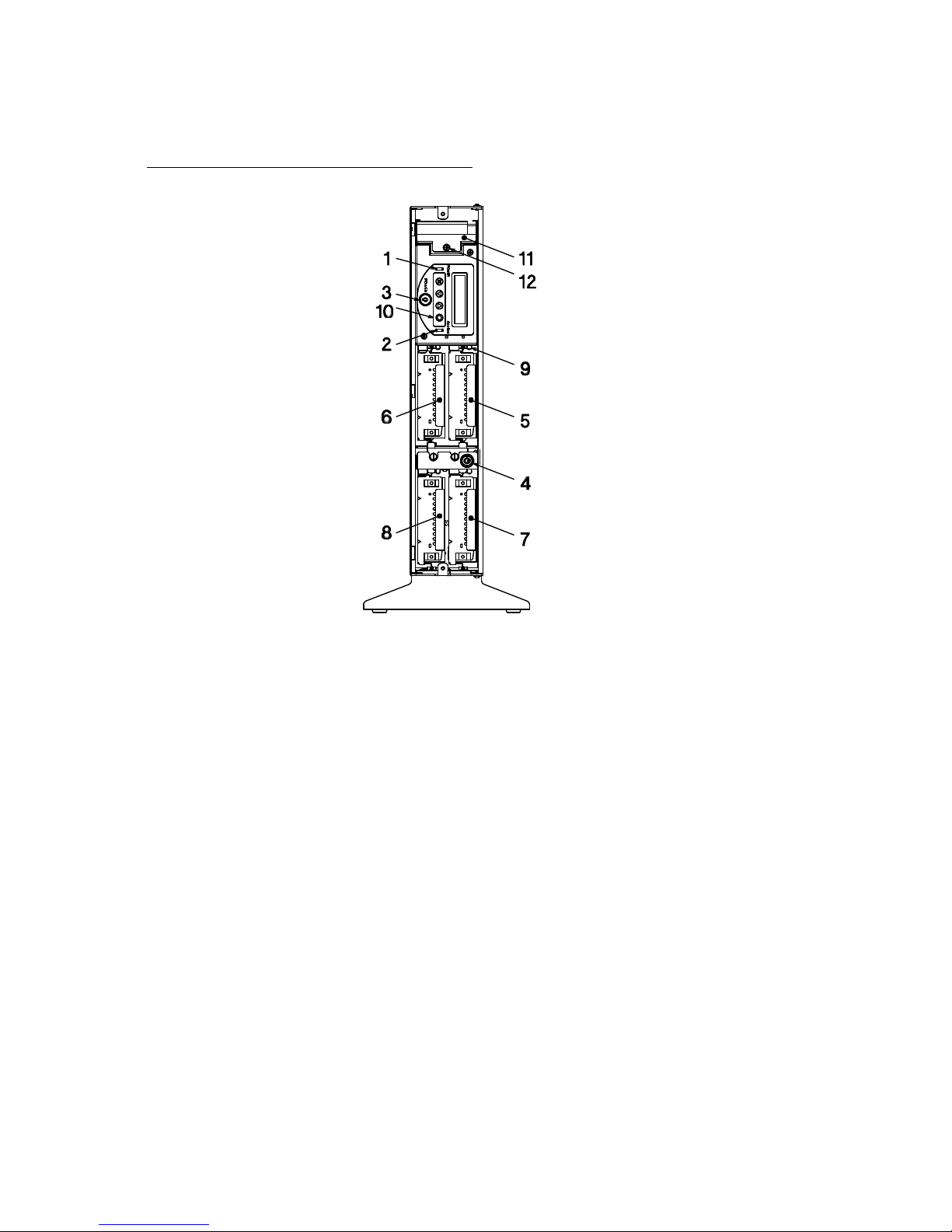
Removal of Front cover (tower type)
1. Power LED
2. Host Access LED
3. Power switch
4. Drive lock
5. Drive unit #1
6. Drive unit #2
7. Drive unit #3
8. Drive unit #4
9. Drive access LED
10. Operation buttons
11. Fan Module
12. Fan module screw
Page 22
ArrayMasStor J Series User’s Manual
13
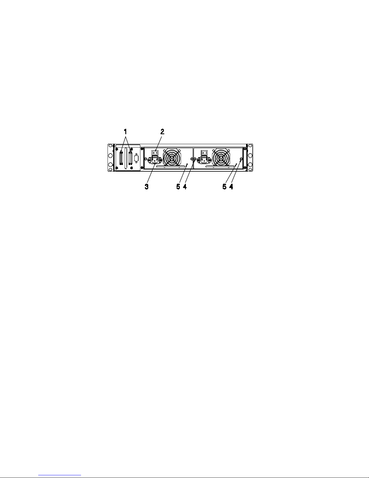
2.2 Rear view
rackmount type
1. SCSI connector (Dual channel, 68 pins, VHDCI connector)
2. Power supply switch: Normal “ON” (“I” is pressed in)
3. Power cord receptacle
4. Power Module screw
5. Power supply status indicator
Page 23
Advanced Technology and Systems Co., Ltd.
14
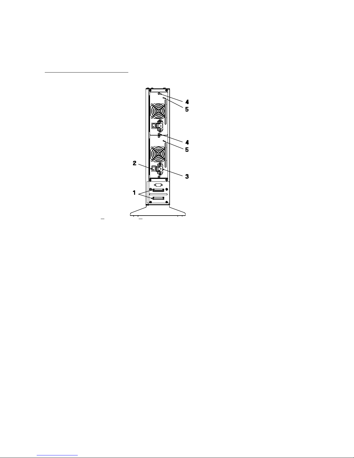
Rear View (tower type )
1. SCSI connector (Dual channel, 68 pins, VHDCI connector)
2. Power supply switch: Normal “ON” (“I” is pressed in)
3. Power cord receptacle
4. Power Module screw
5. Power supply status indicator
Page 24
ArrayMasStor J Series User’s Manual
15
3 Installing the ArrayMasStor J Series
First, position the ArrayMasStor J series in stable manner and attach the supplied Front cover.
Then, follow these instructions to connect the ArrayMasStor to a host computer.
Default settings are listed in Appendix C.
CAUTION
Never carry the ArrayMasStor with holding the Front cover
or the handle of Drive unit.
CAUTION
Be sure to attach the Front cover and to let it closed.
3.1 Connecting the Power Line Cord
Plug the supplied AC power cord to the receptacle and outlet. The ArrayMasStor uses a
100V~240VAC universal power supply with automatic voltage detection.
CAUTION
Simply plugging the AC power cord will not mean that the
ArrayMasStor is in POWER-ON condition.
3.2 Connecting the SCSI Cable
Use a SCSI cable, meeting SCSI-2 or SCSI-3 specifications , to connect the ArrayMasStor to the host
computer’s SCSI interface. If the ArrayMasStor is located at the end of the SCSI bus, attach a SCSI
terminator to the unused SCSI connectors on the back of the ArrayMasStor.
IMPORTANT !
For optimum performance, the total length of the SCSI
bus should be as short as possible. For a single-ended
SCSI card, the total cable length must be less than 1.5 m.
3.3 Turning the Power On
Turn the power switch key clockwise to power on the ArrayMasStor. Before switching on the power,
check that all drive units are inserted firmly. Switch on the ArrayMasStor before turning on the host
computer.
Page 25

Advanced Technology and Systems Co., Ltd.
16
3.4 Setting the Password
The ArrayMasStor has a default password that is used to change the configuration (see Appendix C).
The procedure for changing the password can be found in section 4.9.1., Entering the Password.
3.5 Setting the Time & Date
The clock values in the configuration menu are set to a default value. To change the clock value, use
the CHANGE CONFIG menu and follow the procedure in section 4.8.2, Changing the Date and Time
Setting. Before using the ArrayMasStor, set the internal clock to the local time. The correct local
time is required for proper operation of the background surface verify function.
3.6 Setting the SCSI ID
The SCSI ID should be set before starting the host computer. See section 4.8.3, Changing the SCSI
ID for information about changing the SCSI ID. The ArrayMasStor must be restarted before changes
to the SCSI ID will take effect.
3.7 Setting the Spare Mode and Reconfiguring the LUN
All data will be erased when the spare mode or the LUN settings are changed. As a result, changes to
these settings must be made before creating partitions or formatting the storage area. For information
about setting the spare mode, see section 4.10.1, Add Drive as Hot Spare Drive. After setting the
spare mode and the LUN configuration, restart the ArrayMasStor. The new settings will take effect
after the initialization process is completed.
The spare mode does not need to be set if the default settings are used.
3.8 Formatting
Before using, the ArrayMasStor must be partitioned or formatted so that they will work with the host
computer’s operating system. Partitioning and formatting instructions can be found in your operating
system manuals. In some cases, BIOS, file systems, or operating systems place limitations on the
capacity of a single partition. If this occurs, divide the usable area of the ArrayMasStor into partitions
that conform to the capacity limitations. In general, the format operation provided by some of device
drivers and diagnostic programs is not needed in order to be able to use the ArrayMasStor.
3.9 Connection to a Macintosh
6
The following limitations apply when connecting the ArrayMasStor to a Macintosh computer:
• Supported Machines
CPU : 68040 or Power PC
6
Macintosh is a trademark of Apple Computer, Inc.
Page 26
ArrayMasStor J Series User’s Manual
17
OS : System 7.1 or above
• The drive formatter provided with Apple computers only recognizes drives supplied by Apple
Computer. In order to format the ArrayMasStor for use with a Macintosh, a hard disk formatter
from a third party is necessary. The Hard Disk Tool kit by FWB is recommended.
• The ArrayMasStor does not support blind transfer. Please set the transfer mode to non-blind
transfer.
• Each partition has a maximum capacity of 2GB on a system 7.0 and 4GB on a system 7.5. If the
ArrayMasStor’s capacity exceeds these limitations, the entire storage capacity should be divided
into several smaller partitions.
3.10 Connection to the UNIX Systems
• The UNIX C/H/S mode must be set before the ArrayMasStor is connected to the following
operating systems:
Solaris (SPARC) 2.X
IRIX 5.X
• The configuration file in Sun OS (Solaris 2.5.1/2.6) must be edited to use the LUN.
Example (To set two LUNs to the ArrayMasStor J Series at SCSI ID 0)
SPARC station5 Turbo 170M
File name to edit : /kernel/dev/sd.conf
Before Edit After Edit
name=”sd” class=”scsi” name=”sd” class=”scsi’
target=0 lun=0; target=0 lun=0;
:
name=”sd” class=”scsi”
:
target=0 lun=1;
: :
name=”sd” class=”scsi” name=”sd” class=”scsi”
target=15 lun=0; target=15 lun=0;
PC-AT (for Intel) Adaptec AHA-2940UW
filename to edit : /kernel/dev/cmdk.conf
Before Edit After Edit
name=”cmdk” class=”scsi” name=”cmdk” class=”scsi”
target=0 lun=0; target=0 lun=0;
:
name=”cmdk”
class=”scsi”
:
target=0 lun=1;
: :
name=”cmdk” class=”scsi” name=”cmdk” class=”scsi”
target=15 lun=0; target=15 lun=0;
After editing the configuration file, re-boot the system with the boot option “-r”.
If the file is change correctly, the new LUN will appear on the ArrayMasStor’s display when
it is restarted.
Page 27

Advanced Technology and Systems Co., Ltd.
18
4 ArrayMasStor J Series Operations
The ArrayMasStor‘s status is displayed on the operation panel. By selecting menus using the
operation buttons, you can review the ArrayMasStor’s status information, or make changes to the
ArrayMasStor’s configuration.
4.1 Operation Buttons
There are four operation buttons. The up and down buttons scroll from one menu item to the next.
The select button is used to activate the menu item shown on the display. The Cancel button returns
the display to the previous menu.
Cancel Down Up Select
Page 28
ArrayMasStor J Series User’s Manual
19
4.2 Status Display (Main Menu)
4.2.1 Normal Mode
When the ArrayMasStor is functioning normally, the SCSI ID, RAID level and the ArrayMasStor’s
capacity are displayed. To change the menu, press the up or down button. Press the select button to
choose a menu item.
LCD DISPLAY EXPLANATION
This message indicates that the ArrayMasStor is operating normally.
The message shows the RAID Level and total storage capacity for the
ArrayMasStor, assuming the use of a single-LUN configuration.
The message shows the logical unit number, the RAID Level and the
total storage capacity for the ArrayMasStor, assuming the use of a
multi-LUN configuration.
Selecting this option displays the ArrayMasStor’s SCSI ID. The first
number indicates SCSI ID of channel 1 while the latter number
indicates SCSI ID of channel 2.
This option accesses the configuration window, which displays the
current settings for the number of online drives; spare drives; buzzer;
auto reconstruction mode; write cache; AIX error notice mode;
UNIX C/H/S mode; ultra SCSI mode; initiator mode; periodic check;
and DPO/FUA bit.
This option accesses the system status window, which displays the
current system status; serial number; microcode level; system status
code; current system time; and current system calendar status.
This option displays information about the drives connected to the
ArrayMasStor.
This option changes the ArrayMasStor’s current configuration, after
the correct password has been entered. The following settings can be
changed: SCSI ID; RAID level; reconfigure; buzzer mode; auto
reconstruction mode; AIX error notice; UNIX C/H/S mode; Write
Cache mode; ultra SCSI mode; UPS mode; initiator mode; surface
check; periodic check; DPO/FUA bit; buzzer test; password; error
insertion; system trace; clear system trace; and change time.
RAID SUBSYSTEM
- RAID5 XX . X GB
OR
RAID SUBSYSTEM
- 0 RAID5 XX . X GB
RAID SUBSYSTEM
-SCSI ID 0/0
RAID SUBSYSTEM
-CONFIGURATION
RAID SUBSYSTEM
-SYSTEM STATUS
RAID SUBSYSTEM
-CHANGE CONFIG
RAID SUBSYSTEM
-DRIVE STATUS
Page 29
Advanced Technology and Systems Co., Ltd.
20
4.2.2 Degraded Mode (drive failure)
When a drive fails, the physical number of the defective drive is displayed on the operation panel and
the status indicator next to the failed drive turns red. If the buzzer is switched on, it will beep. If a
drive fails, it should be replaced as soon as possible.
This display indicates that the subsystem is in degraded mode, which
means that one of the drives has failed. When the buzzer mode is
switched on, the buzzer beeps and STOP BUZZER appears on the
display.
To turn the buzzer off, press the select button. When the buzzer
mode is off, this is replaced by the DRIVE n FAIL display as shown
in the next figure.
This is the final display for degraded mode.
If a spare drive fails, the system goes to degraded mode, the drive
number is displayed.
If a data drive and a spare drive fail simultaneously, the drive
numbers are displayed, where n is the main drive and m is the spare
drive.
DEGRADED MODE
-STOP BUZZER
DEGRADED MODE
DRIVE n FAIL
DEGRADED MODE
PRESS 0 OR X
DEGRADED MODE
DRIVE n(m) FAIL
DEGRADED MODE
SPARE n FAIL
Page 30
ArrayMasStor J Series User’s Manual
21
RAID SUBSYSTEM
SPARE n FAIL
RECONSTRUCTION
DRIVE X n%
4.2.3 Drive Replacement
When auto reconstruction mode is turned on, data reconstruction starts automatically after a failed
drive is replaced. When auto reconstruction mode is turned off, a menu to start reconstruction is
displayed after the failed drive is replaced, and data reconstruction must be initiated manually. The
following example assumes that a drive has failed and auto reconstruction mode is turned off.
The display indicates that the failed drive has been replaced. Press
the select button to start data reconstruction.
To confirm the start of data reconstruction, press the select button.
If the cancel button is pressed, the display returns to the main menu
without starting reconstruction.
Press the select button to confirm.
The display indicates that data reconstruction has started, and
indicates the drive that is being reconstructed, and the progress (in
percent) of the reconstruction process. When data reconstruction is
complete, the display returns to the main menu.
The display indicates that reconstruction has finished with spare
drive configuration. After the failed spare drive is being replaced, the
display returns to the main menu.
4.2.4 Data Reconstruction
The target drive for data reconstruction and progress (in percent) of
the reconstruction are displayed.
DEGRADED MODE
-START RECON
RECONSTRUCTION
O TO START OR X
RECON STARTED
PRESS O
RAID SUBSYSTEM
DRIVE X n%
Page 31
Advanced Technology and Systems Co., Ltd.
22
4.2.5 Data Initialization
When the RAID level or spare drive settings are changed, data initialization is necessary to ensure the
consistency of the parity or mirror data. After changing the RAID level or spare drive settings, the
ArrayMasStor should be turned off. After restarting the ArrayMasStor, data initialization starts
automatically. Another method to start data initialization is to select the INITIALIZE option from the
operation panel after the ArrayMasStor fails. The time required for data initialization depends on the
configuration and storage capacity of the ArrayMasStor.
During the data initialization, the progress (in percent) is displayed.
When initialization is in progress, the ArrayMasStor will not accept
SCSI commands from the host computer.
When data initialization is complete, the operation panel returns to
the main menu and the ArrayMasStor accepts SCSI commands from
the host computer.
4.2.6 Data Reallocation
During dynamic data reallocation, the progress (in percent) is
displayed. When dynamic data reallocation is in progress, the
ArrayMasStor will not accept SCSI commands from the host
computer.
INITIALIZATION
DATA n%
RAID SUBSYSTEM
-RAID5 XXGB
REALLOCATION
LUN0 n%
Page 32
ArrayMasStor J Series User’s Manual
23
4.2.7 Double Fault (Failure of two or more drives)
When two or more drives fail, data stored on the ArrayMasStor cannot be reconstructed and some or
all of the data will be permanently lost. To avoid double fault, failed drives should be replaced as
soon as possible.
There are two ways to return to the normal mode.
a) Replace only the first failed drive by following the procedures in section 4.2.8, Forced Data
Reconstruction.
b) During system halt, replace the failed drives by following the procedures in section 4.2.9, System
Halt.
The display indicates that the ArrayMasStor is in degraded mode 2,
which means that two or more drives have failed.
This menu turns off the buzzer. Pressing the select button advances
the display to the stop buzzer menu.
The display indicates the physical numbers of the failed drives.
IMPORTANT !
When two or more drives fail, some or all of the data will be
erased. If a drive fails, replace it as soon as possible
DEGRADED MODE-2
DRIVE 1 2 FAIL
RAID SUBSYSTEM
DEGRADED MODE-2
DEGRADED MODE-2
-STOP BUZZER
Page 33
Advanced Technology and Systems Co., Ltd.
24
4.2.8 Forced Data Reconstruction
Normally, when two drives fail, it is necessary to save the remaining data onto back-up media (e.g.
tape) and replace the failed drives. If back-up media are unavailable, the ArrayMasStor allows users
to perform forced data reconstruction. During forced data reconstruction, the ArrayMasStor detects
the unrecoverable read errors in the source drives, skips the damaged sector and continues to
reconstruct from the next sector, until the last sector has been reconstructed. The data in the sector or
sectors with unrecoverable errors are either damaged or lost.
When two drives fail, DRIVE X Y FAIL appears on LCD display, where X is the physical number of
the first failed drive. Replace the first failed drive (X) before replacing the second failed drive (Y).
(Note: If the second failed drive (Y) is replaced before the first failed drive (X), the ArrayMasStor
enters system halt mode and the host computer cannot access the data in the ArrayMasStor. If this
happens, swap drives X and Y and then restart the ArrayMasStor.)
After replacing the first failed drive, FORCE RECON appears on the display. This menu appears
when the source drive failed during normal reconstruction mode, without replacement of the first
failed drive. Press the select button to start forced data reconstruction. When the data reconstruction
is complete, the ArrayMasStor enters degrade mode (when only one failed drive is left), or degrade
mode-2 (when more than one failed drives are left), except spare drive.
The display indicates that two drives have failed. Replace the first
failed drive (x), before replacing the second failed drive (y).
The display indicates that the first failed drive has been replaced.
Press the select button to start forced data reconstruction.
Press the select button again to confirm the start of force data
reconstruction. If the cancel button is pressed, the display returns to
the main menu and reconstruction is cancelled.
Press the select button again to confirm the start of forced data
reconstruction.
The display indicates the forced data reconstruction has started, and
indicates the drive that is being reconstructed, and the progress (in
percent) of the reconstruction process. When forced data
reconstruction is complete, the display returns to degraded mode or
degraded mode-2 menu.
RECONSTRUCTION
O TO START OR X
DEGRADED MODE-2
DRIVE x y FAIL
DEGRADED MODE-2
-FORCE RECON
RECON STARTED
PRESS O
RECONSTRUCTION
DRIVE x n%
Page 34
ArrayMasStor J Series User’s Manual
25
4.2.9 System Halt
When an unrecoverable error occurs (due to the replacement of two or more drives, or to the failure of
the RAID controller board), the ArrayMasStor enters system halt mode. In system halt mode, the
ArrayMasStor prevents further data corruption by rejecting SCSI commands from host computer. If a
system halt occurs for reasons other than those stated above, contact your service representative for
assistance.
IMPORTANT !
During initialization all user data is erased.
The display indicates that the ArrayMasStor has entered system halt.
If the buzzer is switched on, it will beep. To stop the buzzer, press
the select button.
To turn off the buzzer, press the select button again. If the cancel
button is pressed, the display returns to the previous menu without
turning off the buzzer.
Initialization erases all error information on the drives and returns
the system to normal mode. However, during initialization all data
is erased.
A password is necessary to start initialization. For instruction on
how to enter the password, see section 4.9.1, Entering the Password.
Press the cancel button to return the display to the previous menu.
Press the select button again to confirm. Press the cancel button to
return the display to the previous menu and abort the initialization
process.
SYSTEM HALT
-INITIALIZE
RAID SUBSYSTEM
-STOP BUZZER
STOP BUZZER
PRESS O OR X
PASSWORD
****
INITIALIZE
O TO START OR X
Page 35
Advanced Technology and Systems Co., Ltd.
26
4.2.10 Fan Failure
The ArrayMasStor is equipped with two fans that dissipate the heat generated by the drives. Without
these fans, the drive may fail due to lack of ventilation. If the fan fails, contact your service
representative for assistance.
The display indicates that the fan has failed. If the buzzer is
switched on, it will beep. To stop the buzzer, press the select
button.
To turn off the buzzer, press the select button again. If the cancel
button is pressed, the display returns to the previous menu without
turning off the buzzer.
The display returns to the main menu, the FAN FAIL appears,
along with the ArrayMasStor’s RAID level and total storage
capacity.
FAN FAIL
-STOP BUZZER
STOP BUZZER
PRESS O OR X
FAN FAIL
RAID 5 27GB
Page 36
ArrayMasStor J Series User’s Manual
27
4.2.11 Power Supply Failure
The ArrayMasStor is equipped with a dual power supply.
The “PWR SUPPLY FAIL” message will be displayed on the display panel if one of the power supply
modules failed.
Make sure of the following items below if this message is displayed.
(1) The two(2) main switch of the power supply module located on the rear side are turned “ON” (“I”
is pressed in). (Refer to the drawing in section 2.2).
(2) The two(2) power cords are connected properly.
(3) The two(2) power supply modules are sealed properly.
Replace the power supply module if the three(3) items described above have been checked and the
power supply failure still occurred. Call a trained personnel if the power supply module to be replaced
is done while the machine is in operation.
Please follow the procedure described in section 5.2 to replace the power supply module with the
machine powered down.
The display indicates that the power supply has failed. If the
buzzer is switched on, it will beep. To stop the buzzer, press the
select button.
To turn off the buzzer, press the select button again. If the cancel
button is pressed, the display returns to the previous menu without
turning off the buzzer.
The display returns to the main menu, the “PWR SUPPLY
FAIL“ appears, along with the ArrayMasStor’s RAID level and
total storage capacity.
PWR SUPPLY FAIL
-STOP BUZZER
STOP BUZZER
PRESS O OR X
PWR SUPPLY FAIL
RAID 5 27GB
Page 37
Advanced Technology and Systems Co., Ltd.
28
4.2.12 Surface Check
The Surface Check function prevents a double fault from occurring when an error correcting code
(ECC) fault is encountered while the ArrayMasStor is operating in degraded mode. This function is
not available in RAID Level 0, because the data are not redundant. In RAID Levels 1 and 5, the
surface check scans the drives for ECC faults and fixes these errors by overwriting them with correct
data generated from the mirror or parity data. The ArrayMasStor uses three selectable methods to
check data:
Surface check: This scans the entire data area for ECC faults and reconstructs and overwrites errors.
Parity regeneration: In RAID Level 5, this regenerates each parity block and rewrites it to the drives.
Random Check: This scans random storage areas for ECC faults and fixes the errors.
All of these tests should be performed periodically to ensure data and parity consistency.
From the Change Configuration menu, use the up or down button to
choose the SURFACE CHECK option.
After selecting the SURFACE CHECK option, the ArrayMasStor
immediately checks the entire data storage area.
During the procedure, the progress of the scan is displayed in percent.
When the scan is complete, the display returns to the main menu.
Choose the PARITY CHECK option from the CHECK MODE menu to start
the parity regeneration process. This process begins with the surface check
procedure and is followed by the parity regeneration procedure. This option
is only available if one of the LUNs is set to RAID Level 5.
During the procedure, the progress of the scan is displayed in percent.
When the scan is complete, the display returns to the main menu.
Choosing RANDOM CHECK from the SURFACE CHECK menu
starts the random check procedure.
When random check option is selected, the start time for the check
appears on the display.
SURFACE CHECK
PROGRESS 80%
CHECK MODE
SURFACE CHECK
RAID SUBSYSTEM
SURFACE CHECK
RAID SUBSYSTEM
PARITY CHECK
RAID SUBSYSTEM
PROGRESS 80%
RAID SUBSYSTEM
RANDOM CHECK
RAID SUBSYSTEM
TIME: 2300
Page 38
ArrayMasStor J Series User’s Manual
29
RAID SUBSYSTEM
- 0 RAID5 XXGB
4.3 LUN Configuration
The LUN is shown through the Operation Panel.
The information of LUN 0 is shown on the display. Press the up or
down buttons to display other LUN information for multi-LUN
configuration case.
The information of LUN 1 is shown on the display by pressing the
down button.
4.4 CHS Information
Each LUN can be assigned to a channel or to both channels.
Case 1: LUN0 are visible to both channels;
The LUN number, RAID level, and capacity information are shown
on the display. Pressing the select button will show the CHS
information.
Press the select button to display the CHS information of LUN 0.
Case 2: LUN0 is visible to channel n only;
The LUN number, RAID level, and capacity information are shown
on the display. Pressing the select button will show the CHS
information.
Press x to return to the previous menu.
RAID SUBSYSTEM
- 1 RAID5 XXGB
RAID SUBSYSTEM
- 0 RAID5 27GB
LUN0 Ch1 & Ch2
CHS : 28086:16:63
RAID SUBSYSTEM
- 0 RAID5 27GB
LUN0 Ch n
CHS : 28086:16:63
Page 39
Advanced Technology and Systems Co., Ltd.
30
4.5 SCSI ID Information
SCSI ID information can be seen at the main menu by pressing the up
and down buttons.
4.6 Display System Configuration
From the main menu, use the up or down button to display the
configuration menu. Press the select button to choose the
configuration menu, and then use the up or down button to select the
items to be displayed.
4.6.1 Number of Drives
This displays the number of drives installed in the ArrayMasStor.
4.6.2 Hot Spare Drive
When a spare drive is installed and configured, SPARE ASSIGNED
appears. If the spare drive is not installed and configured, NO
SPARE DRIVE appears.
4.6.3 Buzzer Mode
The on/off status of the buzzer is displayed. When the buzzer is on,
it beeps when a failure occurs.
4.6.4 Automatic Reconstruction Mode
When automatic reconstruction mode is turned on, data
reconstruction starts automatically when a replacement drive is
installed. If both the hot spare drive and auto reconstruction mode
are enabled, data reconstruction on the spare drives starts
automatically after a drive fails. When automatic reconstruction
mode is turned off, after a failed drive has been replaced, DRIVE
REPLACED – START RECON appears on the display. Data
reconstruction can now be started (see section 4.2.4, Data
Reconstruction).
RAID SUBSYSTEM
-CONFIGURATION
CONFIGURATION
4 DRIVES ONLINE
CONFIGURATION
NO SPARE DRIVE
CONFIGURATION
BUZZER ON
RAID SUBSYSTEM
SCSI ID 0/0
CONFIGURATION
AUTO RECON ON
Page 40
ArrayMasStor J Series User’s Manual
31
4.6.5 Write Cache Mode
The Write Cache Mode controls the ArrayMasStor’s controller card
and drive cache. Disabling the write cache mode bypasses the drive
cache and causes data to be written directly to the drives. This
degrades the ArrayMasStor’s performance.
4.6.6 AIX Error Notice Mode
If the ArrayMasStor is used with an RS/6000 machine that uses AIX
operating system, the AIX error notice mode should be turned on.
This will allow the ArrayMasStor to receive logged data through the
AIX “errpt” command. If the ArrayMasStor is used with a non-AIX
operating system, the AIX error notice mode should be turned off.
IMPORTANT !
Turn off the AIX error notice mode when using the
ArrayMasStor with non-AIX operating system. Failure to do
so may cause the ArrayMasStor to malfunction.
4.6.7 UNIX C/H/S Mode
The UNIX C/H/S status is displayed. When the ArrayMasStor is
used with host computers using the UNIX operating system, the
C/H/S mode should be turned on.
4.6.8 Ultra SCSI Mode
When the ultra SCSI mode is turned on, a maximum data transfer rate
of 40MB/second can be achieved. If it is turned off, the maximum
transfer rate is 20MB/s.
4.6.9 Initiator Mode
When the initiator mode is turned on, the ArrayMasStor can copy its
data to another storage device, such as a SCSI drive or another
ArrayMasStor. The new storage device must have a capacity that is
equal to or greater than the ArrayMasStor’s.
4.6.10 Background Surface Check
CONFIGURATION
ERR NOTICE OFF
CONFIGURATION
UNIX C/H/S OFF
CONFIGURATION
ULTRA SCSI ON
CONFIGURATION
INITIATOR OFF
CONFIGURATION
WRITE CACHE ON
Page 41
Advanced Technology and Systems Co., Ltd.
32
When the background surface check is turned on, the ArrayMasStor
automatically performs surface checks. The default setting is on,
with checks starting at 00:00 each Sunday. The execution time is 60
minutes and, for proper operation, the ArrayMasStor’s internal clock
must be set to the correct local time.
The check interval (weekly each Sunday) is displayed. The
ArrayMasStor supports three user-selectable intervals: once, twice
and three times per week.
The start time (00:00) and execution time (60 minutes) are displayed.
4.6.11 DPO/FUA Bit
The DPO/FUA (disable page out/force unit access) is used only
when the host computer’s operating system issues the FUA
command for every read/write command. Use of this command
7
degrades the ArrayMasStor’s performance. To prevent this from
happening, the DPO/FUA bit should be turned off.
IMPORTANT !
Only turn on the DPO/FUA bit if your operating system uses
the force unit accesses command with its read and writes
operations. For additional information, see your operating
system manual.
7
When a FUA read/write command is sent to the ArrayMasStor, the cache is bypassed and the read
and write operations are sent directly to the drives. This results in impaired performance.
CONFIGURATION
PERIODIC CHK ON
CONFIGURATION
WEEKLY (SUN)
CONFIGURATION
00:00 (60 MIN)
CONFIGURATION
DPO/FUA BIT OFF
Page 42
ArrayMasStor J Series User’s Manual
33
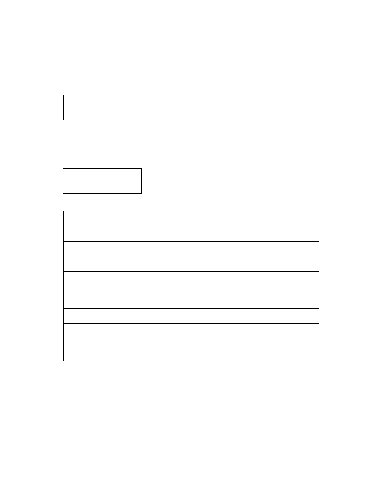
4.7 System Status
From the main menu, use the up or down button to display SYSTEM
STATUS. Then press the select button to access the system status
menu. Press the up or down button to access the following
information.
4.7.1 System Status
The system status is displayed. System status has the following
meanings.
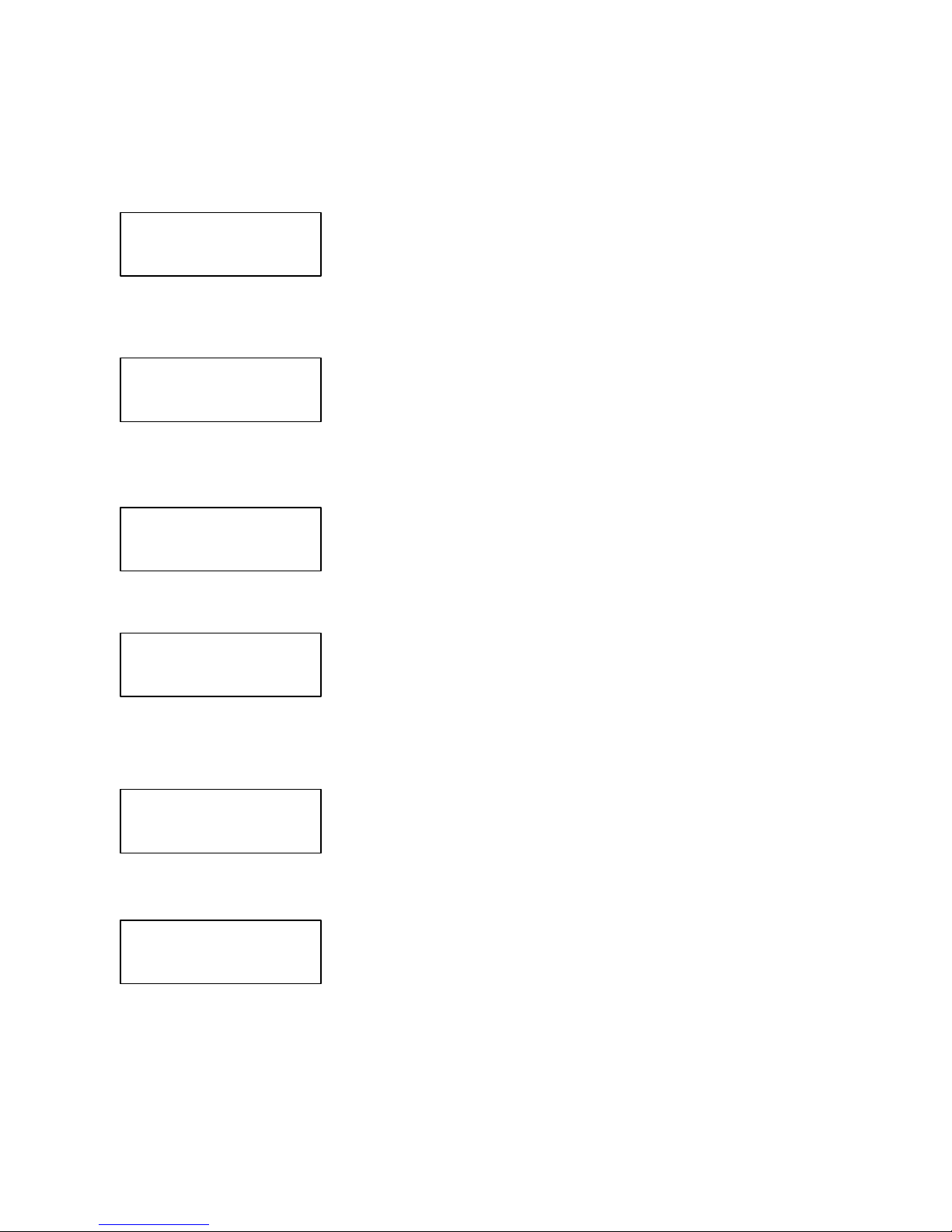
STATUS DESCRIPTION
NORMAL MODE The ArrayMasStor is operating without errors.
DEGRADED MODE One of the drives has failed. Replace the failed drive as soon as
possible.
RECONSTRUCTION Data reconstruction is in progress.
REPLACED A failed drive has been replaced. Reconstruction has not started
because the auto reconstruction mode is turned off. Use the operation
buttons to start data reconstruction.
DEGRADE MODE-2 Two or more drives have failed. Save all data onto backup media and
replace the failed drives.
RECONSTRUCTION-2 Forced data reconstruction is in progress. If a sector of the source drive
cannot be read, data reconstruction skips that sector and proceeds to
the next sector.
REALLOCATION Data reallocation is in process. In reallocation mode, ArrayMasStor
ignores commands from the host computer.
INITIALIZING Data initialization is in process because the RAID level or spare
setting has been changed. During initialization, ArrayMasStor ignores
commands from the host computer.
SYSTEM HALT Two drives have failed, an unrecoverable error has occurred or drives
have been replaced incorrectly.
RAID SUBSYSTEM
-SYSTEM STATUS
SYSTEM STATUS
XXXXXXXXXXXX
Page 43
Advanced Technology and Systems Co., Ltd.
34
4.7.2 Serial Number
The ArrayMasStor’s serial number is displayed.
4.7.3 Microcode Revision
This message shows the version number of the microcode.
4.7.4 System Status Code
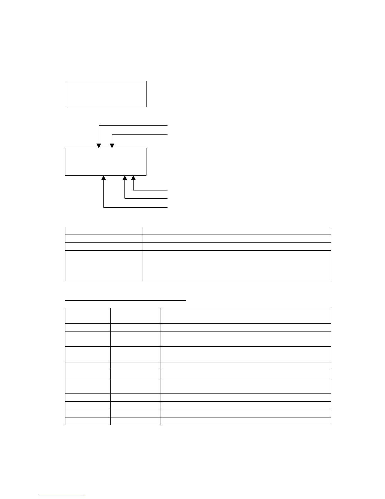
The first four digits of the system status code are displayed. For
additional information about system status codes, see section 4.7.1,
System Status.
The last four digits of the system status code are displayed.
4.7.5 System Status Time and Date
Displays the time.
Displays the day and date.
SYSTEM STATUS
S/N: XXXXXXXX
SYSTEM STATUS
MICRO: JXXX
SYSTEM STATUS
CODE: XXXXXXX
SYSTEM STATUS
MORE: XXXXXXX
SYSTEM STATUS
TIME: 10:10
SYSTEM STATUS
2001 06/30 (WED)
Page 44
ArrayMasStor J Series User’s Manual
35
4.8 Drive Status
From the main menu, use the up or down button to display DRIVE
STATUS. Then press the select button to access the drive status
menu. Press the up or down button to choose the desired drive.
Press the cancel button to return the display to the main menu.
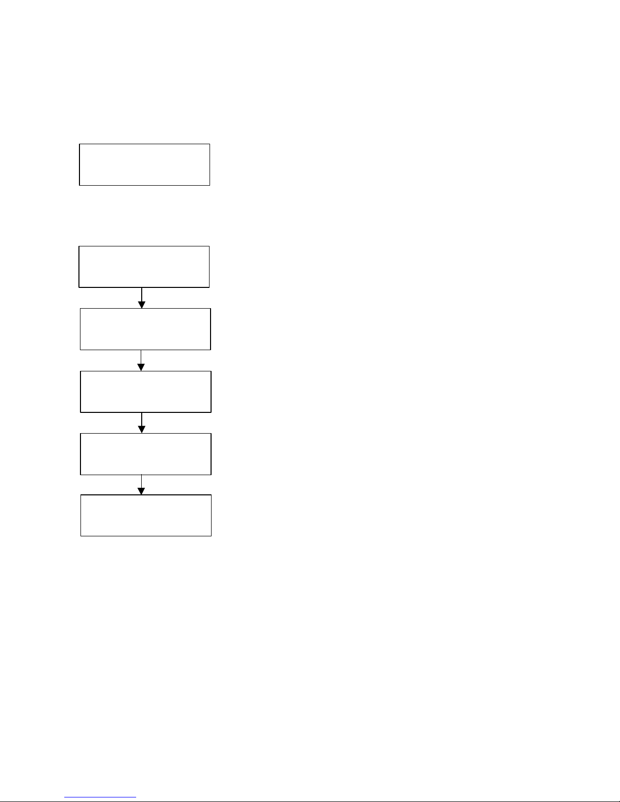
DRIVE NUMBER
DRIVE STATUS
DRIVE POWER
LOGICAL DRIVE NUMBER
DRIVE STATUS CODE
DRIVE NUMBER Physical location of the drive
DRIVE STATUS Status of the drive. (See next table for details.)
DRIVE POWER 1 means that drive is powered on. 0 means power off.
LOGICAL DRIVE
NUMBER
Usually corresponds to the physical drive number. However, after
data reconstruction on a spare drive, the logical drive numbers of the
failed and spare drives are swapped. In this case, the logical drive
number will be different from the physical number.
DRIVE STATUS AND STATUS CODE
DRIVE
STATUS
STATUS
CODE
Meaning
ON-LINE 000 The drive is operating normally.
FAIL 010 The drive has failed and should be replaced as soon as
possible.
NO DMA33 010 The drive does not support Ultra DMA 33MB. It should be
replaced with a drive that supports Ultra DMA 33MB.
Too Small 010 The drive is smaller than other drives in the ArrayMasStor.
RECONST 022 Data reconstruction is in progress.
REPLACED 002 The failed drive was replaced, but data reconstruction has not
started because auto reconstruction mode is turned off.
MISSING 011 The drive has been removed.
SPARE 300 The drive is reserved as a spare.
BLANK 101 There is no drive in this location.
EXTRA 100 A drive is installed but is not recognized by the firmware.
RAID SUBSYSTEM
-DRIVE STATUS
DRIVE n XXXXX
CODE: XXX L:n P
Page 45
Advanced Technology and Systems Co., Ltd.
36
PASSWORD CHANGED
PRESS O
4.9 Changing System Configuration
From the main menu, use the up or down button to display
CHANGE CONFIG. Press the select button to access the change
configuration menu.
4.9.1 Entering the Password
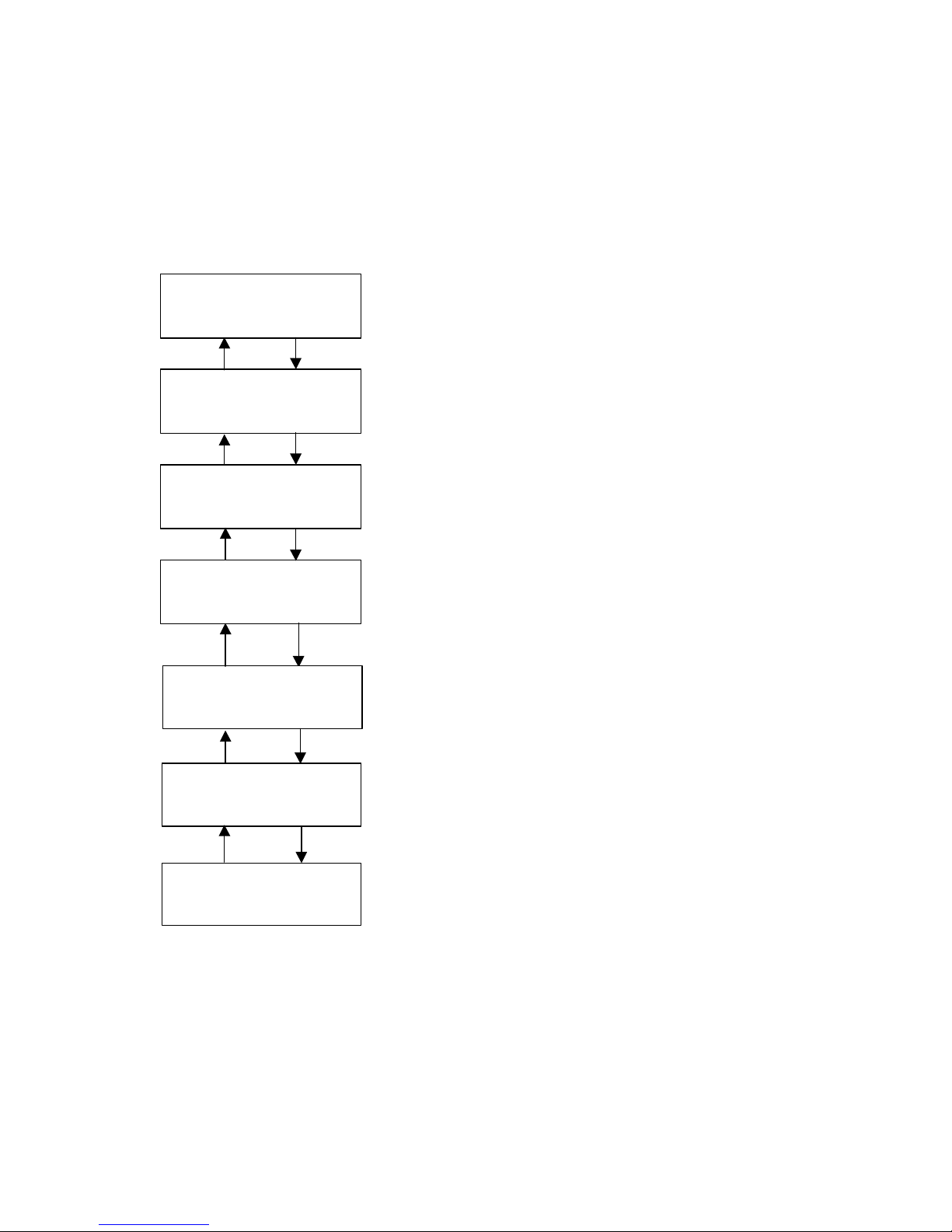
Press the select button to change the password configuration.
Use the up or down button to display the correct digit, then press the
select button to enter the digit. Repeat this procedure until all four
digits are entered. See Appendix C for the default password.
Confirm the password by entering the four-digit number.
Press the Select button to confirm.
The main menu is displayed after configuring the password.
RAID SUBSYSTEM
-CHANGE CONFIG
CHANGE CONFIG
- PASSWORD
CHANGE PASSWORD
****
CONFIRM
****
CHANGE CONFIG
- PASSWORD
Page 46
ArrayMasStor J Series User’s Manual
37
4.9.2 Changing the Date and Time Setting
The ArrayMasStor’s system clock has been set before shipment. It is usually not necessary to
reconfigure the date and time setting.
Press the select button to change the date and time setting.
Choose the parameter to be changed (date: year, month, date, day of
week; time: hour, minute) by pressing the select button.
Use the up or down button to choose a new value. Press the select
button to enter the new value.
Use the up or down button to choose a new value. Press the select
button to enter the new value.
Use the up or down button to choose a new value. Press the select
button to enter the new value.
Use the up or down button to choose a new value. Press the select
button to enter the new value.
Use the up or down button to choose a new value. Press the select
button to enter the new value. Press cancel button to return to the
change configuration menu.
CHANGE CONFIG
-DATE & TIME
YEAR
2001
MONTH
01
DATE
01
DAY OF WEEK
MONDAY
HOUR
10
MINUTE
26
Page 47
Advanced Technology and Systems Co., Ltd.
38
4.9.3 Changing the SCSI ID
From the change configuration menu, use the up or down button to
display SCSI ID. Press the select button to access the SCSI ID menu.
The SCSI ID menu is now displayed. Use the up or down button to
choose a new SCSI ID for channel 1. Press the cancel button to return
the display to the change configuration menu without changing the
SCSI ID. Press the select button again. Use the up or down button to
choose a new SCSI ID for channel 2.
Press the select button again to confirm. Press the cancel button to
return the display to change configuration menu without changing the
SCSI ID.
The new SCSI ID will take effect when the ArrayMasStor is restarted.
CHANGE CONFIG
-SCSI ID
SCSI ID
Ch1 : n Ch2 : m
Ch1 : n Ch2 : m
O OR X TO CANCEL
CHANGED RESET
OR X TO CANCEL
Page 48
ArrayMasStor J Series User’s Manual
39
4.9.4 Reconfigure
Using reconfigure, it is possible to alter the number of LUN to be configured, assign individual RAID
levels to each LUN, and set the capacity (in reference to the ArrayMasStor’s total capacity) for each
RAID Level.
IMPORTANT !
The reconfigure function will erase all of the data stored on the
ArrayMasStor. It is strongly recommended that data be
regularly backed up.
From the Change Configuration menu, use the up or down button to
display RECONFIGURE. Press the select button to access
reconfigure menu.
Reconfiguring the ArrayMasStor will start the data initialization
process, which will erase all of the data stored on the ArrayMasStor.
To confirm, press the select button. Pressing the cancel button aborts
the change.
Use the up or down button to display spare assignment.
Press the select button to assign a single spare drive.
Use the up button to select the desired RAID level for the first
available LUN.
Then press the select button to enter the new setting.
Press select button to confirm.
Enter the desired storage capacity of the LUN. The maximum size for
the selected RAID level is also displayed. If all of the capacity is not
used, the remaining capacity can be assigned to another LUN.
Press select button to confirm.
CHANGE CONFIG
-RECONFIGURE
ALL DATA WILL
BE LOST O OR X
SELECT SPARE
NOT ASSIGNED
N SPARE DRIVE
PRESS O OR X
LUN y RAID LEVEL
RAID n
LUN y RAID n
PRESS O OR X
LUN y CAPACITY
zz GB (MAX aa GB)
LUN y RAID n zz GB
PRESS O OR X
Page 49
Advanced Technology and Systems Co., Ltd.
40
Press the up and down buttons to assign channel(s) to this LUN.
The display on the left side shows that both channels have been
assigned to the same LUN number. Press select button to
continue.
Press the select button to confirm.
Press the select button to configure additional LUN for
multiple-LUN configuration.
This displays the total number of LUN configured. Press the
select button to confirm.
The changes will take effect after the ArrayMasStor is restarted.
OR
MORE LUN?
PRESS O OR X
n LUNS CONFIGURED
PRESS O OR X
CHANGED RESET
OR X TO CANCEL
LUN ASSIGN SET
HOST Ch1 & Ch2
LUN ASSIGN SET
HOST Ch1 & Ch2
Page 50
ArrayMasStor J Series User’s Manual
41
4.9.5 Buzzer Test
The Buzzer can be tested through the operator panel display under the ‘CHANGE CONFIG’ option.
From the change configuration menu, use the up or down button to
display BUZZER TEST. Press the select button to choose this item.
Press the select button to start the buzzer test.
Press the cancel button to stop the buzzer test.
The display returns to the main menu after the buzzer test is
complete.
4.9.6 Changing the Buzzer Mode
When the buzzer mode is switched on, the buzzer will beep if there is a failure. When the buzzer
mode is switched off, it will not sound if a failure occurs.
From the change configuration menu, use the up or down button to
display BUZZER MODE. Press the select button to choose this item.
Use the up or down button to choose ON or OFF, and press the select
button to accept the change.
Press the select button to confirm the change, or press the cancel
button to abort the change and return the display to the previous menu.
MODE CHANGED appears to confirm that the change has been
made. Press the select button to return to the change configuration
menu.
The buzzer setting has now been changed. Press the cancel button to
return to the main menu.
CHANGE CONFIG
- BUZZER TEST
BUZZER TEST
PRESS O TO START
BUZZER TEST
PRESS X TO STOP
CHANGE CONFIG
- BUZZER TEST
CHANGE CONFIG
-BUZZER MODE
BUZZER MODE
ON
BUZZER ON
PRESS O OR X
MODE CHANGED
PRESS O
CHANGE CONFIG
-BUZZER MODE
Page 51
Advanced Technology and Systems Co., Ltd.
42
4.9.7 Configuring the Write Cache Mode
The write cache mode turns the ArrayMasStor’s cache on and off. When the write cache mode is
switched on, the ArrayMasStor’s speed and input/output performance are enhanced. Disabling the
write cache bypasses the drive cache and degrades the ArrayMasStor’s performance.
From the change configuration menu, use the up or down button to
display WRITE CACHE. Press the select button to access this menu.
Use the up or down button to choose ON or OFF, and press the
select button to enable or disable the write cache mode.
To confirm the change, press the select button, or press the cancel
button to return the display to the previous menu without changing
the write cache mode.
MODE CHANGED appears to confirm that the changed has been
made. Press the select button to return to the change configuration
menu.
The write cache mode has now been changed. Press the cancel
button to return to main menu.
CHANGE CONFIG
- WRITE CACHE
WRITE CACHE
ON
WRITE CACHE
PRESS O OR X
MODE CHANGED
PRESS O
CHANGE CONFIG
- WRITE CACHE
Page 52
ArrayMasStor J Series User’s Manual
43
4.9.8 Changing the Automatic Reconstruction Mode
When automatic reconstruction mode is switched on, data reconstruction starts automatically after a
drive is replaced. If a hot spare drive is configured and a drive fails, auto reconstruction and data
reconstruction on the spare drive start automatically.
When automatic reconstruction mode is turned off, data reconstruction must be initiated manually.
For information on manually initiating data reconstruction, see section 4.2.4, Data Reconstruction.
From the change configuration menu, use the up or down button to
display AUTO RECON. Press the select button to access this menu.
Choose ON or OFF by using the up or down button. Then press the
select button to enable or disable automatic reconstruction.
To confirm the change, press the select button, or press the cancel
button to return the display to the previous menu without changing
the automatic reconstruction mode.
MODE CHANGED appears to confirm that the change has been
made. Press the select button to accept the change.
The automatic reconstruction mode setting has now been changed
and the display returns to the change configuration menu. Press the
cancel button to return to the main menu.
CHANGE CONFIG
-AUTO RECON MODE
AUTO RECON MODE
ON
AUTO RECON ON
PRESS O OR X
MODE CHANGED
PRESS O
CHANGE CONFIG
-AUTO RECON MODE
Page 53
Advanced Technology and Systems Co., Ltd.
44
4.9.9 Maximum SCSI Transfer Rate
A maximum transfer rate of 40MB/second (SCSI-3) is supported between the ArrayMasStor and the
host computer. However, some host computers cannot handle the SCSI-3 transfer rate or experience
problems with long or poor quality cables. These problems can often be corrected by switching off
the ultra SCSI mode.
From the change configuration menu, use the up or down button to
display ULTRA SCSI MODE. Press the select button to access this
menu.
Use the up or down button to choose ON or OFF, and press the select
button to enable or disable the ultra SCSI mode.
Press the select button to confirm the change, or press the cancel
button to return the display to the previous menu without changing
the ultra SCSI mode.
MODE CHANGED appears to confirm that the changed has been
made. Press the select button to confirm the change.
The changes will take effect when the ArrayMasStor is restarted.
CHANGE CONFIG
-ULTRA SCSI MODE
ULTRA SCSI MODE
ON
ULTRA SCSI OFF
PRESS O OR X
MODE CHANGED
PRESS O
CHANGED RESET
OR X TO CANCEL
Page 54
ArrayMasStor J Series User’s Manual
45
4.9.10 DPO/FUA Bit
The DPO/FUA (disable page out/force unit access) is used only when the host computer’s operating
system issues the FUA command for every read/write command. Use of this command8 degrades the
ArrayMasStor’s performance. To prevent this from happening, the DPO/FUA bit should be turned off.
IMPORTANT !
Only switch on the DPO/FUA bit if your operating system uses
the force unit access command with its read/write operations.
For additional information, see your operating system manual.
From the change configuration menu, use the up or down button to
display DPO/FUA BIT. Press the select button to access this menu.
Use the up or down button to choose ON or OFF, or press the
select button to enable or disable the DPO/FUA bit.
Press the select button to confirm the change, or press the cancel
button to return the display to the previous menu without changing
the DPO/FUA bit.
MODE CHANGED appears to confirm that the change has been
made. Press the select button to return to the change configuration
menu..
The DPO/FUA bit setting has now been changed. Press the cancel
button to return to the main menu.
8
When a FUA read/write command is sent to the ArrayMasStor, the cache is bypassed and the read
and write operations are sent directly to the drives. This results in impaired performance.
CHANGE CONFIG
-DPO/FUA BIT
DPO/FUA BIT
ON
DPO/FUA BIT ON
PRESS O OR X
MODE CHANGED
PRESS O
CHANGE CONFIG
-DPO/FUA BIT
Page 55
Advanced Technology and Systems Co., Ltd.
46
4.9.11 Changing the AIX Error Notice Mode
The AIX error notice mode is turned on for host systems such as the IBM RS-6000 computer, which
use the AIX operating system. This function allows the operating system to access logged data on the
status of the ArrayMasStor. When other operating systems are used with the ArrayMasStor, this
mode should be turned off.
IMPORTANT !
Set off ‘AIX error notice mode’ when using the ArrayMasStor
with non-AIX operating systems. Setting on this mode may halt
the system or cause a malfunction to occur.
From the change configuration menu, use the up or down button to
display AIX ERR NOTICE. Press the select button to access this
menu.
Choose ON or OFF by using the up or down button. Then press the
select button to enable or disable the AIX error notice mode.
To confirm the change, press the select button. Press the cancel
button to return to the previous menu without changing the AIX error
notice mode.
MODE CHANGED appears to confirm that the change has been
made. Press the select button to return to the change configuration
menu.
The AIX error notice setting has now been changed. Press the cancel
button to return to main menu.
ERR NOTICE MODE
OFF
ERR NOTICE OFF
PRESS O OR X
MODE CHANGED
PRESS O
CHANGE CONFIG
-AIX ERR NOTICE
CHANGE CONFIG
-AIX ERR NOTICE
Page 56
ArrayMasStor J Series User’s Manual
47
4.9.12 Changing the UNIX C/H/S Mode
The UNIX C/H/S mode corrects errors encountered with UNIX operating systems that incorrectly
recognize the total capacity of the ArrayMasStor. This error causes the operating system to recognize
a storage capacity of less than the actual 53.94 GB that is available in RAID Level 5. To access the
full capacity of the ArrayMasStor in a UNIX environment, set this mode on.
IMPORTANT !
Back-up all data on the ArrayMasStor before changing the UNIX
C/H/S mode. Changing this mode might result in data loss.
From the change configuration menu, use the up or down button to
display UNIX C/H/S. Press the select button to access this menu.
Use the up or down button to choose ON or OFF, and then press the
select button to enable or disable the UNIX C/H/S mode.
To confirm the change, press the select button, or press the cancel
button to return the display to the previous menu without changing
the UNIX C/H/S mode.
MODE CHANGED appears to confirm that the change has been
made. Press the select button to return to the change configuration
menu.
The UNIX C/H/S setting has now been changed. Press the cancel
button to return to main menu.
CHANGE CONFIG
-UNIX C/H/S
UNIX C/H/S MODE
ON
UNIX C/H/S ON
PRESS O OR X
MODE CHANGED
PRESS O
CHANGE RESET
OR X TO CANCEL
Page 57
Advanced Technology and Systems Co., Ltd.
48
4.9.13 Performing Surface Check
The surface check function, which is only available in RAID levels 1 and 5, prevents double faults
from occurring when an error correcting code (ECC) fault is encountered while the ArrayMasStor is
operating in degraded mode. The ArrayMasStor has a function that corrects ECC faults by
overwriting the area containing the fault. The ArrayMasStor uses three methods to check data.
• Surface check: This scans the entire data area for ECC faults and reconstructs and overwrites
errors
• Parity regeneration: In RAID Level 5, this regenerates each parity-block and rewrites it to the
drives
• Random check: This scans random storage areas for ECC faults and fixes the errors.
IMPORTANT !
It is strongly recommended that these checks implement to
ensure data and parity consistency.
From the change configuration menu, use the up or down button to
display SURFACE CHECK. Press the select button to access this
menu.
Use the up or down button to display the desired mode, then press the
select button to confirm. Pressing the cancel button returns the
display to the previous menu.
Use up or down button to choose parity check method. Press the
select button to confirm.
Use up or down button to choose random check method. Press the
select button to confirm.
Press the select button to confirm, or press the cancel button to return
to the display to the previous menu.
The selected check mode starts and its progress is shown in percent.
When the check is completed, the display returns to the main menu.
CHANGE CONFIG
-SURFACE CHECK
CHECK MODE
PARITY REGEN
CHECK MODE
RANDOM CHECK
START CHECK
OR X TO CANCEL
CHECK MODE
SURFACE CHECK
SURFACE CHECK
PROGRESS 0%
Page 58
ArrayMasStor J Series User’s Manual
49
4.9.14 Stopping Surface Check
An ongoing Surface check, Parity regeneration, or Random check can be stopped under the
‘CHANGE CONFIG’ Menu.
From the change configuration menu, use the up or down button to
display SURFACE CHECK. Press the select button to choose this
item.
Press the select button to stop the surface check. The display return to
the main menu after the select button is pressed.
CHANGE CONFIG
-SURFACE CHECK
CHECK MODE
CANCEL CHECK
Page 59
Advanced Technology and Systems Co., Ltd.
50
4.9.15 Background Surface Check
Using its internal clock, the ArrayMasStor can perform daily, weekly, or monthly automatic
background surface check. The default setting for this function is on, with surface checks starting
automatically at 00:00 each Sunday. The surface check normally takes 60 minutes to execute. The
ArrayMasStor’s internal clock must be set to the local time for this function to operate properly. (See
section 4.8.2, Changing the Date and Time Setting)
From the change configuration menu, use the up or down button to
display PERIODIC CHECK. Press the select button to access this
menu.
Press the select button to confirm, or press the cancel button to return
to the display to the previous menu.
Press the select button to confirm, or press the cancel button to return
to the display to the previous menu.
Use the up or down button to set the interval for the background
surface check.
Use the up or down button to set the start time (hour) for the
background surface check.
Use the up or down button to set the start time (min) for the
background surface check.
Use the up or down button to set the execution time, or duration of
the background surface check.
Press the select button to confirm the change. The display then
returns to the main menu.
PERIODIC CHECK
SET ?
PERIODIC CHECK
PRESS O OR X
SELECT PERIOD
DAILY
START TIME (HOUR)
00
START TIME (MIN)
00
EXEC TIME (MIN)
60
CHANGE CONFIG
-PERIODIC CHECK
MODE CHANGED
PRESS O
Page 60
ArrayMasStor J Series User’s Manual
51
4.9.16 Setting Initiator Mode
The ArrayMasStor J Series supports initiator mode, which allows the ArrayMasStor to copy all of its
data to another SCSI drive or ArrayMasStor with an equal or larger capacity.
From the change configuration menu, use the up or down button
to display INITIATOR MODE. Press the select button to access
this menu.
Use the up or down button to choose ON or OFF, and press the
select button to enable or disable the initiator mode.
Press the select button to confirm the change, or press the cancel
button to return to the previous menu without changing the
initiator mode.
MODE CHANGED appears to confirm that the change has been
made. Press the select button to confirm the change.
The changes will take effect when the ArrayMasStor is restarted.
After the ArrayMasStor is restarted, it acts as the initiator (host).
Press the select button to continue.
Press the select button to confirm. Press the cancel button to
return to the previous display.
Press the up and down buttons to select a channel. Press select to
confirm.
Press the up or down button to display the target SCSI ID. Press
the select button to confirm the target SCSI ID.
INITIATOR MODE
ON
INITIATOR ON
PRESS O OR X
MODE CHANGED
PRESS O
CHANGE CONFIG
-INITIATOR MODE
CHANGED RESET
OR X TO CANCEL
SELECT TARGET ID
y
SELECT SCSI CH
CHANNEL - N
START COPY ?
PRESS 0 OR X
INITIATOR MODE
–START COPY
Page 61
Advanced Technology and Systems Co., Ltd.
52
Press the select button to start the data copy. Press the cancel button
to return to the previous display.
While in initiator mode, the ArrayMasStor will copy all of its data to
the target SCSI ID and display the copying progress in percent.
When the data has been copied, initiator mode should be switched off
using the procedure shown above. Press the up button to display the
progress in percentage.
4.9.17 Error Insertion
The error insertion function tests the ArrayMasStor by simulating the failure of one drive and causing
the ArrayMasStor to enter degraded mode. This function does not cause data loss and is not available
when one of the drives has failed.
From the change configuration menu, use the up or down button to
display ERROR INSERTION. Press the select button to access this
menu.
Use the up or down button to choose the drive number that will be
used in the simulated failure. Press the select button to confirm the
choice of drive. The hot spare drive cannot be used as the target
drive for the simulated failure.
The selected drive number will be displayed. Press the select button
to confirm.
The selected drive’s status changes from normal to fail.
OR
When hot spare drive is configured and Automatic Reconstruction
mode is on, data reconstruction on the spare drive will start
automatically.
CHANGE CONFIG
-ERROR INSERTION
TARGET DRIVE
n
DYING DRIVE n
PRESS O OR X
DEGRADED MODE
DRIVE 1 FAIL
RECONSTRUCTION
PROGRESS n%
TARGET ID y
PRESS 0 OR X
INITIATOR MODE
DATA COPY
Page 62
ArrayMasStor J Series User’s Manual
53
4.9.18 Displaying the System Trace Data
System trace data contains information about the ArrayMasStor’s operating status.
From the change configuration menu, use the up or down button to
display SYSTEM TRACE. Press the select button to access this
menu. Press the up or down button to scroll through the system trace
data that is shown on the display. Press the cancel button to return
the display to the previous menu.
4.9.19 Erasing the System Trace Data
This function, which deletes the system trace data, should only be performed on the advice of
qualified service personnel.
From the change configuration menu, use the up or down button to
display CLEAR TRACE. Press the select button to erase the system
trace data.
Press the select button to confirm. Press the cancel button to return to
the previous display.
Press the select button to return to the main menu.
CHANGE CONFIG
-SYSTEM TRACE
CHANGE CONFIG
-CLEAR TRACE
CLEAR TRACE LOG
PRESS 0 OR X
TRACE LOG
CLEARED PRESS 0
Page 63
Advanced Technology and Systems Co., Ltd.
54
4.10 Adding Drive Units
Adding a drive unit can increase the capacity of an ArrayMasStor configured with one, two or three
units. If the ArrayMasStor is turned off, the new drive unit can be installed in normal system status.
The ArrayMasStor will enter ‘system halt mode’ when new drive units are added.
There are three ways to increase the capacity of ArrayMasStor.
1. Adding Unit as Hot Spare Drive
2. Adding Unit as Data Drive
3. Adding Unit as New LUN
This menu appears when a drive is added into the ArrayMasStor.
This menu appears when a spare drive has not been assigned and only
one drive is added. To make the new drive a hot spare drive, press
the up or down button to display this menu and then press the select
button.
To assign the capacity of additional drives as new LUN, press the up
or down button to display this menu and then press the select button.
To initialize the original drives and add a new drive, press the up or
down button to display this menu and then press the select button.
This display is shown to remove a menu. You may remove ADDED
(1DRIVE) option by pressing the select button. However, ADDED
(1DRIVE) option will be shown again after restarting the
ArrayMasStor.
IMPORTANT !
Insert a new drive on the vacant slot below the last online drive
unit. Unless ‘INVALID DRIVE LOCATION’ message will be
displayed.
RAID SUBSYSTEM
-ADDED (1DRIVE)
1DRIVE(s) ADDED
- ADD SPARE
1DRIVE(s) ADDED
-ADD NEW LUN
1 DRIVE(s) ADDED
-ADD DRIVE&INIT
RAID SUBSYSTEM
-REMOVE MENU
Page 64
ArrayMasStor J Series User’s Manual
55
4.10.1 Adding Unit as Hot Spare Drive
After adding a drive in a three-drive system in which a spare has not been assigned, the following
menu will appear. Initialization will not occur if the new drive is assigned as a spare drive.
This menu appears when a drive is added into the ArrayMasStor.
Press the select button to continue.
A password is necessary to change the ArrayMasStor’s configuration.
For instructions on how to enter the password, refer to section 4.9.1,
Entering the Password.
To assign the new drive as a spare drive, press the select button.
Press the select button again to confirm. Pressing the cancel button
returns the display to the previous menu, and the spare drive will not
be assigned.
The system goes to normal mode after this operation.
RAID SUBSYSTEM
-ADDED (1DRIVE)
PASSWORD
****
1DRIVE(s) ADDED
-ADD SPARE
ADD SPARE?
PRESS 0 OR X
RAID SUBSYSTEM
-RAID n XX.X GB
Page 65
Advanced Technology and Systems Co., Ltd.
56
4.10.2 Adding Unit as Data Drive
System initialization is required when adding a new drive as a data drive in a current ArrayMasStor
configuration. Adding a data drive is possible when a spare drive is already assigned and one or two
drives are added into the system.
This menu appears when a drive is added into the ArrayMasStor.
Press the select button to continue.
A password is necessary to change the ArrayMasStor’s configuration.
For instructions on how to enter the password, refer to section 4.9.1,
Entering the Password.
Press the up and down buttons to display the “ADD DRIVE&INIT”.
Press the select button to continue or the cancel button to return to the
main menu.
To assign the new drive as data drive, press the select button.
Once confirmed the ArrayMasStor is ready to be reconfigured. Refer
section 4.9.4, Reconfigure for instructions.
IMPORTANT !
During initialization all user data is erased. It is strongly
recommended that data be backed up before initialization.
RAID SUBSYSTEM
-ADDED (1DRIVE)
PASSWORD
****
ADD DRIVE&INIT?
PRESS O OR X
1 DRIVE(s) ADDED
-ADD DRIVE&INIT
1 DRIVE(S) ADDED
-ADD SPARE
1 DRIVE(S) ADDED
-ADD DRIVE&INIT
Page 66
ArrayMasStor J Series User’s Manual
57
4.10.3 Adding Unit as New LUN
When a new drive is assigned as a new LUN, the original data are reassigned to suitable locations, and
the new parity data (in RAID Level 5) are regenerated using dynamic data reallocation. There is no
need to backup data to increase the capacity of the ArrayMasStor, but backing-up is strongly
recommended to prevent the loss of data that may occur during dynamic data reallocation. The host
computer cannot access the ArrayMasStor while dynamic data reallocation is in process.
This menu appears when a drive is added into the ArrayMasStor.
Press the select button to continue.
A password is necessary to change the ArrayMasStor’s configuration.
For instructions on how to enter the password, refer to section 4.9.1,
Entering the Password.
Press the up and down buttons to display the “ADD NEW LUN”.
To assign the new drive as a new LUN, press the select button.
Press the select button to confirm. Press the cancel button to return to
the previous display.
The display shows the RAID level (n) of the new LUN. Press the up
and down buttons to select a RAID level.
Press the select button to confirm. Pressing the cancel button returns
the display to the previous menu without changing the configuration.
The display indicates that reallocation has started, and indicates the
LUN that is being reallocated, and the progress (in percent) of the
reallocation process.
RAID SUBSYSTEM
-ADDED (1DRIVE)
1DRIVE(s) ADDED
- ADD NEW LUN
PASSWORD
****
1DRIVE(s) ADDED
- ADD SPARE
RAID LEVEL OF
LUN y -> n
LUN y LEVEL n
O OR X
REALLOCATION
LUN y 10%
ADD NEW LUN?
PRESS 0 OR X
Page 67
Advanced Technology and Systems Co., Ltd.
58
4.11 Removing On-line Drives
The remove on-line drive function decreases the number of active drives in the ArrayMasStor. In
RAID Level 5, the minimum number of drives is three.
IMPORTANT !
Removing an on-line drive unit will start the data initialization
process. This will erase all of data on the ArrayMasStor. It is
strongly recommended that data be backed up before removing unit.
If one on-line drive is removed, the ArrayMasStor goes to degraded
mode.
If two on-line drives are removed, the ArrayMasStor goes to system
halt.
When the buzzer mode is switched on, the buzzer beeps and STOP
BUZZER appears on the display.
Press the select button to turn the buzzer off.
Press the select button to initialize the ArrayMasStor. This will
erase the data stored on the ArrayMasStor.
A password is necessary to start the initialization. For instruction on
how to enter the password, refer to section 4.9.1, Entering the
Password.
Press the select button to confirm. Pressing the cancel button returns
the display to the previous menu without starting the initialization.
The new configuration will take effect when the ArrayMasStor is
restarted.
DEGRADED MODE
-STOP BUZZER
SYSTEM HALT
-STOP BUZZER
SYSTEM HALT
-INITIALIZE
PASSWORD
****
INITIALIZE
O TO START OR X
CHANGED RESET
OR X TO CANCEL
OR
Page 68
Page 69
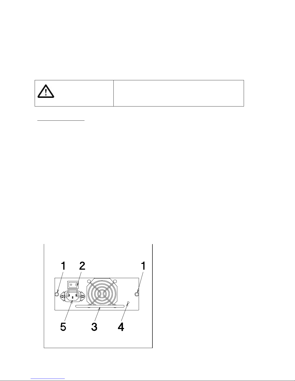
Advanced Technology and Systems Co., Ltd.
60
5.2 Power Supply Module Failure
The “PWR SUPPLY FAIL” message will be displayed on the display panel if one of the dual power
supply failed and the power supply’s status indicator has turned off. This indicates a power supply
module failure. Replace the power supply module by following the procedure indicated below.
WARNING
Replace the power supply module while power off. Do not put
your hands into the removed area of the power supply.
Replacement Procedure
1. Switch off the power switch on the front panel.
2. Set the power switch to “0” of the power supply module located on the rear side.
3. Disconnect all the cables (Power cable X 2, SCSI cable and etc.)
4. Unscrew the failed power supply module.
5. Pull out the failed power supply module.
6. Install the replacement power supply module.
7. Screw the fix screws (2X) of the power supply.
8. Reconnect all the cables that were disconnected in procedure no.3.
9. Set the power switch to “1” of the power supply module located on the rear side.
10. Switch on the power switch on the front panel.
11. Make sure that the “PWR SUPPLY FAIL” is not displayed anymore. Contact your sales
representative for repair if “PWR SUPPLY FAIL” message is still displayed after the power
supply module has been replaced.
1. Power supply module screws
2. Power supply switch
3. Power supply module handle.
4. Power supply status indicator
5. Connector for power cable.
Page 70
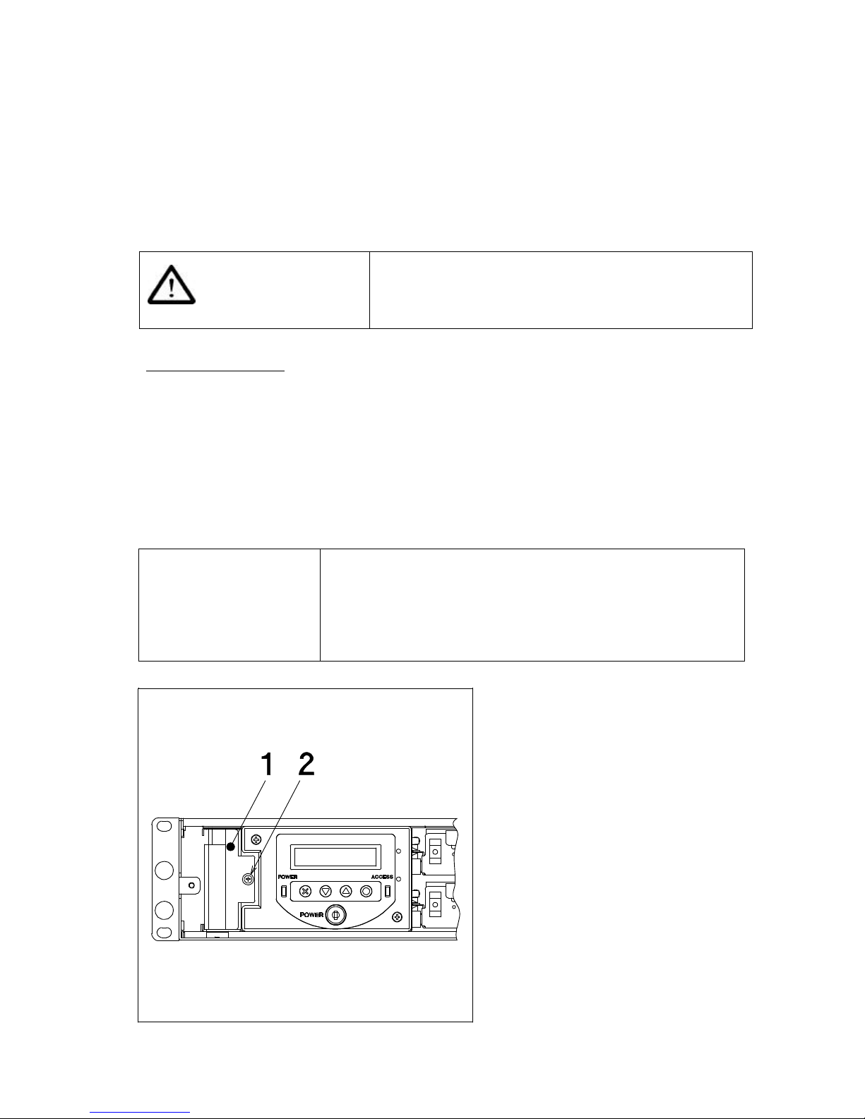
ArrayMasStor J Series User’s Manual
61
5.3 Fan Module Failure
The “FAN FAIL” message will be displayed on the display panel, if one of the fans failed in the fan
module. Replace the fan module immediately.
It is possible to replace the fan module while the subsystem is in operation, however, it should in a
short period of time since the cooling in the system is not enough.
WARNING
Do not enter the fingers into the removed area.
Replacement Procedure
1. Unscrew and remove the front cover. (See 2.1 Front side)
2. Unscrew the fan module. (refer below)
3. Pull out the fan module.
4. Install the replacement fan module.
5. Fasten the fan module using the fix screws.
6. Install the front cover.
IMPORTANT !
• The “FAN FAIL “ indication will be erased within one (1)
minute. Call your sales representative for repair if “FAN FAIL”
is still displayed after one (1) minute.
• The “P/S and FAN FAIL” indication will be displayed if both
power supply and fan modules have failed.
Without front cover
1. Fan module
2. Fan module fix screw
Page 71

Advanced Technology and Systems Co., Ltd.
62
5.4 Other Failures
If replacing new drive unit, fan module or power supply module doesn’t solve any troubles, contact
your sales representative.
Page 72
ArrayMasStor J Series User’s Manual
63
Appendix A Specifications
AXRR-J182S(-T) AXRR-J183S(-T) AXRR-J184S(-T)
RAID 0 capacity
36GB 54GB 72.1GB
RAID 1 capacity
17.9GB 26.9GB 36GB
RAID 5 capacity
N/A 36GB 54GB
RAID level
0,1
1
0,1,5
2
0,1,5
Host interface
SCSI-3(Single Ended/LVD)
Max. transfer rate
40MB/s
Cache buffer
64MB
Max. number of drives
2 3 4
HDD Capacity
18GB 18GB 18GB
AXRR-J462S(-T) AXRR-J463S(-T) AXRR-J464S(-T)
RAID 0 capacity
92GB 138GB 184GB
RAID 1 capacity
46GB 69GB 92GB
RAID 5 capacity
N/A 92GB 138GB
RAID level
0,1
1
0,1,5
2
0,1,5
Host interface
SCSI-3(Single Ended/LVD)
Max. transfer rate
40MB/s
Cache buffer
64MB
Max. number of drives
2 3 4
HDD Capacity
46GB 46GB 46GB
AXRR-J762S(-T) AXRR-J763S(-T) AXRR-J764S(-T)
RAID 0 capacity
153GB 230GB 307GB
RAID 1 capacity
76.8GB 115GB 153GB
RAID 5 capacity
N/A 153GB 230GB
RAID level
0,1
1
0,1,5
2
0,1,5
Host interface
SCSI-3(Single Ended/LVD)
Max. transfer rate
40MB/s
Cache buffer
64MB
Max. number of drives
2 3 4
HDD Capacity
76.8GB 76.8GB 76.8GB
*1 RAID Level 5 can be configured if drive unit is added.
*2 RAID Level 0 and 1 , if set as spare drive.
Page 73
Advanced Technology and Systems Co., Ltd.
64
All Models
Size (WxHxD)
483 x 88 x 509 mm (Rack model)
200 x 489 x 509 mm (Tower model)
Weight
18.5 kg (4 hard disks included)
Environment
Temperature : 5 – 40oC / Humidity : 10-90% (non-condense)
Power
100 ~ 240 V AC (50/60Hz)
Current
1.0 A (100V)
Capacity refers to the approximate storage capacity when used in RAID levels 0,1 and 5, without a
spare drive.
The actual capacity depends on the operating system, the number of drives and the configuration.
The specifications or physical appearance of the ArrayMasStor may change without prior notice.
Page 74

ArrayMasStor J Series User’s Manual
65
Appendix B Accessories
Accessories for the ArrayMasStor (AXRR-JxxxS-(T).
• Support Angle for installation to cabinet ( with M6 screws and floating knot ) 1 set
* shipped only with Rack model ( not included with AXRR-JxxxS-T model )
* may not fit on some of the EIA 19” cabinet
• SCSI Terminator (Part No.: A208243 ) x 1
• Power Cable ( Part No.: A208079 ) x 2
• Drive Lock Key ( Part No.: A200213 ) x 2
• Power On/Off Key ( Part No.: A207183 ) x 2
• ArrayMasStor J series User’s Manual ( this booklet ) ( Part No.: A208233 ) x 1
Page 75

Advanced Technology and Systems Co., Ltd.
66
Appendix C Default Configuration
The ArrayMasStor’s default configuration is as follows.
DEFAULT VALUE
SCSI ID 0
Number of LUN 1
RAID level More than 3Drive Model: 5
2Drive Model: 1
Hot spare drive No
Buzzer mode On
Auto reconstruction mode On
Cache buffer mode On
AIX Off
UNIX C/H/S Off
Ultra SCSI On
Initiator mode Off
Background surface verify On
Period of surface verify Weekly
Start time Sunday at 00:00
Execution time 60 minutes
DPO/FUA bit OFF
Password 1 2 3 4
Page 76
ArrayMasStor J Series User’s Manual
67
Appendix D Replacement Parts
The following items are defined as field replaceable parts.
Parts Name Parts Number Description
18GB drive unit A208084 Replacement/addition for AXRR-J18*S/drives
46GB drive unit A208218 Replacement/addition for AXRR-J46*S/drives
76GB drive unit A208263 Replacement/addition for AXRR-J76*S/drives
Replacement Box for
AXRR-JxxxS
A208244
Replacement for AXRR-JxxxS (except drive units
and RAID controller card)
Replacement Box for
AXRR-JxxxS-T
A208245
Replacement for AXRR-JxxxS-T (except drive units
and RAID controller card)
Replacement RAID
controller card
A208246
Support angle for
installation to cabinet
A208224 Shipped with rackmount type machine only
Replacement power supply
module
A207620
Replacement fan module A208248
Power Cable A208079
Terminator A208243
Drive lock/key A200213 Replacement for all J Series
Power On/Off key A207183
Page 77
Advanced Technology and Systems Co., Ltd.
68
Appendix E Feature Setting
Setting ArrayMasStor’s features depends on the number of drives configured. Refer the chart when
changing the ArrayMasStor configuration.
No. of Drives
Feature
RAID Level Spare
1 2 3 4
5 Assigned
X X X O
5 Not assigned
X X O O
1 Assigned
X X O O
1 Not assigned
X O O O
0 Assigned
X X X X
0 Not assigned
X O O O
Where:
O – means configuration is ALLOWED.
X – means configuration is NOT ALLWED.
Page 78

ArrayMasStor J Series User’s Manual
69
Electronic Emission Notices
Federal Communications Commission (FCC) Statement
Note: This equipment has been tested and found to comply with the limits for a Class B digital device,
pursuant to part 15 of the FCC Rules. These limits are designed to provide reasonable protection
against harmful interference in a residential installation.
This equipment generates, uses and can radiate radio frequency energy and, if not installed and used in
accordance with the instructions, may cause harmful interference to radio communications.
However, there is no guarantee that interference will not occur in a particular installation. If this
equipment does cause harmful interference to radio or television reception, which can be determined
by turning the equipment off and on, the user is encouraged to try to correct the interference by one or
more of the following measures:
- Reorient or relocate the receiving antenna
- Increase the separation between the equipment and receiver.
- Connect the equipment into an outlet on a circuit different from that to which
the receiver is connected.
- Consult the dealer or an experienced radio/TV technician for help.
FCC WARNING
Properly shielded and grounded cables and connectors must be used in order to meet FCC emission
limits. Proper cables and connectors are available from ADTX authorized dealers or contributor.
ADTX is not responsible for any radio or television interference caused by using other than
recommended cables and connectors or by unauthorized changes or modifications to this equipment.
Unauthorized changes or modifications could void the user’s authority to operate the equipment.
Page 79
 Loading...