

Page 1
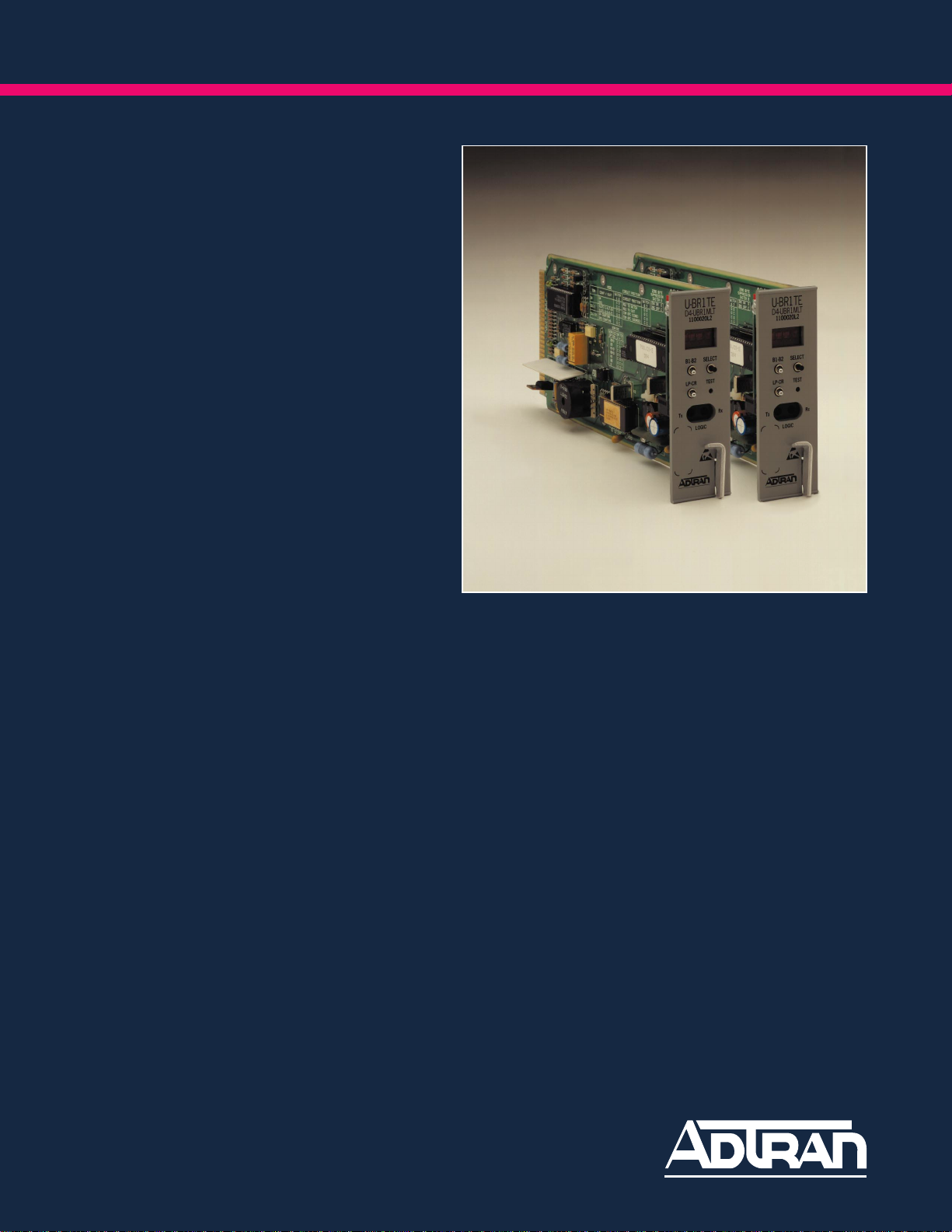
U-BR1TE
ISDN 2B1Q INTERFACE
Page 2

FEATURES
U-BR1TE
• Conforms to ANSI T1.601-1992
• Plugs into WECO D4 Channel Bank, ADTRAN
BR1/8 BR1TE bank, and ACT 1241
• Designed for use in SLC-96 terminals
• Basic Rate 2B+D service
• Faceplate Bantam jacks for maintenance testing
BENEFITS
• Extends range of 2-wire U-interface using T carrier
• Suitable for both Central Office and customer
premises environments
DESCRIPTION
• TR-NWT-000397 3 DS0 format and T1 facility
performance monitoring
• Loopback features available on faceplate
• 18,000 ft. nominal range, mixed gauge
• U-BR1TE/MLT supports Mechanized Loop Testing
• Use of D4 bank adds flexibility and extends life of D4
equipment
The ADTRAN U-BR1TE is a device which enables
transport of ISDN Basic Rate (2B+D) information over T
carrier lines. This is accomplished by the insertion of the two
"B" channels at 64 kbps and a single "D" channel at 16 kbps
into 3 DS0 time slots. The U-BR1TE provides a standard
U-interface which operates at 160 kbps full duplex over a
single twisted pair of wires. The U-BR1TE may be used at
both the Central Office Terminal location (COT) and the
Remote Terminal location (RT). Clear Channel capabilities
(B8ZS) are not required of the T1 facility if Zero Byte
Suppression is enabled. The U-interface available at the
U-BR1TE conforms to ANSI standards and performs all
Layer 1 functions.
The U-BR1TE plugs into a single D4 channel slot. It
occupies the time slot in which it is inserted, and the next two
adjacent time slots when delivering 2B+D service. The
U-BR1TE meets the ones density requirement of the T
carrier through the use of zero byte substitution and
associated flags in the “D” channel DS0 slot according to
TR-NWT-000397.
Maintenance and testability is provided for on the
U-BR1TE's front panel. A four-character display provides
an indication of Loop Activation, Out-of-Service, and Test.
The Select button is used with the four-character display to
determine which network element is to be looped back. The
B1-B2 switch determines which channel is to be looped
back. The LP-CR switch determines the direction of the
loopback. The Test button, which activates the unit's test
features, is recessed to prevent any inadvertent operation.
The U-BR1TE/MLT contains the same capabilities as
the U-BR1TE, with the addition of compatibility with
Mechanized Loop Testing (MLT 3.0/ISDN) according to TRNWT-000397, Issue 3, June 1992. When configured and
installed in a SLC-96 channel bank, the U-BR1TE/MLT
allows testing the local loop cable drop using an Extended
Pair Gain Tester (XPGTC).
Page 3
ISDN BR1/8 Bank (BR1/8)
The ADTRAN BR1/8 BR1TE bank provides an alternative
means of housing the ADTRAN U-BR1TE or T-BR1TE and
provides network termination for a T1 line. The BR1/8 contains
eight channel slots to accommodate up to eight U-BR1TEs or
T-BR1TEs. Each channel slot contains three DS0 timeslots
allowing all of the channel slots to be used when delivering
ISDN Basic Rate (2B+D) Service. The BR1/8 is an economical
means to offer ISDN Basic Rate via T carrier. Mounting slots
are provided for eight common equipment cards: a PAU, PCU,
OIU-2, RU, LIU, ACU, TU, and CAU. It is available in 23-inch
mounting.
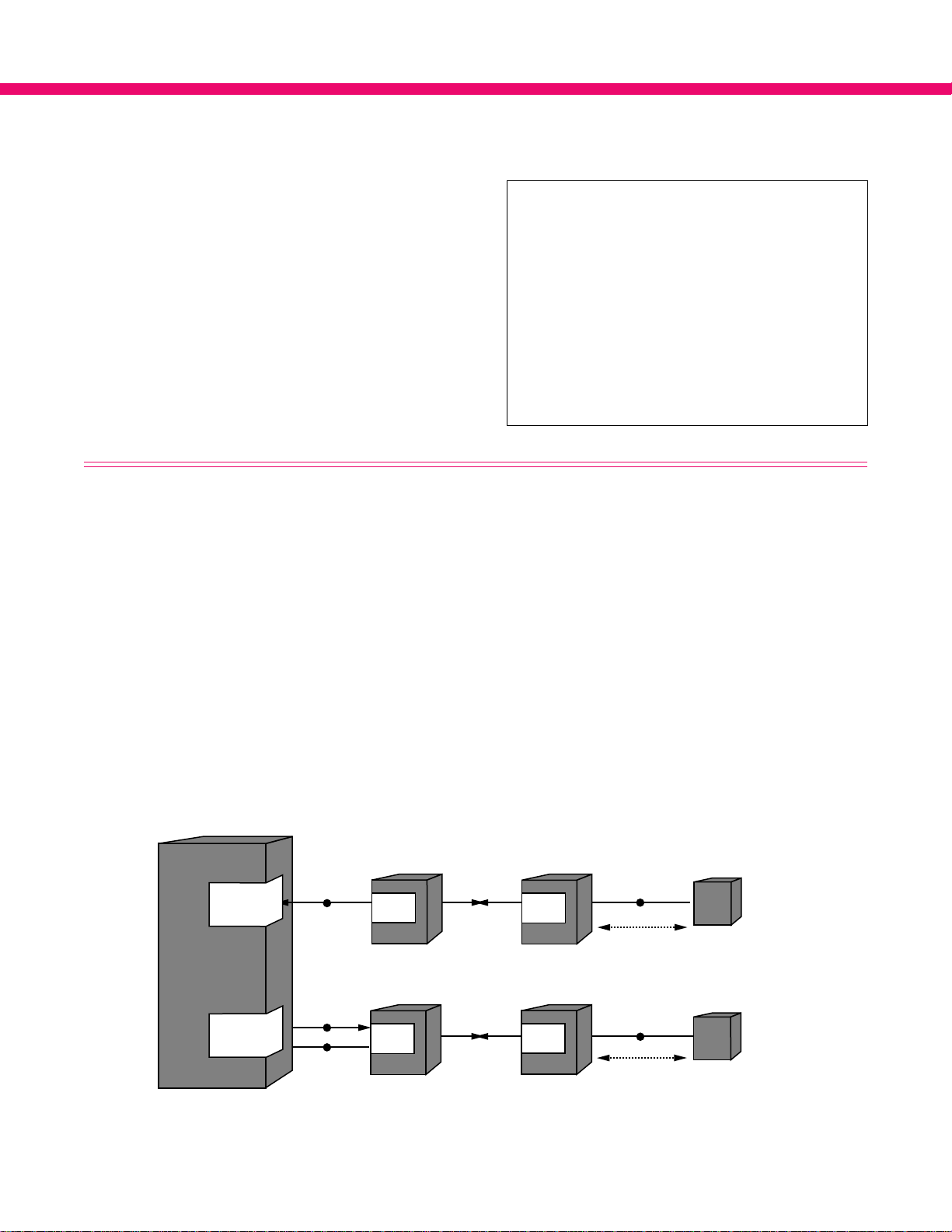
APPLICATIONS
The ADTRAN U-BR1TE is suitable for use in both
Central Office and customer premises environments. The
use of a single wire pair for full-duplex operations greatly
simplifies the administration of cable plant. The capability
of the U-interface to serve mixed wire gauges, and nominal
distances up to 18,000 ft. make it the universal choice for
ISDN deployment.
The ADTRAN U-BR1TE is ideally suited when the
need arises to extend ISDN service beyond the normal
U-BR1TE Applications
S
D
N
S
W
T
C
H
I
U
U
LT
I
T
NT
T
D4 (BR 1/8)
U-BR1TE
CHANNEL
BANK
D4 (BR 1/8)
U-BR1TE
CHANNEL
BANK
servicing range. The ability to provide ISDN services
is only limited by the range of available T carrier lines.
In instances where the 2B1Q U-interface card is
not available in the digital switch, it is possible to use
ADTRAN T-BR1TEs and U-BR1TEs in a mixed
application. This application allows the 2B1Q T1.6011992 U-interface to be delivered from a digital switch
which does not yet support it.
LOCAL EXCHANGE
D4 (BR 1/8)
U-BR1TE
CHANNEL
BANK
LOCAL EXCHANGE
D4 (BR 1/8)
U-BR1TE
CHANNEL
BANK
U
NT1
18,000 FT.
U
NT1
18,000 FT.
Page 4

U-BR1TE SPECIFICATIONS
Loop Interface:
Line: 2-Wire (TIP and Ring)
Operating Mode: Full-duplex
Data Rate: 160 kbps total; 144 kbps available to customer
Signal Format: 2B1Q
Output Amplitude: 2.5 Volt, Zero-to-Peak
Tx Source Impedance: As per ANSI T1.601-1992
Rx Source Impedance: As per ANSI T1.601-1992
Receiver Sensitivity: As per ANSI T1.601-1992
DS1 Facility Interface: Fully compatible with WECO D4 Channel Bank Equipment
Network Compatibility: ISDN and other digital service, according to TR-NWT-000397
Faceplate Controls and Indicators:
Controls: B1/B2 Bearer channel Select switch
LP/CR Loop or carrier direction Select switch
Select Scrolls through valid loopback addresses on four-character display
Test Activates selected loopback
Indicators: Four-character display is used to select loopback address and display loopback status.
Test: Bantam test jacks for TPI 108/109 RT II or equivalent test sets
Display Interpretation
ACTV IN PROG Activation in progress, the 2-wire loop is attempting to activate.
LOOP lS DOWN The 2-wire loop is not activated.
ADR# LOOP BACK A distant unit with address # is in a loopback commanded from this card.
NT1 LOOP BACK The NT1 is in loopback as commanded from this card.
B1 LOOP BACK This card is currently looping back channel B1 as commanded from a far unit.
B2 LOOP BACK This card is currently looping back channel B2 as commanded from a far unit.
2B+D LOOP BACK This card is currently looping back all channels as commanded from a far unit.
BANK CR FAIL Bank carrier fail, the channel bank is not receiving data from the T carrier.
XMIT CR SIDE Transmit carrier side, forcing the injection of 64 kbps data into a Bearer channel from the front panel Bantam jack into the carrier direction.
XMIT LP SIDE Transmit loop side, forcing the injection of 64 kbps data into a Bearer channel from the front panel Bantam jack into the loop direction.
MADE B1 LPBK Made B1 loopback, manually forced the Bearer channel B1 loopback in both the network and customer directions.
MADE B2 LPBK Made B2 loopback, manually forced the Bearer channel B2 loopback in both the network and customer directions.
CHCK TEST SET Check test set, ensure test set Tx probe is properly inserted into faceplate Bantam jack and configured as NEAR LOGIC.
FAR END OPEN The unit on the far end of the carrier is not present or not configured properly.
Mechanical:
Size: 4.4" H x 10" D x 1.4" W
Weight: 10 oz.
Mounting: Mounts in WECO D4 Channel Bank/SLC-96 terminals
Power: Current Drain On-Card Dissipation
-48 V: 40mA (in LUNT mode) 1.95 W maximum
5V: 5mA Display OFF (normal operating mode)
45mA Display ON
ORDERING INFORMATION: The part numbers for the U-BR1TE are provided below.
Equipment Part Number
U-BR1TE 1100020L1
U-BR1TE MLT 1100020L2
BR1/8 BR1TE BANK 1150018L1
901 Explorer Boulevard • Huntsville, Alabama • 35806-2807 • (205) 971-8000 • FAX (205) 971-8699
61100.020L1-8C
August 1993
Specifications subject to change without notice.
Printed in U.S.A.
 Loading...